Belmed PC7-C User manual
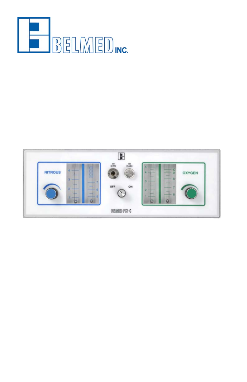
PC7-C Flowmeter O2/N2O Sedation Unit
Instruction Manual

!
IMPORTANT:
READ MANUAL COMPLETELY BEFORE OPERATING THIS DEVICE
This manual contains instructions on periodically required checks to be performed
by the user. These checks are necessary to ensure the proper performance of this
device and its safety features.
RETAIN THIS MANUAL FOR FUTURE REFERENCE
CAUTION: Federal law requires this device for use by or on the order of a physician
or dentist.
CAUTION: Do not attempt to repair, alter, or calibrate this device. Unauthorized
repair, alteration or misuse of this device is likely to adversely affect the
performance and will void the warranty.
WARNING: The PC7-C and its accessories, in need of repair, should ONLY be
repaired by Belmed, Inc. or an authorized Belmed, Inc. dealer.
WARNING: The PC7-C and its accessories are designed to perform in accordance
with the product specications when installed, operated and maintained as
instructed in this manual.
The National Institute for Occupational Safety and Health has issued a warning
for dental workers exposed to N2O during administration of N2O/O2 conscious
sedation analgesia. NIOSH has recommended that exposures should be minimized.
Contact NIOSH to receive NIOSH Publications on Control of Nitrous Oxide in Dental
Operatories at 1-800-232-4036. Exposure can be minimized by effective controls,
including System Maintenance, Ventilation, and Work Practices can effectively
reduce N2O concentrations in dental operations. A scavenger system is a
signicant part of exposure control.
Your sedation machine includes a fail-safe and other safety features. It also
includes the required and accepted specications by the ADA Council on Dental
Materials and Devices. Which includes Emergency Air Valve, Rebreathing Check
Valve, and Resuscitator Quick Connect. The ADA also requires the system be
installed by a competent supplier of gases and equipment. The gas storage and
delivery system should meet the recommendations for the National Fire Protection
Association (See NFPA Code).
WARNING
1

Cut-Out Dimensions for PC7-C............................................................12
Installation...............................................................................................6
PC7-C Flowmeter Dimensions..............................................................11
PC7-C Flushmount Flowmeter................................................................3
PercentageChart..................................................................................14
Purchase Record...................................................................................13
Remote Tee Block Hose Barb Option....................................................8
Remote Tee Block Template................................................................12
Remote Tee Bracket Installation......................................................9-10
Scavenger Rubber Goods Assembly....................................................7
TeeInstallation.........................................................................................8
Test Procedures/Operation....................................................................4
Warnings...................................................................................................1
Warranty.................................................................................................13
Index
2
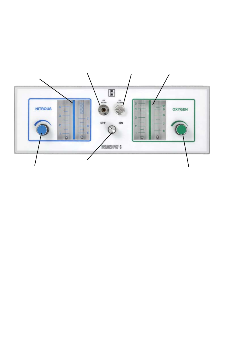
PC7-C Flushmount Flowmeter
The PC7-C has been recongured to t ush into today’s
cabinetry and provides the same time proven precision
and dependability as our stand PC-7 unit.
Nitrous Oxide
Flowmeter Tubes
Oxygen Resuscitator
Quick Connect O2 Flush
Oxygen
Flowmeter Tubes
Oxygen Flow
Control
On/Off Control
Nitrous Oxide
Flow Control
gure 1
Dimensions
4.25” H x 12.187” W x 4.687” D
On/Off Control simple 1/4 turn,
establishes a 3 liter minimum O2
ow.
O2 Flush provides a rapid ow
of oxygen directly into patient
breathing circuit.
Flow Control Valves Micrometer
needle valves allow quick
responsive ow adjustments.
Needle valve design prevents seat
damage.
Dual Cascading Flowmeter Tubes
are calibrated in liters per minute at
½ liter increments.
Oxygen Fail-Safe Automatically
and proportionally reduces N2O in
the event O2 is reduced or shut off.
Non-Rebreathing Check Valve
Prevents the rebreathing of expired
gases and guards against CO2
build-up.
Air Intake Valve entrains ambient air
into the breathing circuit in the event
ow from the machine is lost for any
reason.
Solid Gas Control Block Designed to
eliminate internal gas leaks
Oxygen Resuscitator Quick Connect
provides connection of auxiliary
resuscitation equipment.
3

Test Procedures
Note: Failure of the following test will require unit to be returned for service.
These tests must be conducted periodically to ensure proper operation.
(Refer to gure 1)
Test: Connect unit to a 50psi gas source. Check to make sure control
valves are turned off. Gently turn both valves clockwise until unit
resistance is felt.
1. Minimum oxygen: Turn on unit by pushing and turning on/off knob. A 3
liter ow of oxygen should be produced through O2 tube.
2. Oxygen ush: Depress O2 ush button to determine a rapid ow of
oxygen into breathing circuit. Flow should stop when button is released.
3. Maximum nitrous: Turn N2O needle valve wide open. N2O ow should
not exceed 7 LPM.
4. Fail safe test: Establish a 7 LPM N2O ow and 3 LPM O2 ow. Disconnect
O2 supply source or turn off O2 shut-off valve. Both O2 and N2O ows
should stop owing.
5. Air intake valve: Attach breathing bag and corrugated breathing tube
to proper ports of tee. Unit should be turned off and bag attened. Inhale
through breathing tube. Room air must enter through air intake located on
bottom of breathing circuit tee.
6. Non-Rebreathing valve: Connect corrugated tube to front of tee and
attempt to exhale through tube. Valve should be closed preventing
exhaled air from going into tube.
Maintenance
1. Ascertain a proper gas supply
pressure of 50psi.
2. Inspect machine hoses and
connections for damage, wear and
leaks daily.
3. Perform functional test periodically.
4. Keep unit clean. Unit and
accessories may be cleaned with
activated dialdehyde (Cidex).
Follow manufacturers directions
for use.
Service: All Service and repair must
be completed at Belmed, Inc. Have
your dealer return the unit to our
facility for service.
Operation
1. Turn unit on (100% O2) and set
the oxygen ow rate to equal total
gas ow (minute volume) to be
administered to patient. Maintain
breathing bag about ⅔full.
2. Apply nasal hood to patient.
3. Gradually introduce nitrous
oxide ow rate while proportionally
decreasing oxygen ow rate
(maintaining total gas ow) until
determined patient ratio is reached.
4. If oxygen is required, press oxygen
ush button.
5. To remove patient from conscious
sedation, return to 100% oxygen ow
rate established at beginning of
procedure. 4

IMPORTANT: PRIOR TO INSTALLATION, TURN OFF CENTRAL GAS SUPPLY SYSTEM AND
CLOSE ALL GAS TANK VALVES IN TANK ROOM. DISS SHUT-OFF VALVES SHOULD BE IN
CLOSED POSITION THROUGHOUT INSTALLATION OF THE FLOWMETER.
Install the gas lines: A qualied plumber can install the delivery piping up to and including the
DISS shut-off valves.
The dental dealer is responsible for the nal connections to the owmeter, the details of
owmeter installation checking for crossed-lines, leak testing of connections to the owmeter,
and basic owmeter operation.
1. Determine desired location of the owmeter. Use the provided cut-out dimensions to cut
an opening in the cabinet or mounting apparatus.
Note: Flowmeter location needs to accommodate 5 feet DISS hose-to-shut-off valve
distance, and 10 feet mixed gas hose-to-remote bag tee distance.
2. Determine the location of the remote bag tee that accommodates visual monitoring of
the breathing bag during patient treatment. Use the provided diagram to pre-drill and mount
the remote bag tee block. Insert tee and tighten set screw with provided Allen wrench.
(MAKE SURE SET SCREW IS ACCESSIBLE).
Note: Bag Tee ideally is to be installed within 10 feet of the owmeter.
3. Connect the O2 DISS hose (green) to the O2 shut-off valve and the N2O DISS hose (blue) to
the N2O shut-off valve.
4. Connect 10 feet mixed gas hose to the hose barb on the Remote Tee. Shorten the hose if
desired and attach the ferrules to the ends. Moisten the hose barb to ease installation.
5. Pull O2 and N2O DISS hoses and mixed gas hose through the cut-out for the owmeter and
attach O2, N2O and mixed gas hose to the back-side of the owmeter.
Note: Make certain hoses are not crimped. Check O2 and N2O hose
connections for leaks.
6. Position owmeter over opening and line up screws on the owmeter with the pre-drilled
holes of the cut-out. Secure the owmeter by tightening the provided nuts.
7. Perform the Check for Crossed Lines, The Leak Test of the Flowmeter Installation, and the
Flowmeter Function Test.
CHECK FOR CROSSED LINES: (Refer to NFPA Gas and Vacuum Systems for Type II Systems
Crossguard Warning.) Open both the O2 and N2O shut-off valves to allow gas to the
owmeter. Before using owmeter, check for crossed lines by opening the O2 valve and
making certain that only oxygen ows through the owmeter.
LEAK TEST OF THE FLOWMETER INSTALLATION: After all hose connections are tightened, turn the
ow control knobs to the off position and the on/off knob to the off position. Conrm that the
DISS shut-off valves are in the open position. Pressurize the sedation gas supply lines with 50psi.
Observe any pressure decay after an overnight time period. (5psi drop allowed.)
Installation
!Caution: Be sure to use two wrenches when
tightening or removing hoses from the gas ttings.
5
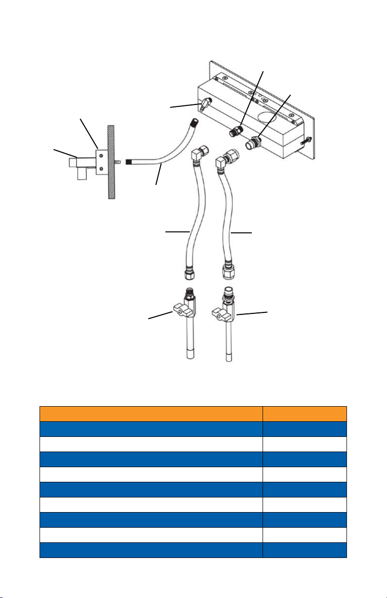
PC7-C Flushmount Flowmeter
Parts List
Description Part Number
Accessory Angle 5500-600
Flushmount Flowmeter (includes Remote Tee) 5500
Mixed Gas Hose (10ft) 5500-76
N2O DISS Hose (5ft) 8031
N2O DISS Shut-Off Valve 7302
O2 DISS Hose (5ft) 8030
O2 Diss Shut-Off Valve 7304
Remote Tee Block 5500-500
Sliding Bracket 5500-700
O2 DISS Male
N2O DISS Male
N2O DISS Hose
(green)
N2O DISS
Shut-off Valve
O2 DISS
Shut-off Valve
O2 DISS Hose
(blue)
Mixed Gas Hose
Bag Tee
Bag Tee Block
¼“ Hose Barb
gure 2
6

Scavenger Rubber Goods Assembly
Small Tube
7¼” – #25594
Scavenger
Hub – #22099
Large Tube
5” – #25593
Double Connector –
#21178
Small Y Connector –
#21246
Large Y Connector –
#21245
Spiral Vacuum
1½” – #25592
Spiral Vacuum
3½” – #25591
Vacuum Gauge –
#22122
Single Vacuum
Connector – #22122
↕
Tube Slide Double – #26253
Single Connector –
#21179
Double Tubing –
#25590
gure 3
gure 4
7

Remote Tee Block Hose Barb Option
Tee Installation
gure 5
gure 6
The hose barb can be moved from the back location to the down
location in a few simple steps.
1. Remove the hose barb with a 7/16” open end wrench.
2. Remove the plug with a 3/16” Allen wrench.
3. Wrap both the hose barb and plug with Teon Tape.
4. Tighten the hose barb to the bottom of the block.
5. Tighten the plug to the back of the block.
8

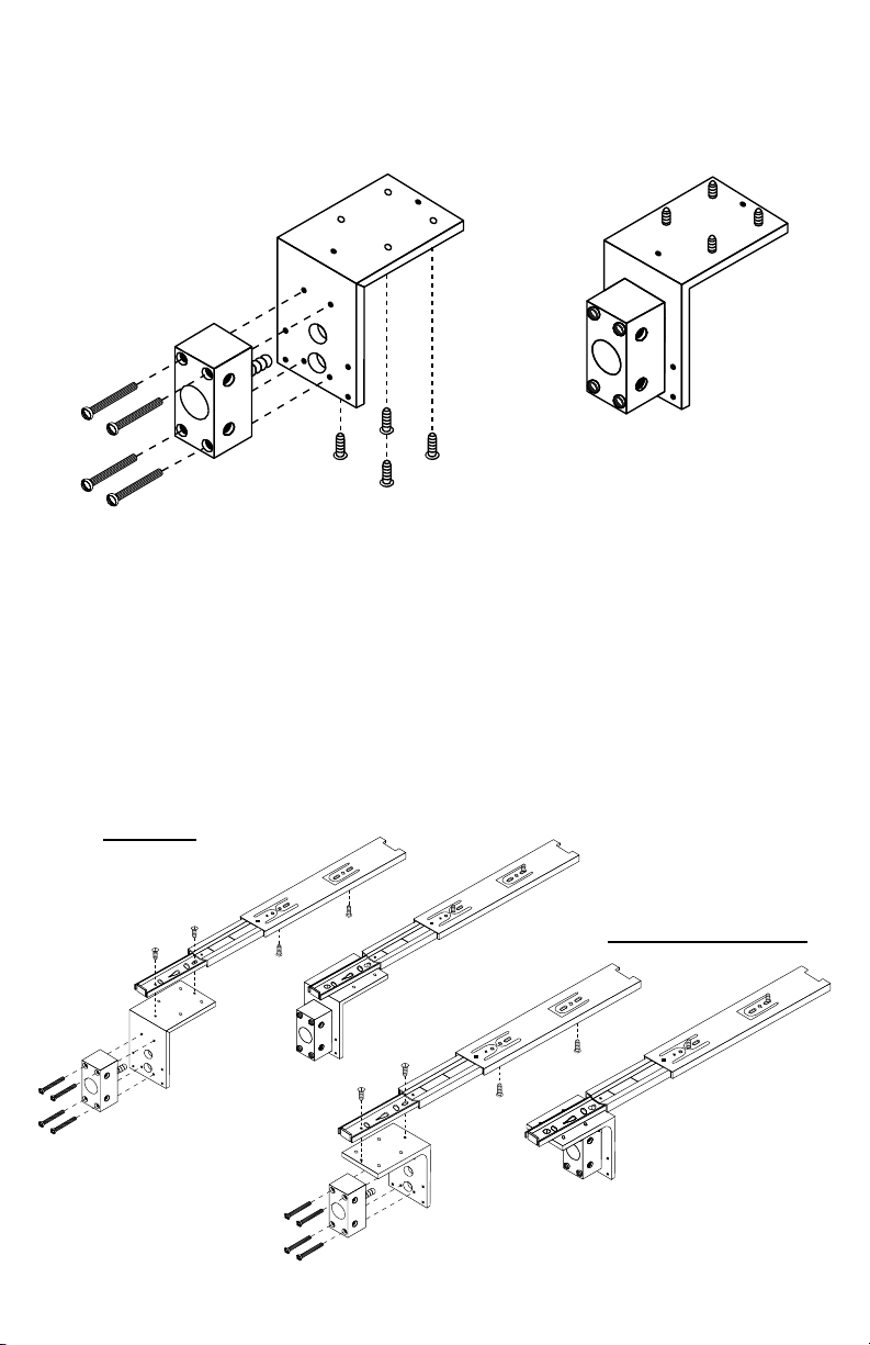
Remote Tee Bracket Installation
Left or Right Side Installation
gure 8
gure 7
gure 9
Compact (save 3”)
1. Use Remote Tee Bracket as drilling guide.
2. Pre-drill all 4 holes 7/64”
3. Mount Bracket with #8 x 5/8 wood screws (4 included).
4. Attach Remote Tee Block to the Remote Tee Bracket with #8 x 1 1/2”
machine screws (4 included).
5. Attach Mixed Gas hose to hose barb on block.
6. Insert Tee and tighten set screw with 3/32” Allen wrench.
7. Attach Rubber Goods.
Standard
9
Remote Tee Bracket Installation
Top Installation
1. Use Remote Tee Bracket as drilling guide.
2. Pre-drill all 4 holes 7/64”
3. Mount Bracket with #8 x 5/8 wood screws (4 included)
4. Attach Remote Tee Block to the Remote Tee Bracket with #8 x 1 1/2”
machine screws (4 included).
5. Attach Mixed Gas hose to hose barb on block.
6. Insert Tee and tighten set screw with 3/32” Allen wrench.
7. Attach Rubber Goods.
gure 10
gure 11
gure 12
Compact (save 3”)
Standard
10

PC7-C Flowmeter Dimensions
gure 13
gure 14
3.7250
12.1875
11.5900
9.6562
6.0937
3.8437
4.2500
2.1250
11
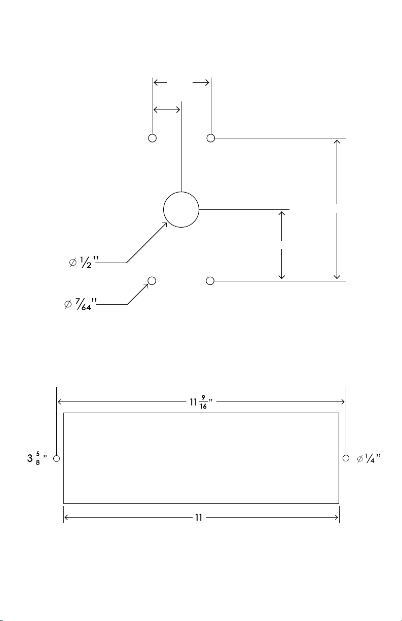
Remote Tee Block Template
Cut-Out Dimensions
”
0.834”
0.417”
2.0”
1.0”
(2X)
CUT–OUT DIMENSIONS
gure 15
gure 16
12

Purchase Record
MODEL NO. SERIAL NO. PURCHASE DATE
Denition of Warranty Return: A product or part covered by the Belmed, Inc. warranty, that
fails while the terms of the warranty are in effect.
THIS WARRANTY IS GIVEN IN PLACE OF ALL OTHER WARRANTIES, EXPRESSED OR IMPLIED, OF
MERCHANTABILITY, FITNESS FOR A PARTICULAR PURPOSE OR OTHERWISE.
No statement or claim about the product by any employee, agent, representative or dealer
of Belmed, Inc. shall constitute a warranty by Belmed, Inc. or give rise to any liability or
obligation of Belmed, Inc.
Subject to the next sentence, Belmed, Inc warrants that each product or part shall be
free from defects in workmanship and materials, under normal use and with appropriate
maintenance, for one (1) year from the date of delivery to customer. For plastic, rubber and
disposable parts or items Belmed, Inc. warrants only that each such part and item shall be
free from defects in workmanship and materials at the time of delivery to the customer.
Belmed, Inc.’s obligation for breach of this warranty, or for negligence or otherwise, shall
be strictly and exclusively limited to Belmed Inc.’s choice of repair or replacement of the
product or part. This warranty shall be void for any product on which the serial number has
been altered, defaced or removed.
Belmed, Inc. shall not be liable for any damage, injury or loss arising out of the use of
the product, whether as a result of a defect in the product or otherwise, if, prior to such
damagve, injury or loss, the product was (1) damaged, misused, or misapplied; (2) repaired,
altered or modied by persons other than Belmed, Inc. (3) not installed in strict compliance
with applicable codes and ordinances; or (4) not installed by Belmed, Inc. or an authorized
Belmed, Inc. dealer.
UNDER NO CIRCUMSTANCES SHALL BELMED, INC. BE LIABLE FOR INCIDENTAL OR
CONSEQUENTIAL DAMAGES AS THOSE TERMS ARE DEFINED IN THE UNIFORM COMMERCIAL
CODE.
Important: Traceability/Warranty Registration
Medical device legislation of 1976 mandates traceability of this
equipment. Please ll out and return warranty card.
Warranty
13

www.belmedinc.com
MEDICAL GAS SYSTEMS & EQUIPMENT
* Greater than 70% N2O administered exceeds the amount able to be delivered by sedation machine.
LPM OXYGEN
N
I
T
R
O
U
S
O
X
I
D
E
0.5 1 1.5 2 3 3.5 4 4.5 5 5.5 6 6.5 7 7.5 8 8.5 92.5 9.5 10
0.5 50% 33% 25% 20% 17% 14% 13% 11% 10% 9% 8% 8% 7% 7% 6% 6% 6% 5% 5% 5%
167% 50% 40% 33% 29% 25% 22% 20% 18% 17% 15% 14% 13% 13% 12% 11% 11% 10% 10% 9%
1.5 75% 60% 50% 43% 38% 33% 30% 27% 25% 23% 21% 20% 19% 18% 17% 16% 15% 14% 14% 13%
280% 67% 57% 50% 44% 40% 36% 33% 31% 29% 27% 25% 24% 22% 21% 20% 19% 18% 17% 17%
2.5 83% 71% 63% 56% 50% 45% 42% 38% 36% 33% 31% 29% 28% 26% 25% 24% 23% 22% 21% 20%
793% 88% 82% 78% 74% 70% 67% 64% 61% 58% 56% 54% 52% 50% 48% 47% 45% 44% 42% 41%
6.5 93% 87% 81% 76% 72% 68% 65% 62% 59% 57% 54% 52% 50% 48% 46% 45% 43% 42% 41% 39%
692% 86% 80% 75% 71% 67% 63% 60% 57% 55% 52% 50% 48% 46% 44% 43% 41% 40% 39% 38%
5.5 92% 85% 79% 73% 69% 65% 61% 58% 55% 52% 50% 48% 46% 44% 42% 41% 39% 38% 37% 35%
591% 83% 77% 71% 67% 63% 59% 56% 53% 50% 48% 45% 43% 42% 40% 38% 37% 36% 34% 33%
4.5 90% 82% 75% 69% 64% 60% 56% 53% 50% 47% 45% 43% 41% 39% 38% 36% 35% 33% 32% 31%
489% 80% 73% 67% 62% 57% 53% 50% 47% 44% 42% 40% 38% 36% 35% 33% 32% 31% 30% 29%
3.5 88% 78% 70% 64% 58% 54% 50% 47% 44% 41% 39% 37% 35% 33% 32% 30% 29% 28% 27% 26%
386% 75% 67% 60% 55% 50% 46% 43% 40% 38% 35% 33% 32% 30% 23%24%25%26%27%29%
14
Other Belmed Measuring Instrument manuals


