Belmed PC-7 User manual

PC-7 Flowmeter O2/N2O Sedation
Unit Instruction Manual

1
!
WARNING
IMPORTANT:
READ MANUAL COMPLETELY BEFORE OPERATING THIS DEVICE
This manual contains instructions on periodically required checks
to be performed by the user. These checks are necessary to
ensure the proper performance of this device and its safety
features.
RETAIN THIS MANUAL FOR FUTURE REFERENCE
CAUTION: Federal law requires this device for use by or on the
order of a physician or dentist.
CAUTION: Do not attempt to repair or alter this device.
Unauthorized repair, alteration or misuse of this device is likely to
adversely affect the performance and will void
the warranty.
CAUTION: Never oil or grease any part of this system.
The National Institute for Occupational Safety and Health has
issued a warning for dental workers exposed to N2O during
administration of N2O/O2 conscious sedation analgesia. NIOSH
has recommended that exposures should be minimized. Contact
NIOSH to receive NIOSH Publications on Control of Nitrous Oxide in
Dental Operatories at 1-800-232-4036. Exposure can be minimized
by effective controls, including System Maintenance, Ventilation,
and Work Practices can effectively reduce N2O concentrations
in dental operations. A scavenger system is a signicant part of
exposure control.
Your sedation machine includes a fail-safe and other safety
features. It also includes the required and accepted specications
by the ADA Council on dental materials and devices. Which
includes; emergency air valve, rebreathing check valve, and
resuscitator quick connect. The ADA also requires; the system to
be installed by a competent supplier of gases and equipment; the
gas storage and delivery system meets the recommendations for
the National Fire Protection Association. (See NFPA Code)

Arm Mounting........................................................................................11
Cabinet Bracket....................................................................................14
Cabinet Hinge Bracket Installation.....................................................13
Maintenance..........................................................................................5
Mobile Stand Detail...............................................................................16
Mobile Stand Installation........................................................................6
O2 Demand Valve................................................................................18
Operation................................................................................................5
PC-7 Flowmeter Description..................................................................3
PC-7 Flowmeter Dimension..................................................................15
PercentageChart..................................................................................22
Purchase Record...................................................................................21
Scavenger Rubber Goods Assembly..................................................10
Supply Hose Connections......................................................................9
Telescoping Arm System......................................................................12
Test Procedure.........................................................................................4
Wall Arm/Cabinet Bracket Installation.................................................8
Warnings...................................................................................................1
Warranty.................................................................................................20
Yoke.........................................................................................................7
Index
2

FLOWMETER HEAD DIMENSIONS
8.75”H X 3.75”W X 10.25”D
WEIGHT OF FLOWMETER HEAD
5lbs
BAG AND OUTLET DIAMETER
22mm (approx. ⅞”)
OXYGEN FLOW RANGE
3-10 LPM
NITROUS OXIDE FLOW RANGE
0-7 LPM
FAIL-SAFE TYPE
Proportional
PC-7 Flowmeter
Nitrous Oxide/Oxygen Flowmeter
Tubes are calibrated in liters per
minute at ½liter increments. A
minimum of 30% O2 is achieved by
limiting ows to a minimum of 3 liters
for O2 and a maximum of 7 liters
for N2O.
Flow Control Valves allows for quick
responsive ow adjustments.
Oxygen Fail-Safe automatically and
proportionally reduces N2O in the
event O2 is reduced or shut off.
Air Intake Valve entrains ambient air
into the breathing circuit in the event
ow from the machine is lost for any
reason.
Non-Rebreathing Check Valve
prevents the rebreathing of expired
gases and guards against CO2
build-up.
Oxygen Flush provides a rapid ow of
oxygen directly into patient breathing
circuit.
On/Off Control provides a 3 liter
minimum O2 ow when the unit is
turned on.
Oxygen Resuscitator Quick Connect
provides connection of auxiliary
resuscitation equipment.
Solid Block Design is designed to
eliminate internal gas leaks.
Nitrous Oxide
Flowmeter Tube
Flow Control
Oxygen Fail-Safe
Non-Rebreathing
Check Valve
Air Intake Valve
Oxygen
Flowmeter Tube
Solid Block
Design
gure 1
Oxygen Resuscitator
Quick Connect
Oxygen Flush
On/Off
3

Test Procedures
Note: Failure of the following test will require unit to be returned for service.
These tests must be conducted periodically to ensure proper operation.
(Refer to gure 1)
Test: Connect unit to a 50psi gas source. Check to make sure control
valves are turned off. Gently turn both valves clockwise until unit
resistance is felt.
1. Minimum oxygen: Turn on unit by pushing and turning on/off knob. A 3
liter ow of oxygen should be produced through O2 tube.
2. Oxygen ush: Depress O2 ush button to determine a rapid ow of
oxygen into breathing circuit. Flow should stop when button is released.
3. Maximum nitrous: Turn N2O needle valve wide open. N2O ow should
not exceed 7 LPM.
4. Fail safe test: Establish a 7 LPM N2O ow and 3 LPM O2 ow. Disconnect
O2 supply source or shut off O2 supply. Both O2 and N2O ows should
stop owing.
5. Air intake valve: Attach breathing bag and corrugated breathing tube
to proper ports of tee. Unit should be turned off and bag attened. Inhale
through breathing tube. Room air must enter through air intake located on
bottom of breathing circuit tee.
6. Non-Rebreathing valve: Connect corrugated tube to front of tee and
attempt to exhale through tube. Valve should be closed preventing
exhaled air from going into tube.
4

Operation
Maintenance
1. Ascertain a proper gas supply pressure of 50psi.
2. Inspect machine hoses and connections for damage, wear and
leaks daily.
3. Perform functional test periodically.
4. Keep unit clean. Unit and accessories may be cleaned with activated
dialdehyde (Cidex). Follow manufacturers directions for use.
Service: All Service and repair must be accomplished at Belmed, Inc.
Have your dealer return unit to our facility for service.
1. Turn unit on (100% O2) and set the oxygen ow rate to equal total gas
ow (minute volume) to be administered to patient. Maintain breathing
bag about ⅔full.
2. Apply nasal hood to patient.
3. Gradually introduce nitrous oxide ow rate while proportionally
decreasing oxygen ow rate (maintaining total gas ow) until determined
patient ratio is reached.
4. If oxygen is required, press oxygen ush button.
5. To remove patient from conscious sedation, return to 100% oxygen ow
rate established at beginning of procedure.
5

Installation Instructions
Flowmeter on Yoke Block Stand
Mobile stand assembly: Remove packaging from the base and column.
Push tapered end of column into base (gure 13).
Flowmeter attachment: Remove ½ in. diameter height adjustment rod
from column. Hand tighen the end of threaded rod into mounting adapter
located on bottom of owmeter. Lock rod into owmeter adapter by
tightening nut with ¾in. open end wrench while holding rod. Replace rod
into column and tighten toggle screw at desired height (gure 2).
Rubber goods: Connect breathing bag to bottom of bag tee. Connect
90 adapter to front of tee. Connect corrugated breathing tube to 90°
adapter. Connect nasal inhaler to other end of breathing tube (gure 6).
Connect gas supply hoses to DISS ttings located on bottom of owmeter
(gure 5).
Test machine.
Note: If optional O2 resuscitator is purchased with machine, plug hose end
into female quick connect located on bottom of machine. Depress button
to determine O2 ows through resuscitator. For demand ow test, breathe
through face mask (gure 15).
gure 2
Flowmeter Connection
to Mobile Stand
6

Yoke
Yoke block stand assembly: Remove packaging from the base, column,
and yoke block. Follow the assembly instructions in the yoke block
instruction manual to complete the assembly of these parts.
Flowmeter attachment: Remove ½ in. diameter height adjustment rod
from column. (Z bracket should already be attached to the height
adjustment rod). Use the two provided screws to fasten the Z bracket to
the Flowmeter. Replace rod into column and tighten height adjustment
knob at desired height (gure 3).
Rubber goods: Connect breathing bag to bottom of bag tee. Connect
90 adapter to front of tee. Connect corrugated breathing tube to 90°
adapter. Connect nasal inhaler to other end of breathing tube (gure 6).
Connect gas supply hoses to DISS ttings located on bottom of owmeter
(gure 5).
Test machine.
Note: If optional O2 resuscitator is purchased with machine, plug hose end
into female quick connect located on bottom of machine. Depress button
to determine O2 ows through resuscitator. For demand ow test, breathe
through face mask (gure 15).
gure 3
7
Installation Instructions
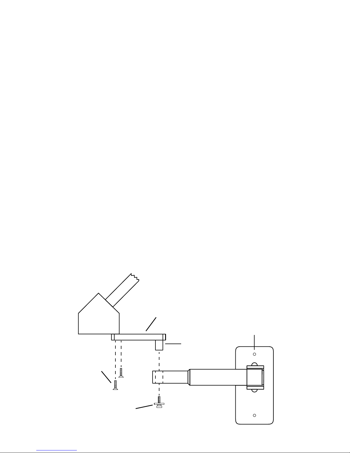
Flowmeter on Wall Arm or Cabinet Bracket
Arm Mounting Detail
Wall Arm/Cabinet Bracket: Attach arm to wall stud or other similar rm
support with lag screws (gure 7). Mount cabinet bracket to roof of
cabinet with lag screws (gure 9).
Flowmeter attachment: Remove screw and washer assembly from stud on
owmeter mount and attach owmeter to arm bracket by inserting stud
into hole located on arm. Replace screw and washer assembly into stud.
Telescoping arm will extend owmeter approximately a max of 24 in. from
mounting surface (gure 4).
Rubber goods: Connect breathing bag to bottom of bag tee. Connect
corrugated breathing tube to front end of tee. Connect nasal inhaler to
other end of breathing tube (gure 6).
Connect gas supply hoses to DISS ttings located on bottom of owmeter
(gure 5).
Test machine.
Note: If optional O2 resuscitator is purchased with machine, plug hose end
into female quick connect located on bottom of machine. Depress button
to determine O2 ows through resuscitator. For demand ow test, breathe
through face mask (gure 15).
gure 4
Telescoping Arm
⅝Mounting
Stud
#8-32
Retaining Screw
#10-24
Screws (2)
Arm Adapter
8
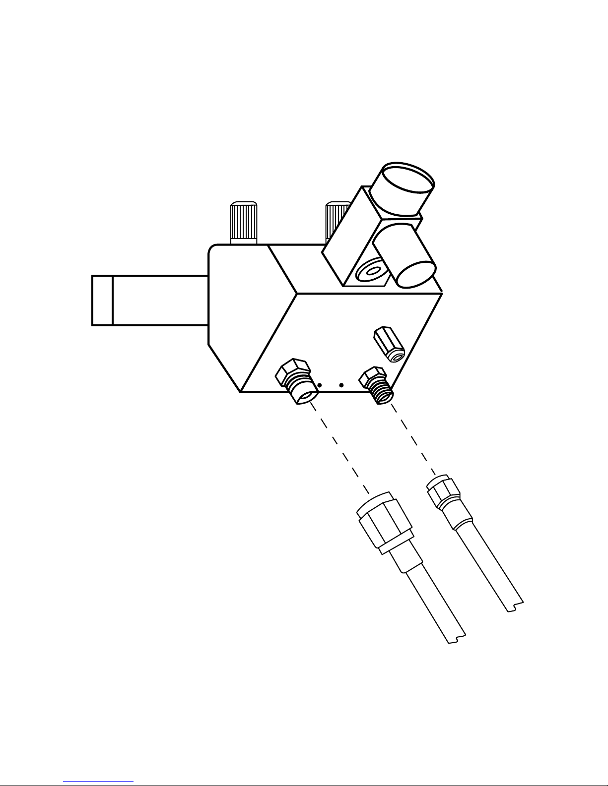
Supply Hose Connections
gure 5
N2O
(blue)
O2
(green)
9
Scavenger Rubber Goods Assembly
(Part #’s 5600-0001, 5600-0002, 5600-0003)
gure 6
3L Breathing Bag (not shown)
connects to bottom port
5600-0021
Connects to
vacuum supply
Scavenger inhaler
Pedo - 5600-0001
Medium - 5600-0002
Large 5600-0003
Scavenger inhaler
connects to open end
of breathing tube
Breathing Tube
connects to end port
5600-0022
90° Elbow (Optional)
5600-0015
10
Arm Mounting
heavy duty
expander ¼in. lag
screw
¼in. lag
screw
dry wall application
stud mounting method
(preferred)
stud
gure 7
11

Top View of Telescoping Arm System
gure 8
27 in.
24 in.
Extends controls up to approximately 24 in. from wall surface
12
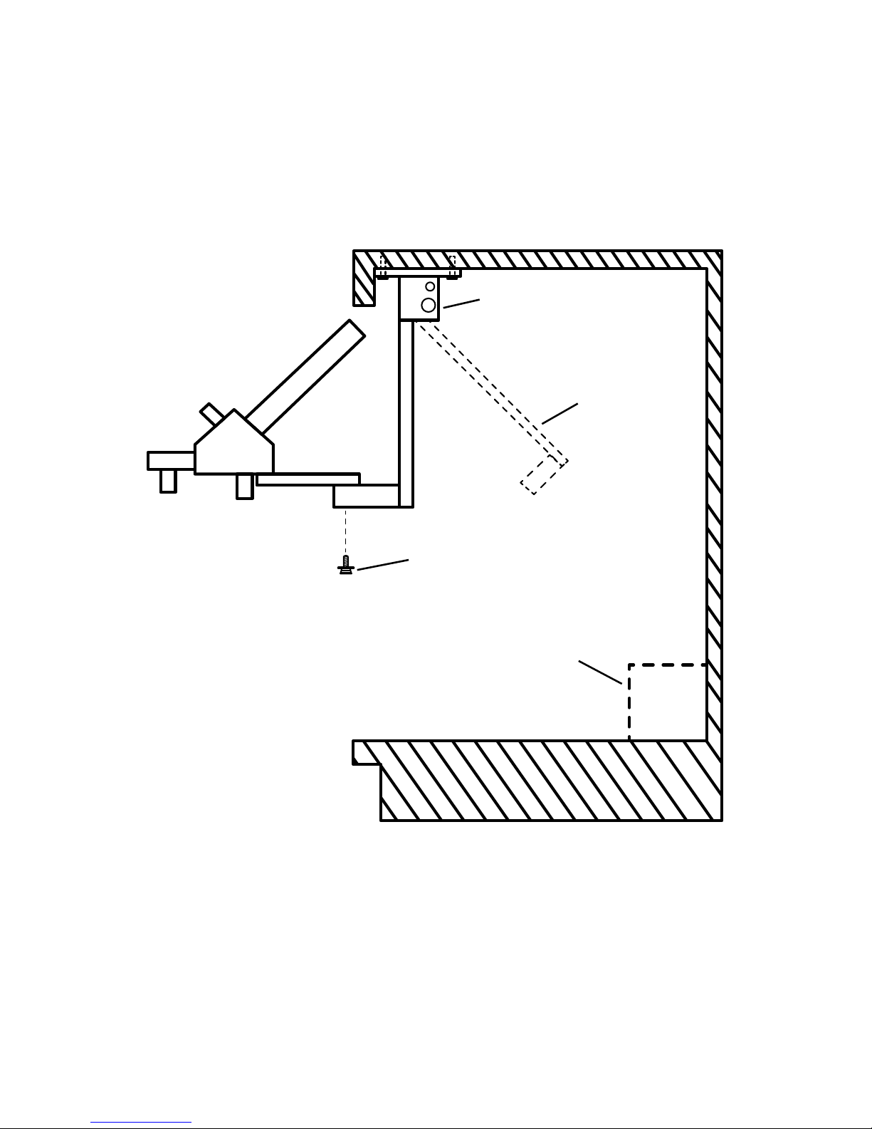
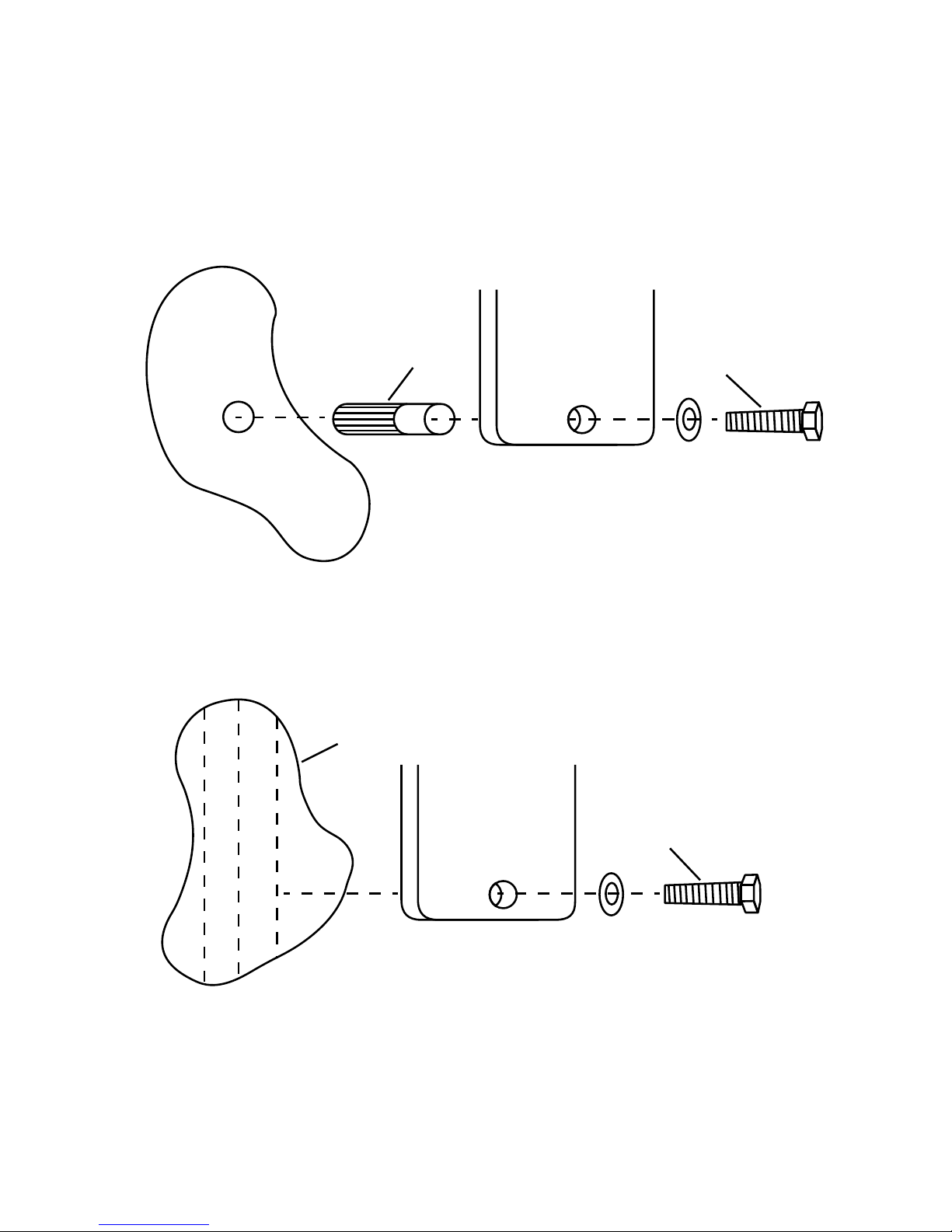
Cabinet Hinge Bracket InstallationCabinet Hinge Bracket Installation
Cabinet Bracket Detail
Mount bracket as shown to roof of cabinet with 4 lag screws up to ¼in.
diameter that is suitable for type of cabinet construction and ensures that
bracket will not loosen. Note: If the top material inside of cabinet is too thin
to secure bracket, it may be necessary to rst attach a piece of 1 in. x 6 in.
board to the cabinet and then attach cabinet bracket to board.
Operation: To release bracket for use from its retracted position, hold
owmeter with one hand and release catch (located on upper right of
bracket) by pulling knob to right. Allow owmeter to gently come forward
and release pull knob. Catch will release itself when the use position is
reached. To stow unit; pull knob to release catch, push unit back, and
release knob. Unit will latch itself when stowed position is reached.
catch rod – pull to release
retracted position
for storage
Free cabinet space required:
(inside dimensions)
H – 22 in.
D – 12 in.
W – 6 in.
8-32 retaining
screw
supply connections
(typical)
gure 9
13
Cabinet Bracket
10 ½in.
4 in.
mounting holes (4)
catch/release
gure 10
14

Flowmeter Head
Overall Dimensions
gure 11
3 ¾ in.
10 ¼ in.
8 ¾ in.
15

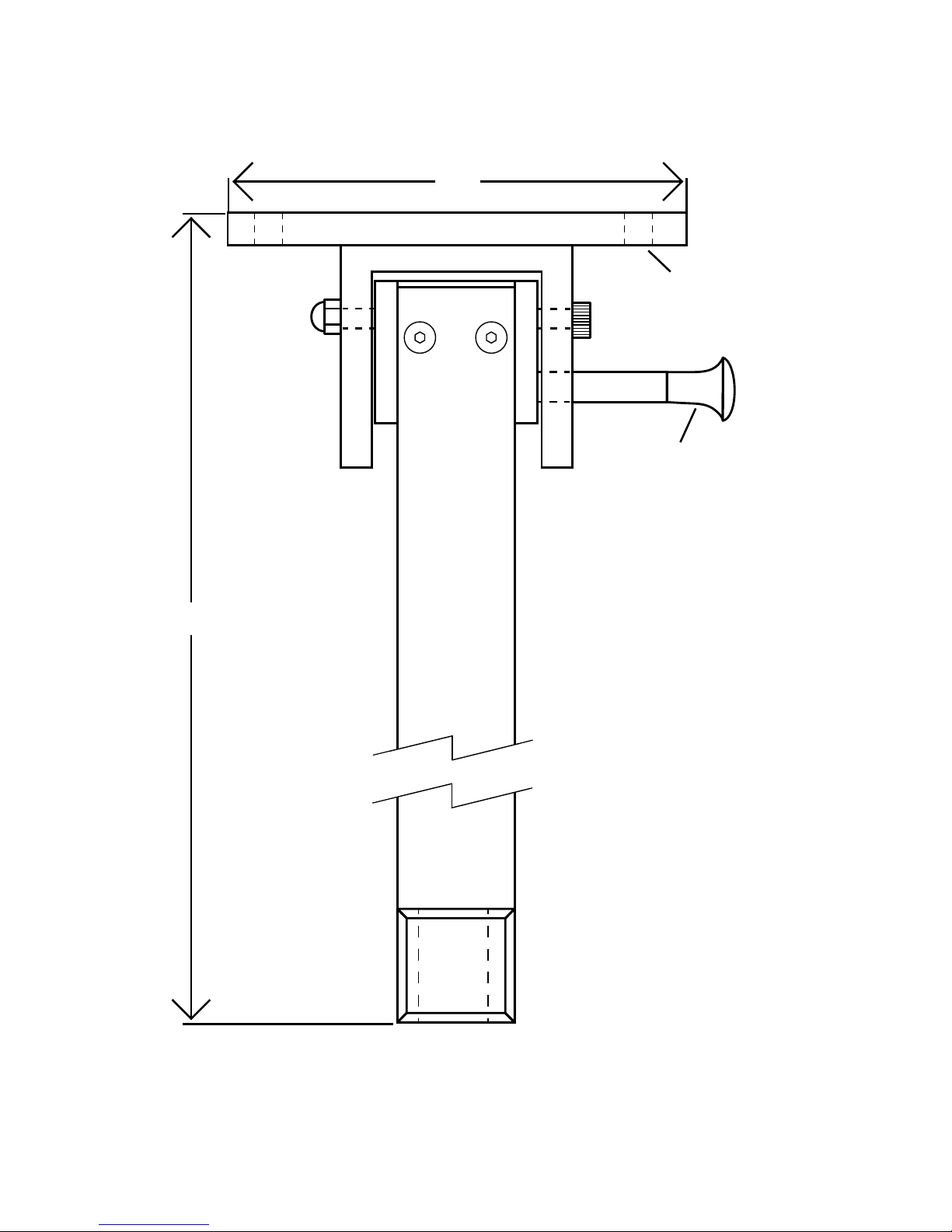
Mobile Stand Detail
SHORT STAND
5300-1001
HEIGHT
20.5 in.
WIDTH
19 in.
HEIGHT ADJUSTMENT
10 in.
TALL STAND
5300-1011
HEIGHT
30.5 in.
WIDTH
19 in.
HEIGHT ADJUSTMENT
10 in.
gure 12
gure 13
16

Yoke System
gure 14
HEIGHT
31 in.
WIDTH
19 in.
DEPTH
19 in.
17

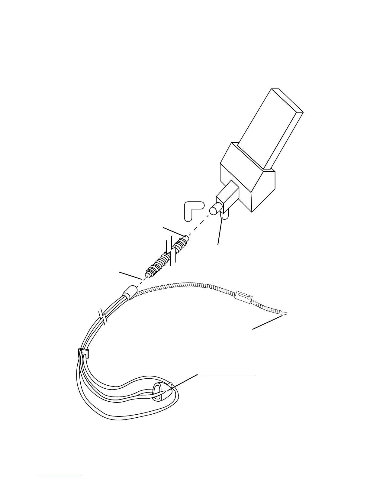
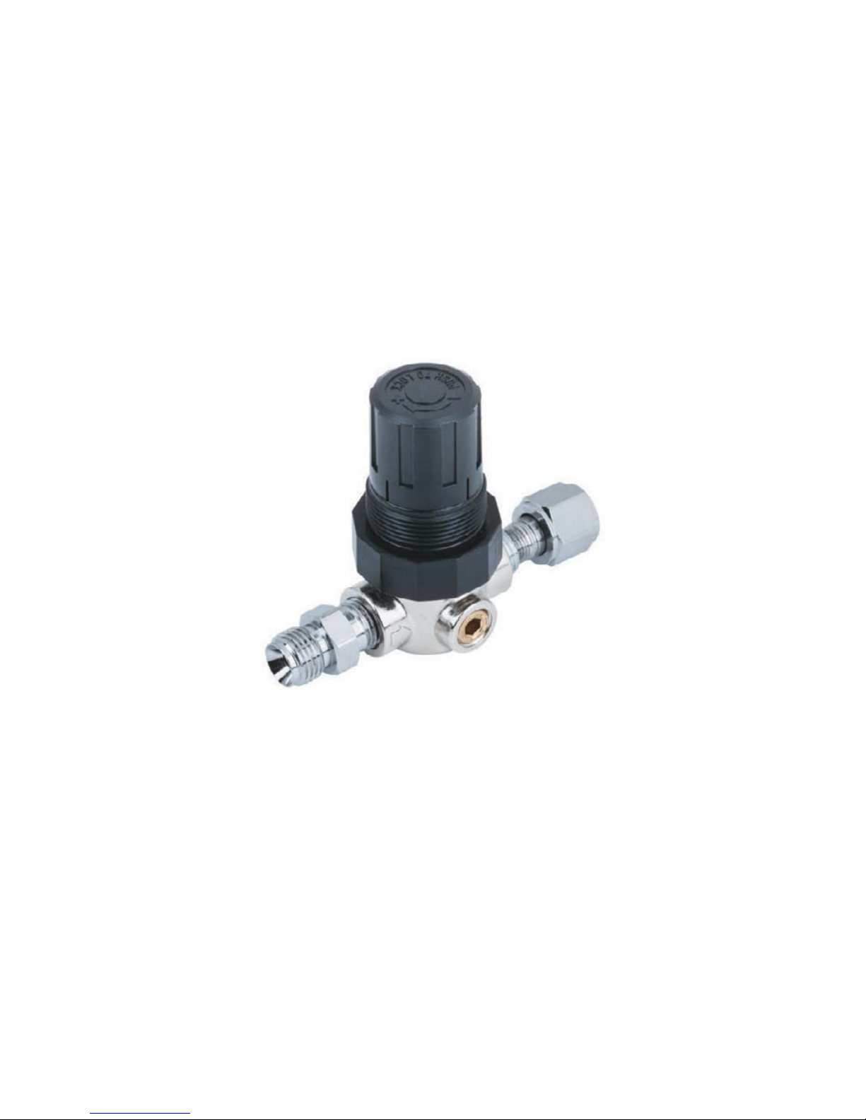
O2 Demand Valve
Resuscitator Quick Connect
(Part# E201)
gure 15
18
Ratio Flow Control
5000-0000-0100 Ratio Flow Control for PC-7...........$140.00
O2 ow rate can be reduced to as low as 1 liter per
minute to match patient breathing volumes while still
maintaining minimum 30% O2 and 70% maximum N2O
gure 16
19
Table of contents
Other Belmed Measuring Instrument manuals

Popular Measuring Instrument manuals by other brands


Flomec
Flomec QSE Series owner's manual

Setra Systems
Setra Systems SRIMV User's installation and operation manual

BIRD
BIRD Termaline 8930 Series Operation manual

Hanna Instruments
Hanna Instruments HI 718 manual

Hydrotechnik
Hydrotechnik MultiSystem 5070 operating instructions

Eastron
Eastron SDM230-LoRaWAN user manual

Grundfos
Grundfos DIT-M Installation and operating instructions

Elenco Electronics
Elenco Electronics TWT-1 instruction manual

Solinst
Solinst 101 Replacement manual

Henlee Electronics
Henlee Electronics 3G-SMKDT1 user manual

Teledyne Lecroy
Teledyne Lecroy frontline SODERA quick start guide

Crystal
Crystal 235 Series operating manual