manuals.online logo
Brands
  1. Home
  2. •
  3. Brands
  4. •
  5. YOKOGAWA
  6. •
  7. Measuring Instrument
  8. •
  9. YOKOGAWA MV100 User manual

YOKOGAWA MV100 User manual

User’s
Manual
Yokogawa Electric Corporation
MobileCorder MV100/MV200
Communication Interface
IM MV100-17E
IM MV100-17E
4th Edition
*MV10017E04*
iIM MV100-17E
Disk No. RE25
4th Edition: February 2002(YK)
All Rights Reserved, Copyright © 2000 Yokogawa Electric Corporation
Forward
Thank you for purchasing the YOKOGAWA MobileCorder MV100/MV200.
This Communication Interface User’s Manual contains information about the Ethernet/
serial interface communication functions. To ensure correct use, please read this
manual thoroughly before operation.
Keep this manual in a safe place for quick reference in the event a question arises.
The following five manuals, including this one, are provided as manuals for the MV100/
MV200.
Manual Name Manual No. Description
MV100 User’s Manual IM MV100-01E Explains all functions and procedures of
the MV100 excluding the communication
functions.
MV200 User’s Manual IM MV200-01E Explains all functions and procedures of
the MV200 excluding the communication
functions.
MV100/MV200 IM MV100-17E This manual. Explains the
Communication communication functions of the Ethernet/
Interface serial interface.
Fieldbus IM 04L02A01-18E Explains the communication functions
Communication of the FOUNDATION Fieldbus interface.
Interface For models with /CF1.
DAQSTANDARD IM 04L02A01-61E Describes the functions and operating
procedures of DAQSTANDARD.
Notes
• This manual describes the communication function of the MV100/MV200 with the
style number “S4.”
• The contents of this manual are subject to change without prior notice as a result of
continuing improvements to the instrument’s performance and functions. The figures
given in this manual may differ from the actual screen.
• Every effort has been made in the preparation of this manual to ensure the accuracy
of its contents. However, should you have any questions or find any errors, please
contact your nearest YOKOGAWA dealer as listed on the back cover of this manual.
• Copying or reproducing all or any part of the contents of this manual without
YOKOGAWA’s permission is strictly prohibited.
• The TCP/IP software used in this product and the documentation for that TCP/IP
software are based in part on BSD Networking Software, Release 1 licensed from The
Regents of the University of California.
Trademarks
• Microsoft, MS-DOS, Windows, and Windows NT are either registered trademarks or
trademarks of Microsoft Corporation in the United States and/or other countries.
• Modbus is a registered trademark of AEG Schneider Automation Incorporated.
• Adobe and Acrobat are trademarks of Adobe Systems incorporated.
• Other company and product names are trademarks or registered trademarks of their
respective holders.
Revisions
• First edition: March 2000 • Fouth edition: February 2002
• Second edition: September 2000
• Third edition: February 2001

ii IM MV100-17E
How to Use this Manual
Structure of the Manual
The structure of this User’s Manual is as follows.
Chapter 1 Overview of the Communication Functions
Describes the relationship between the communication functions and the interface and
provides an outline of the communication functions.
Chapter 2 Using the Ethernet Interface
Describes the specifications and setup procedures of the Ethernet interface. Describes the
FTP client function, Web server function, and e-mail transmission function. Also describes
how to display the log screen.
Chapter 3 Using the Serial Interface (Option)
Describes the functions, specifications, and setup procedures of the serial interface (option).
Two types of serial interfaces, RS-232 and RS-422A/485 are available.
Chapter 4 Using the Modbus Protocol
Describes the specifications and setup procedures of the Modbus protocol and the status
indication screen of the Modbus master.
Chapter 5 Commands
Describes each command that can be used.
Chapter 6 Response
Describes the data format of the panel setup information and measured/computed data that
are output from this instrument.
Chapter 7 Status Report
Describes the status information.
Appendix
Provides an ASCII character code table, the flow of operation when outputting data from MV, a
list of error messages, and the login process.
Index
Provides an index.
Conventions Used in this Manual
Unit
• k Denotes 1000. Example: 5 kg, 100 kHz
• K Denotes 1024. Example: 720 KB (Storage capacity of floppy disks)
Symbols
The following symbols are used in this manual.
Affixed to the instrument. Indicates danger to personnel or
instrument and the operator must refer to the User’s Manual.
The symbol is used in the User’s Manual to indicate the
reference.
WARNING Describes precautions that should be observed to prevent injury
or death to the user.
CAUTION Describes precautions that should be observed to prevent minor
or moderate injury, or damage to the instrument.
Note
Provides important information for the proper operation of the
instrument.
iiiIM MV100-17E
Displayed characters
Alphanumeric characters enclosed with [ ] refer to characters or setting values that are
displayed on the screen.
Symbols used on pages describing operating procedures
On pages that describe the operating procedures in Chapter 2 through 4, the following
symbols are used to distinguish the procedures from their explanations.
Explanation This section describes the setting parameters and the limitations
regarding the procedures.
Procedure Follow the steps indicated with numbers. The procedures are
given with the premise that the user is carrying out the steps for
the time. Depending on the operation, not all steps need to be
taken.
How to Use this Manual
iv IM MV100-17E
Names and Uses of Parts
Front Panel
MV100
O
bil
MC
eOrder
MEDIA FUNC ESC MENUSTART
STOP
DISP/
ENTER
LCD monitor
Soft keys
Press these keys to
select the menu
displayed on the
screen.
DISP/ENTER key
Press this key when confirming the
setting or when closing the entry box.
Arrow keys
Press these keys to move between
the setup items displayed on the
screen.
MENU and FUNC key
After pressing the MENU key, pressing the FUNC key for
approximately 3 s displays the setup menu that is used to
enter the communication configuration menu.
ESC key
Press this key to return to the previous
screen or cancel the new settings.
MV200
1
ABC
POWER
7
STU
FUSE
250V/T1.25A
4
JKL
3
GHI
USER
START
STOP
FUNC ESC MEDIA ENTER
DISP/
MENU
9
YZ
6
PQR
2
DEF
8
0
VWX
5
MNO
Soft keys
Press these keys to select the menu displayed on the screen.
DISP/ENTER key
Press this key when confirming
the setting or when closing the
entry box.
Arrow keys
Press these keys to move
between the setup items
displayed on the screen.
MENU and FUNC key
After pressing the MENU key, pressing the FUNC
key for approximately 3 s displays the setup
menu that is used to enter the communication
configuration menu.
ESC key
Press this key to return to the
previous screen or cancel the
new settings.
Character/number input key
Press these keys to enter characters or
numbers for parameters such as the IP
address, domain name, and server name.
LCD monitor
vIM MV100-17E
Rear Panel
MV100
RS-232 interface connector
A serial communication connector provided on models
with the suffix code /C2.
RS-422-A/485 interface terminal
Serial communication terminals
provided on models with the suffix
code /C3.
Ethernet interface connector
A connector used for Ethernet communications. Comes
standard with the instrument.
MV200
RS-232 interface connector
A serial communication connector provided on
models with the optional code /C2.
RS-422-A/485 interface terminal
Serial communication terminals
provided on models with the
optional code /C3.
Ethernet interface connector
A connector used for Ethernet communications. Comes
standard with the instrument.
Names and Uses of Parts
vi IM MV100-17E
Flow of Operation using the Operation Keys
This section will describe the basic flow of operation when changing the settings of the
MV using the front panel keys.
Settings related to communications are configured in the basic setting mode. The
procedure used to enter the basic setting mode is described in the procedure for each
item. Basic setting mode cannot be entered while data acquisition is in progress or while
computation using the computation function (/M1 option) is in progress.
1. Press the arrow keys to move the cursor onto the desired parameter.
The parameter box containing
the cursor is blue.
2. For parameters whose selections are shown at the bottom of the screen, press
the soft key under the desired selection. For parameters that need characters to
be entered in the entry box, press the [Input] soft key to display the entry box,
enter the characters, and press the DISP/ENTER key.
Parameter selections
(Selection example for [DNS On/Off]
Press either the [On] or [Off] soft key.)
Parameter entry box
(Example of the entry box
for the IP address)
•The boxes containing parameters that have not been changed are displayed in
white.
•The boxes containing parameters that have been changed are displayed in
yellow.
The boxes containing parameters
that have been changed are
displayed in yellow.
The boxes containing parameters
that have not been changed are
displayed in white.
3. Set other parameters as well according to steps 1 and 2.
4. The operation is different when you are confirming or canceling the new
changes (parameter boxes in yellow). See below.
•When confirming the new changes
Press the DISP/ENTER key. The new changes are confirmed and the yellow
parameter boxes change to white. The cursor returns to the parameter at the
upper left portion of the screen (the first parameter on the screen). However,
if the new change is not valid, then the parameter box turns red.
Parameters for which the new
changes that are not valid are
displayed in red.
Names and Uses of Parts
viiIM MV100-17E
Names and Uses of Parts
•When canceling the new changes
Press the ESC key. A window appears for you to confirm the cancellation.
Selecting “YES”and pressing the DISP/ENTER key cancels the new settings
and the screen returns to the previous screen.
Selecting “No”and pressing the DISP/ENTER key does not cancel the new
settings and the screen returns to the original screen.
5. To activate the new settings in the basic setting mode, the settings must be
stored. Pressing the [End] soft key in the basic setting menu* displays a dialog
box that asks you whether or not the new settings are to be stored.
To store the settings, select [Yes]. To not store the settings, select [No]. To
return to the basic setting menu, select [Cancel] by pressing the arrow key, and
press the [DISP/ENTER] key.
* The basic setting menu is the menu that is displayed when the ESC key is pressed
several times after the basic setting parameters are changed.
viii IM MV100-17E
Contents
Forward ................................................................................................................................... i
How to Use this Manual ..................................................................................................................ii
Names and Uses of Parts ..............................................................................................................iv
Chapter 1 Overview of the Communication Functions
1.1 The Relationship between the Communication Functions and the Ethernet/
Serial Interface .................................................................................................................. 1-1
1.2 Explanation of the Functions ............................................................................................. 1-2
Chapter 2 Using the Ethernet Interface
2.1 Ethernet Interface Specifications ...................................................................................... 2-1
2.2 Connecting the Ethernet Interface .................................................................................... 2-2
2.3 Configuring the Ethernet Interface .................................................................................... 2-3
2.4 Checking the Connection Status of the Ethernet Interface ............................................... 2-9
2.5 Setting the FTP Client (Automatic Transfer of Display/Event/Report Data Files) ........... 2-10
2.6 Performing the FTP Test ................................................................................................. 2-16
2.7 Setting the Login/Timeout for Ethernet Communications ................................................ 2-17
2.8 Displaying the Log Screen of the Error, Communication, and FTP................................. 2-22
2.9 Setting the Web Server Function .................................................................................... 2-26
2.10 Using the Monitor Page and Operator Page ................................................................... 2-31
2.11 Setting the E-Mail Transmission Function ....................................................................... 2-38
2.12 Performing an E-Mail Transmission Test ......................................................................... 2-47
2.13 Starting/Stopping E-Mail Transmissions ......................................................................... 2-48
Chapter 3 Using the Serial Interface (Option)
3.1 Serial Interface (Option) Specifications ............................................................................. 3-1
3.2 RS-232 Interface Connector Pin Arrangement and Signal Names, the Connection
Procedure, and Handshaking ............................................................................................ 3-2
3.3 RS-422A/485 Interface Pin Arrangement and Signal Names and the Connection
Procedure.......................................................................................................................... 3-5
3.4 The Bit Structure of One Character and the Operation of the Receive Buffer .................. 3-9
3.5 Configuring the Serial Interface....................................................................................... 3-10
Chapter 4 Using the Modbus Protocol
4.1 Modbus Protocol Specifications ........................................................................................ 4-1
4.2 Register Assignments (Modbus Slave) ............................................................................. 4-2
4.3 Modbus Error Response (Modbus Slave) ......................................................................... 4-3
4.4 Setting the Configuration that is Used When the Modbus Protocol is Used ..................... 4-4
4.5 Setting the Modbus Master Function ................................................................................ 4-7
4.6 Checking the Operating Status of the Modbus Master Function..................................... 4-13
ixIM MV100-17E
Chapter 5 Commands
5.1 Command Syntax.............................................................................................................. 5-1
5.2 A List of Commands .......................................................................................................... 5-3
5.3 Input Range Parameter ..................................................................................................... 5-7
5.4 Setting Commands (Setting) ............................................................................................. 5-9
5.5 Setting Commands (Control)........................................................................................... 5-17
5.6 Basic Setting Commands ................................................................................................ 5-20
5.7 Output Commands (Control) ........................................................................................... 5-29
5.8 Output Commands (Setup, measured, and computed data output) ............................... 5-29
5.9 Output Commands (RS-422A/485 Dedicated Commands) ............................................ 5-32
5.10 Maintenance/Test Commands (Available when using the maintenance/test server function
via Ethernet communications) ......................................................................................... 5-33
5.11 Instrument Information Output Commands (Available when using the instrument
information server function via Ethernet communications) ............................................. 5-34
Chapter 6 Response
6.1 Response Syntax .............................................................................................................. 6-1
6.2 Output Format of ASCII Data ............................................................................................ 6-6
6.3 Output Format of BINARY Data ...................................................................................... 6-20
6.4 Output Format of Instrument Information ........................................................................ 6-25
Chapter 7 Status Report
7.1 Status Information and Filter ............................................................................................. 7-1
7.2 The Bit Structure of the Status Information ....................................................................... 7-2
Appendix
Appendix 1 ASCII Character Codes .....................................................................................App-1
Appendix 2 Output Flow of Internal Memory Data ................................................................App-2
Appendix 3 Output Flow of the File or the File List in the External Storage Medium ............App-4
Appendix 4 Output Flow of FIFO Data ..................................................................................App-6
Appendix 5 Data Dropout (Modbus Master) .........................................................................App-8
Appendix 6 A List of Error Messages ....................................................................................App-9
Appendix 7 Login Process ..................................................................................................App-16
Index
1
2
3
4
5
6
7
App
Index
Contents
1-1IM MV100-17E
Overview of the Communication Functions
1
Chapter 1 Overview of the Communication Functions
1.1 The Relationship between the Communication
Functions and the Ethernet/Serial Interface
The Ethernet interface comes as standard equipment with the instrument. The serial
interface (RS-232, RS-422A/485) is available as an option.
In order to use the various communication functions of the MV, the Ethernet or serial
communications must be configured beforehand.
The following figure illustrates the relationship between the communication functions of
the MV and the Ethernet/serial interface. To use the communication functions of the MV
over the Ethernet/serial interface, protocols* that exist between the function and the
interface must be followed.
* A protocol is a set of rules that govern the communication between two computers over a line
or network.
PC
Connect the MV and
the PC via the serial cable Connect the MV and
the PC via the Ethernet cable
Modbus
slave Modbus
master Setting/Measurement
server
Maintenance/
Test server
FTP
server
Web
server
FTP
client Email
client Instrument
information
server
Login
(User authorization/
grant access rights)
Upper protocol Modbus
protocol
Proprietary protocol
for the MV FTPHTTP SMTP
Lower protocol Serial
communication
control
TCP
IP
Interface Serial interface
(RS-232, RS-422A/485)
Ethernet interface
(10BASE-T)
UDP
The communication functions of the MV
Application
FTP (File Transfer Protocol)
TCP (Transmission Control Protocol)
UDP (User Datagram Protocol)
IP (Internet Protocol)
HTTP (Hyper Text Transfer Protocol)
SMTP (Simple Mail Transfer Protocol)
When you use the serial interface, select one of the following protocols.
•Proprietary protocol for the MV
•Modbus slave protocol
•Modbus master protocol
1-2 IM MV100-17E
1.2 Explanation of the Functions
Describes an outline of the communication functions of the MV.
Modbus slave
•By using the Modbus protocol, measured/computed data written to the MV’s input
register can be read by the PC and communication input data can be written/read
from the MV’s hold register.
•For the Modbus function codes that are supported by the MV, see section 4.1.
•This function can be used only when communicating via the serial interface (option).
•For the settings required to use the functions, see section 4.4.
Data from slave device
Modbus master device
Modbus slave device
Serial communication
MV
Modbus master
•Loads the measured data of other instruments using the Modbus protocol. The
loaded data can be handled as communication input data of the computation function
(/M1 option) on the computation channel.
•Function for writing data to other instruments is not supported.
•For details on the Modbus function codes that are supported, see section 4.1.
•This function can be used only when communicating via the serial interface (option).
•For the settings required in using this function, see section 4.4 and 4.5.
Data from slave device
Modbus master device
Modbus slave device
Serial communication
MV
1-3IM MV100-17E
Overview of the Communication Functions
1
1.2 Explanation of the Functions
Setting/Measurement server
•This function can be used to set almost all of the settings that can be configured using
the front panel keys. However, the power switch cannot be turned ON/OFF. The user
name/password for communications, user name/password for key login, and the
destination of the FTP client function cannot be configured.
•The following types of data can be output.
•Measured/computed data.
•Data in the internal memory or files in the external storage medium.
•Setup information and the status byte.
•A log of operation errors and communications
The measured/computed data can be output in binary or ASCII format to a PC. For
other types of data, ASCII format is used. For the data output format, see chapter 6.
The communication commands that can be used through this function are setting
commands (see sections 5.4 and 5.5), basic setting commands (see sections 5.6),
and output commands (see sections 5.7 to 5.9).
•This function can be used when communicating via the Ethernet or the serial
(optional) interface.
•For the configuration when using Ethernet communications, see sections 2.3 and 2.7.
For the configuration when using serial communications, see section 3.5.
Maintenance/Test server
•Connection information, network information, and other information regarding
Ethernet communications can be output.
•The communication commands that can be used through this function are
maintenance/test commands (see section 5.10).
•This function can be used only when communicating via the Ethernet interface.
•For the configuration required to use this function, see sections 2.3 and 2.7.
FTP server
•You can use a PC to access the MV via FTP. You can perform operations such as
retrieving directory and file lists from the external storage medium of the MV and
transferring and deleting files.
•This function can be used only when communicating via the Ethernet interface.
•For the configuration required to use this function, see sections 2.3 and 2.7.
MV
Files on the storage medium
PC
FTP server
Ethernet
1-4 IM MV100-17E
1.2 Explanation of the Functions
FTP client
Automatic file transfer
•The display data file, event data file, and report data file, that are created in the
internal memory of the MV, can be automatically transferred to a remote FTP
server. The result of the transfer is recorded in the FTP log. The FTP log can be
displayed on the MV’s screen (see paragraph “Displaying error/communications/
FTP logs”described later) or output to a PC using commands.
Display data file/event data file/report data file
FTP server Primary Secondary
Ethernet
Destination (FTP server)
information
Transfer log
(FTP log)
Data file to be
transferred
FTP client
MV
Up to two file transfer destinations (FTP servers) can be specified (primary and
secondary). If the primary server is down, the file is transferred to the secondary
server.
•This function can be used only when communicating via the Ethernet interface.
•For the configuration required to use this function, see sections 2.3 and 2.5.
FTP test
•The file transfer can be checked by transferring a test file from the MV to a remote
FTP server.
•The result of the FTP test can be confirmed on the FTP log screen.
•This function can be used only when communicating via the Ethernet interface.
•For the configuration required to use this function, see section 2.6.
Instrument information server
•The serial number and model of the MV connected to Ethernet can be output.
•The communication commands that can be used through this function are instrument
information output commands (see section 5.11).
•This function can be used only when communicating via the Ethernet interface.
•For the configuration required to use this function, see section 2.3.
1-5IM MV100-17E
Overview of the Communication Functions
1
Login
•This function can be used only when communicating via the Ethernet interface and
when using the setting/measurement server, maintenance/test server, and the FTP
server functions.
•For the configuration required to use this function, see sections 2.3 and 2.7.
•For a description of the login process of the setting/measurement server and
maintenance/test server, see appendix 7.
User authorization
This function allows only registered users to access the MV in order to prevent invalid
access from the network.
•Up to seven names can be registered. You will also specify the access authority
(see below) when registering the name.
•There are limitations on the number of simultaneous connections or
simultaneous uses of the MV from the PC (see section 2.1).
Granting access authority
This function provides access authority (user level) to operate the MV for the
registered users. For example, this prevents user B (user level) from changing the
measurement conditions that were set by user A (administrator level).
•There are two user levels on the MV, user and administrator.
•One administrator and six users can be registered.
•Administrator
An administrator has the authority to use all setting/measurement server
functions, maintenance/test server functions, and FTP server functions.
•User
A user has limited authority to use the setting/measurement server functions,
maintenance/test server functions, and FTP server functions. For the limitation
of commands, see section 5.2.
•Limitations on the use of the setting/measurement server
The user cannot change settings that would change the MV’s operation.
Measurement and setup data can be output.
•Limitations on the use of the maintenance/test server
The user cannot disconnect a connection between another PC and the MV.
The connection between the PC that the user is operating and the MV can
be disconnected.
•Limitations on the use of the FTP server
You cannot save files to the external storage medium of the MV or delete
files on it. Files can be retrieved from the server.
Communication timeout
This function drops the connection if no data transfer is detected between the PC and
the MV over a predetermined period of time. This applies to data transfer at the
application level only (see section 1.1). For example, this function prevents a PC from
being connected to the MV indefinitely which would prohibit other users from making
new connections for data transfer.
1.2 Explanation of the Functions
1-6 IM MV100-17E
Web server
•This function can be used only when communicating via the Ethernet interface.
•The MV screen can be displayed on the browser applications of Microsoft Internet
Explorer.
•The following two screens are available:
•Monitor page: Screen dedicated for monitoring.
•Operator page: You can switch the MV screen. You can also modify and write
messages.
You can set access control (user name and password) on each page.
Switches screens
Arrow keys and
the DISP/ENTER key
Menu
•Refreshes the screen
•Displays the alarm summary
•Displays the measured
/computed data
•Displays logs
•Modifies and writes messages
Selects the screen size
Refreshes the screen automatically
•The screen can be updated at a constant period (approximately 30 s).
•The following information can be displayed.
•Alarm summary
•Measured and computed values of all channels
•Logs (message log, error log, key login/logout log, FTP file transfer log, e-mail
log, and Web operation log)
•For the procedure in setting the Web server function, see section 2.9.
•For operations on the monitor page and operator page, see section 2.10.
E-mail transmission
This function can be used only when communicating via the Ethernet interface.
•Transmitting e-mail messages
E-mail can be automatically transmitted at the following times. You can specify two
groups of destinations and specify the destination for each item. In addition, you can
set a header string for each item.
•When alarm is active/released
Notifies the alarm information.
•During recovery from a power failure
Notifies the time of the power failure and the time of recovery.
•When memory end is detected (See “Fail/Memory End Function (/F1 Option)”
in this section)
Notifies the detection of memory end.
•When an error related to the external storage medium and FTP client occurs
Notifies the error code and message when an error is detected on the external
1.2 Explanation of the Functions
1-7IM MV100-17E
Overview of the Communication Functions
1
storage medium or when the data cannot be saved as the free space on the
storage medium is insufficient. In addition, notifies the error code and message
such as when data transfer fails using the FTP client function.
•At the specified time
Transmits an e-mail message when the specified time is reached. It can be used
to confirm that the system including the network and the e-mail transmission
function is working properly. You can specify the reference time and the e-mail
transmission interval for each destination.
•When report is created (only on models with the optional computation
function (/M1)
Transmits the report.
For the procedure in setting the e-mail transmission function, see section 2.11.
For the e-mail transmission format, see section 2.13.
For the procedure to start/stop e-mail transmission, see section 2.13.
From: MV@yokogawa.co.jp
Date: Sat, 23 Dec 2000 01:00:09 +0900 (JST)
Subject: (MV) Periodic_data
To: [email protected]
LOOP1
Scheduled
Periodic data.
<Host name>
MV
<Time>
Dec.23 01:00:01
Subject
An example of the scheduled e-mail
Header 1
Header 2
•Testing e-mail transmission
•You can send a test message from the MV to the destination to check e-mail
transmissions.
•You can confirm the result of the e-mail transmission test on the e-mail log screen.
•For the procedure in using this function, see section 2.12.
Other functions
Confirming the connection status of the Ethernet interface
•The connection status of the Ethernet interface can be confirmed on the rear panel
and on the screen of the MV.
•For the display position and the meaning of the indicator, see section 2.4.
Keepalive (Extended function of TCP)
•This function forcibly drops the connection if there are no responses to the test
packets that are sent periodically at the TCP level.
•For the configuration required to use this function, see sections 2.3 and 2.7.
Displaying error/communications/FTP/Web operation/e-mail logs
•The operation log can be displayed on the following log screens.
•Error log screen: Operation errors
•Communication log screen: Communication input/output
•FTP log screen: A log of file transfers that were executed using the FTP client
function
•Web operation log screen: Record of operations on the Web server function
•E-mail log screen: Record of e-mail transmissions.
•For the configuration required to use this function, see section 2.8.
1.2 Explanation of the Functions
2-1IM MV100-17E
Using the Ethernet Interface
2
2.1 Ethernet Interface Specifications
Basic Specifications
Electrical and mechanical specifications Conforms to IEEE 802.3
(Ethernet frames conform to the DIX specifications.)
Transmission medium type 10BASE-T
Protocol TCP, IP, UDP, ICMP, ARP
The maximum number of connections and the number of simultaneous uses
The following table indicates the number of simultaneous uses (number of users that
can use the function simultaneously), the maximum number of connections, and the
port number for each function.
Function Maximum Number Number of Port Number*1
of Connections Simultaneous Uses (Fixed)
Administrator User
Setting/ 3 1 2*234260/tcp
measurement
server
Maintenance/ 1 1 1*234261/tcp
test server
FTP server 2 2 2*221/tcp
Instrument –––34264/udp
information
server
*1 Port numbers are fixed.
*2 There are user limitations. For details, see “Granting Access Authority”in section 1.2.
Chapter 2 Using the Ethernet Interface
2-2 IM MV100-17E
2.2 Connecting the Ethernet Interface
When connecting only the MV and a PC
Connect the MV and the PC via a HUB as in the following figure.
PC
Ethernet cable
HUB
10BASE-T straight cable
Ethernet
interface connector
Ethernet
interface connector
(Multiple devices can be
connected by using a hub.)
MV
MV
When connecting to a preexisting network
The following figure illustrates an example in which the MV and a PC are connected to
the network. When connecting the MV or the PC to a preexisting network, the transfer
rate, connector type, etc. must be matched. For details, consult your system or network
administrator.
PC
Ethernet cable
10BASE-T straight cable
Network
Ethernet
interface connector
(Adapters that support
the 10BASE-T (hubs and
routers, for example)
MV
Note
•Depending on the reliability of the network or the volume of network traffic, all the transferred
data may not be retrieved by the PC.
•Communication performance deteriorates if multiple PCs access the recorder simultaneously.
2-3IM MV100-17E
Using the Ethernet Interface
2
2.3 Configuring the Ethernet Interface
Explanation
The following configurations must be made in order to use the Ethernet communication
functions of the MV.
Setting the IP address, subnet mask, default gateway, and DNS
Confirm the settings such as the IP address, subnet mask, default gateway, and DNS
with the administrator of the system or network on which the recorder is to be used.
•IP address
•Set the IP address to assign to the MV. The default setting is “0.0.0.0.”
•The IP address is used to distinguish between the various devices connected to
the Internet when communicating using the TCP/IP protocol. The address is a
32-bit value normally expressed with four values (0 to 255), each separated by a
period as in 192.168.111.24.
•Subnet mask
•Specify the mask that is used to determine the network address from the IP
address. The default setting is “0.0.0.0.”
•Set this value according to the system or the network to which the MV belongs.
In some cases, this setting may not be necessary.
•Default gateway
•Set the IP address of the gateway (router, etc.) used to communicate with other
networks. The default setting is “0.0.0.0.”
•Set this value according to the system or the network to which the MV belongs.
In some cases, this setting may not be necessary.
•DNS (Domain Name System)
You must set the DNS, if you are using a host name to specify the destination
server of the file transfer on an FTP client or the server of the e-mail recipient.
* The DNS is a system that correlates the host name/domain name to the IP address. The
host name/domain name can be used instead of the IP address when accessing the
network. The DNS server manages the database that contains the host name/domain
name and IP address correlation.
•DNS server
•Set the address of the DNS server. The default setting is “0.0.0.0.”
•Up to two DNS servers can be specified (primary and secondary). If the
primary DNS server is down, the secondary server is used to search the host
name/domain name and IP address.
•Host name
Set the MV’s host name using up to 64 alphanumeric characters.
•Domain name
•Set the network domain name to which the MV belongs using up to 64
alphanumeric characters.
•When the destination server of the file transfer or the server of the e-mail
recipient is looked up using the DNS server, this domain name is appended
to the host name as a possible domain name if it is omitted . The destination
name (server name) becomes the “FTP server name”(see section 2.5) or the
“SMTP server name”(see section 2.11).

This manual suits for next models

1

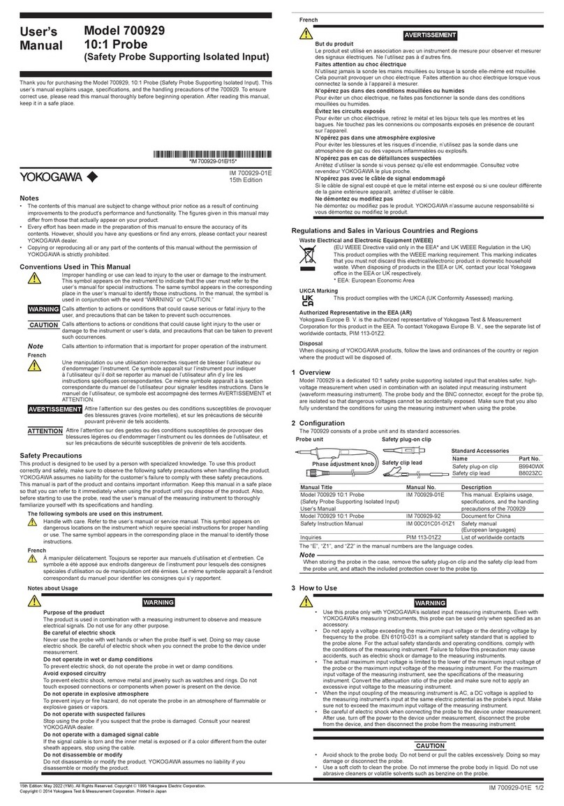
Other YOKOGAWA Measuring Instrument manuals

YOKOGAWA 960 33 User manual

YOKOGAWA

YOKOGAWA 960 33 User manual

YOKOGAWA 700929 User manual

YOKOGAWA

YOKOGAWA 700929 User manual

YOKOGAWA 701957 User manual

YOKOGAWA

YOKOGAWA 701957 User manual

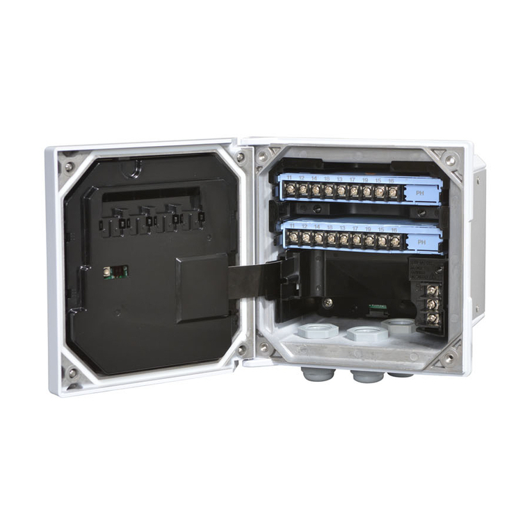
YOKOGAWA FLXA21-P1 Specification sheet

YOKOGAWA

YOKOGAWA FLXA21-P1 Specification sheet

YOKOGAWA FLXA402T User manual

YOKOGAWA

YOKOGAWA FLXA402T User manual

YOKOGAWA DY025 User manual

YOKOGAWA

YOKOGAWA DY025 User manual

YOKOGAWA WN100 User manual

YOKOGAWA

YOKOGAWA WN100 User manual

YOKOGAWA PH72-21-E-AA User manual

YOKOGAWA

YOKOGAWA PH72-21-E-AA User manual

YOKOGAWA TDLS220 User manual

YOKOGAWA

YOKOGAWA TDLS220 User manual

YOKOGAWA IM 2302-E User manual

YOKOGAWA

YOKOGAWA IM 2302-E User manual

YOKOGAWA WT110 User manual

YOKOGAWA

YOKOGAWA WT110 User manual

YOKOGAWA 701944 User manual

YOKOGAWA

YOKOGAWA 701944 User manual

YOKOGAWA 701947 User manual

YOKOGAWA

YOKOGAWA 701947 User manual

YOKOGAWA DTSXL User manual

YOKOGAWA

YOKOGAWA DTSXL User manual

YOKOGAWA 751552 User manual

YOKOGAWA

YOKOGAWA 751552 User manual

YOKOGAWA TA720 User manual

YOKOGAWA

YOKOGAWA TA720 User manual

YOKOGAWA Power Series Plus User manual

YOKOGAWA

YOKOGAWA Power Series Plus User manual

YOKOGAWA 701989 User manual

YOKOGAWA

YOKOGAWA 701989 User manual

YOKOGAWA AQ6375E User manual

YOKOGAWA

YOKOGAWA AQ6375E User manual

YOKOGAWA Power Series Plus User manual

YOKOGAWA

YOKOGAWA Power Series Plus User manual

YOKOGAWA RAGN Manual

YOKOGAWA

YOKOGAWA RAGN Manual

YOKOGAWA TB750G Instruction manual

YOKOGAWA

YOKOGAWA TB750G Instruction manual

YOKOGAWA Power Series Plus IM 249x-COMM Use and care manual

YOKOGAWA

YOKOGAWA Power Series Plus IM 249x-COMM Use and care manual

YOKOGAWA YS1000 Series User manual

YOKOGAWA

YOKOGAWA YS1000 Series User manual

Popular Measuring Instrument manuals by other brands

ELT Sensor MB-350U user guide

ELT Sensor

ELT Sensor MB-350U user guide

ECG CX-920A user manual

ECG

ECG CX-920A user manual

Rohde & Schwarz FSH3 operating manual

Rohde & Schwarz

Rohde & Schwarz FSH3 operating manual

HP E1563A user manual

HP

HP E1563A user manual

Topcon RD-80SA instruction manual

Topcon

Topcon RD-80SA instruction manual

UGT IL-2700 manual

UGT

UGT IL-2700 manual

TSI Instruments DustTrak 8540 Operation and service manual

TSI Instruments

TSI Instruments DustTrak 8540 Operation and service manual

Associated Research HypotULTRA 7800 Operation and service manual

Associated Research

Associated Research HypotULTRA 7800 Operation and service manual

Datatoys XM-DVR Pro manual

Datatoys

Datatoys XM-DVR Pro manual

Swema SwemaFlow 126 operating instructions

Swema

Swema SwemaFlow 126 operating instructions

Hioki 9651 instruction manual

Hioki

Hioki 9651 instruction manual

VDO A2C59519487 instruction sheet

VDO

VDO A2C59519487 instruction sheet

iSystem iC5500 Hardware reference

iSystem

iSystem iC5500 Hardware reference

horiba 9371-10D instruction manual

horiba

horiba 9371-10D instruction manual

PDi SQUID Operation manual

PDi

PDi SQUID Operation manual

Hitachi ZA3000 Series instruction manual

Hitachi

Hitachi ZA3000 Series instruction manual

PCB Piezotronics 3503A102KG Installation and operating manual

PCB Piezotronics

PCB Piezotronics 3503A102KG Installation and operating manual

Endress+Hauser Proline t-mass 65 operating instructions

Endress+Hauser

Endress+Hauser Proline t-mass 65 operating instructions

manuals.online logo
manuals.online logoBrands
  • About & Mission
  • Contact us
  • Privacy Policy
  • Terms and Conditions

Copyright 2025 Manuals.Online. All Rights Reserved.