Huazheng HZ-8700 User manual

HZ-8700
Wireless High Voltage Phase
Sequence Meter
Huazheng Electric Manufacturing (Baoding) Co., Ltd

Contents
I.Roduct Brief..................................................................................................................................1
II.Orking principle...........................................................................................................................1
III、Safety Precautions....................................................................................................................1
IV、Technical characteristics..........................................................................................................2
VI、Short-range nuclear phase......................................................................................................6
VII、Phase sequence detection.....................................................................................................8
VIII、Judgment and analysis of results........................................................................................ 8
IX、Maintenance.............................................................................................................................. 9
X、Packing List...............................................................................................................................10
Appendix A.......................................................................................................................................10
Appendix B.......................................................................................................................................11

1
I.Roduct Brief
HZ-8700 wireless high-voltage phase sequence instrument (hereinafter referred to as
"instrument") is used to determine the phase sequence of three-phase lines and the
nuclear phase of two lines connected to the network or ring network. The instrument is
suitable for measuring the phase sequence and nuclear phase of 6KV~220kV AC
transmission line and secondary live display, and also has the function of high voltage
electrical inspection.
The instrument uses wireless transmission technology, safe and reliable operation, easy
to use.
II.Orking principle
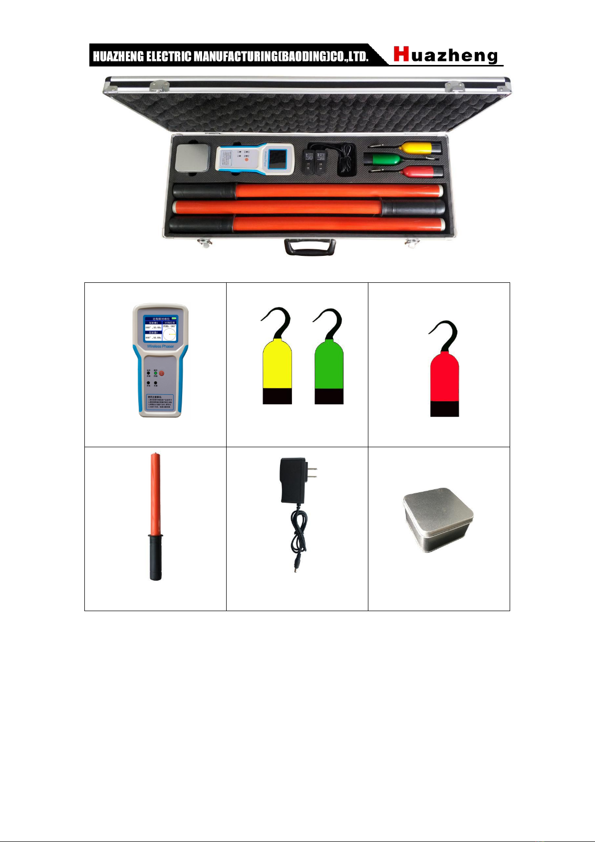
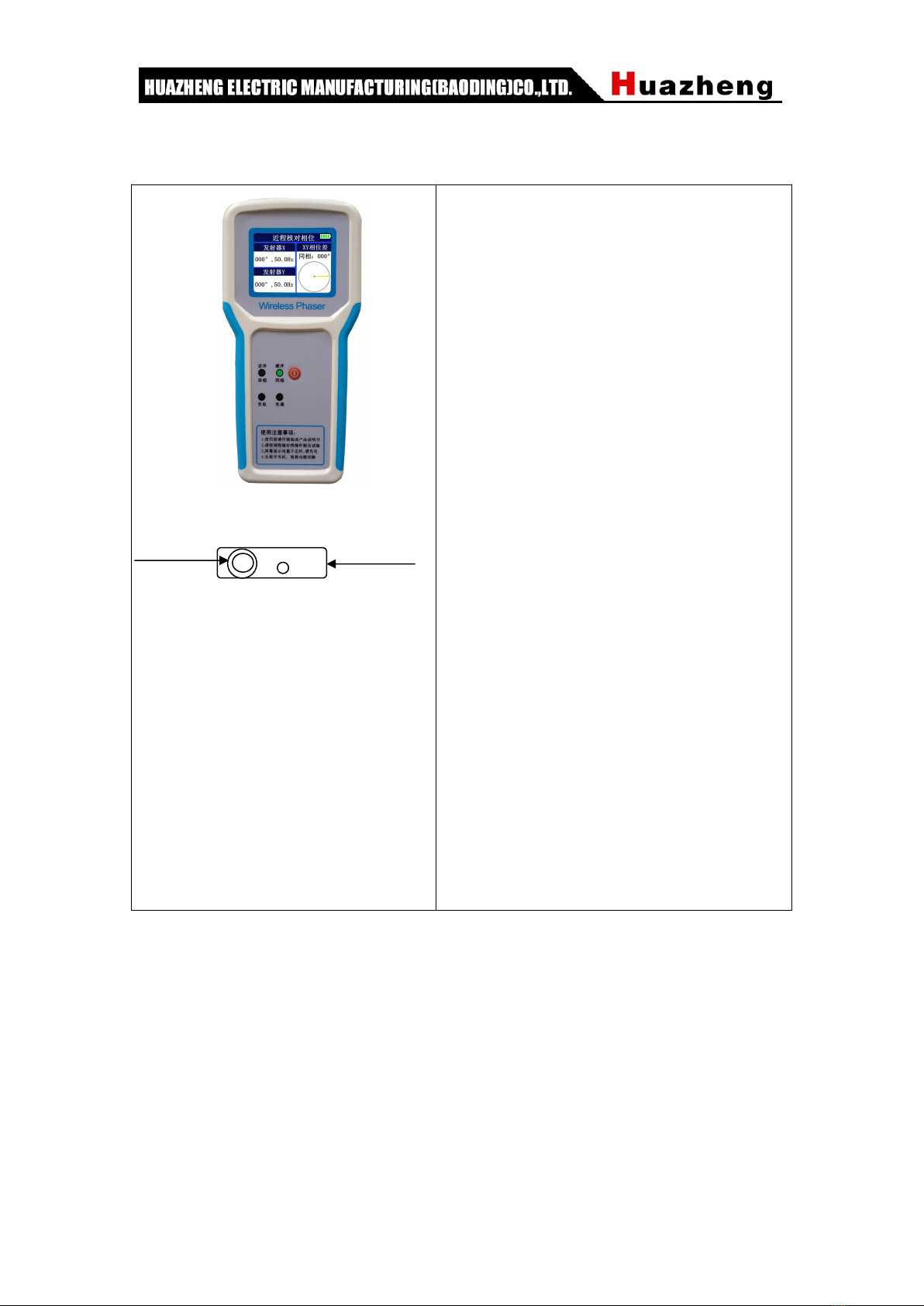
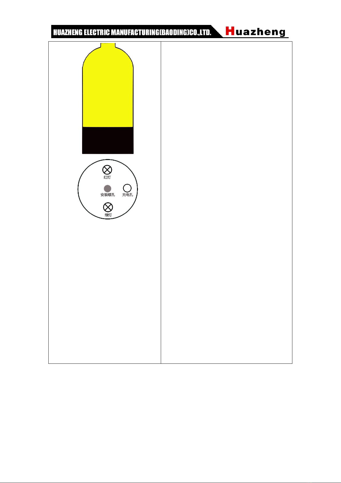
When measuring phase sequence, use X transmitter, Y transmitter, Z transmitter and
receiving host. The three transmitters send the phase and frequency signals of their
respective lines back to the receiving host. The receiving host calculates the phase
difference between the two lines and judges the phase sequence.
In the short-range nuclear phase, only the X transmitter, Y transmitter and receiving host
are used. The two transmitters send the phase and frequency signals of their respective
lines back to the receiving host. The receiving host calculates the phase difference
between the two lines to determine whether they are in phase.
III、Safety Precautions
1. When conducting on-site testing, the operation shall be conducted in accordance with
the safety distance standard for high-voltage testing in the power department.
2. The standard configuration is 3 meters of insulated pole, and the corresponding voltage
level is ≤ 220kV. If the measured line voltage is higher than 220kV, please use an
insulating rod with a length greater than 3 meters.
3. When operating in nuclear phase, do not exceed the position of the handle of the
insulating rod.
Note: The transmitter uses 3.7V rechargeable lithium battery, please do not replace other
batteries.

2
IV、Technical characteristics
1. Accuracy of phase difference: error ≤5°.
2. Frequency accuracy: ±0.1HZ.
3. The measuring range across voltage is 6KV~220kV.
4. The maximum transmission line of sight of the transmitter and the receiving host is
about 100 meters.
5. The 3.2-inch color screen simultaneously displays the phase difference, frequency,
vector diagram and in-phase and out-of-phase results of 2 lines.
6. Judgment of phase sequence results: X leads Y120°, Y leads Z120°, and Z leads X120°
as the order; X lags Y120°, Y lags Z120°, and Z lags X120° as the reverse order.
7. Judgment of the nuclear phase result: the phase difference ≥ 30° is out of phase, and
the phase difference <30° is in phase.
8.The host computer displays battery power, and shuts down automatically after 1 hour of
no operation.
9. The host has a built-in 18650 lithium battery with a battery capacity of 2500mAH. The
transmitter has a built-in 10440 lithium battery with a battery capacity of 450mAH.
10. Leakage current <10uA during high voltage measurement.
11. Transmitter working power consumption <0.1W, receiving host working power
consumption <0.4W.
12. Working environment: -35℃--- +45℃Humidity≤95%RH.
13. Machine weight: about 6.5KG.
14. Instrument packaging size: length 71cm* width 35cmm* height 11cm.
V、Instrument Introduction
(1)Introduction to the appearance of the instrument

3
Component description:
Receiving host
Transmitter X/Y
Emitter z
Insulating rod
Charger
Attachment box

4
(2)Introduction to instrument operation
Charging Hole Horn Hole
(Receiving host)
Indicator light:
(A) The out-of-phase red light is on: the two
lines are out-of-phase/reverse sequence.
(B) The in-phase green light is on: the two
lines are in-phase/sequence.
(C) Charging red light on: charging.
(D) The charging green light is on: the
battery is fully charged.
Button:
1) Press and hold to turn on or off.
2) Short press to switch between short-range
nuclear phase mode and phase sequence
measurement mode.
Supplement:
1) There is a battery indicator in the upper
right corner;
2) There is a charging interface jack at the
bottom.

5
(发射器)
Indicator light:
During measurement: Red light and green
light flash alternately.
When charging: the red light is charging, and
the green light is full.
Buzzer:
The buzzer sounds when it touches the
high-voltage live line, indicating that the line
is live.
3 beeps at startup indicate sufficient power,
2 beeps indicate available power, and
continuous beeps indicate insufficient power,
please charge in time.
Mounting screw holes:
Connected with telescopic insulating rod.
Charging hole:
When charging: Connect the charger.
During self-inspection: Connect the ground
end of the self-inspection test line.
When detecting low voltage: Connect the
ground wire.

6
(3)Instrument self-test method:
The transmitter is connected to the self-test test line, the transmitter starts, the
buzzer sounds, and the red and green indicator lights flash alternately. The receiving
host is turned on, and the corresponding transmitter information is displayed on the
measurement interface. Then the transmitter and the host work normally, as shown
below:
Prompt:
(1) The distance between the two transmitters and the receiving host is greater than 0.5
meters during self-test. When the distance is less than 0.2 meters, only one transmitter may be
connected and the host displays the information of two transmitters. This phenomenon is
normal and does not affect the use of the instrument. When both transmitters are connected,
the instrument display is not affected by short distance.
(2) There is a 2M resistance inside the self-detection test line, and people will not get an
electric shock when they touch the alligator clip during the test.
(3) When the phase difference of the self-detection test is about 180 degrees, reverse any of
the self-test line plugs, the phase difference becomes about 0 degrees, and vice versa.
VI、Short-range nuclear phase
1. Nuclear phase of high voltage transmission line (high voltage nuclear phase)
Connect the X and Y transmitters to the insulating rods and connect them to the
high-voltage line at the same time. When the receiving host is turned on and select the
short-range nuclear phase mode, the nuclear phase results can be displayed and
broadcast. The schematic diagram is as follows:

7
1. Nuclear phase of live display of high-voltage switch cabinet (low-voltage nuclear
phase)
Replace the hooks of the X and Y transmitters with pointed terminals, and insert
the live display, and then insert the DC end of the ground wire into the transmitter
grounding hole (also the charging hole), the crocodile clip is grounded, and the
receiving host is turned on to select the short-range nuclear phase mode. You can
measure. The method of using the transmitter is as follows:
Tip: Because the main function of the live display is to show whether the switchgear is
live, it is not a standard nuclear phase point, and live displays of different manufacturers,
different periods, and different standards will have different degrees of phase shift
problems, and live displays L1, L2, The corresponding relationship between L3 and the

8
bus is not necessarily correct. If the nuclear phase result is abnormal, the nuclear phase
should be performed on the primary line.
VII、Phase sequence detection
Connect the X, Y, and Z transmitters to the three lines with wires, and watch the
measurement results of the receiving host. The instrument is based on the phase angle
of the line measured by the X transmitter and is always displayed as 0°. If the
transmitters Y and Z are 240° and 120° respectively, X leads Y120°, Y leads Z120°, and
Z leads X120°, then the three lines corresponding to X, Y, and Z are in order. If the
transmitters Y and Z are 120° and 240° respectively, X lags Y120°, Y lags Z120°, and Z
lags X120°, then the three lines corresponding to X, Y, and Z are in reverse order. Z
The exchange of any two positions in the three transmitters is a positive sequence. The
operation diagram is as follows:
Prompt:
(1) The X transmitter is used as the reference during the measurement, and its angle is
fixed at 0 degrees. If the receiving host does not receive the signal from the X
transmitter, the angles of the Y and Z transmitters will not be obtained.
(2) If the measured is neither positive sequence nor reverse sequence, it is judged as
disorder, for example, X and Y are connected to the same phase, and Z is connected to
other phases.
VIII、Judgment and analysis of results

9
The nuclear phase results are judged using the national standard A grade standard,
and the phases of different phases are bounded by 30°. When the phase difference is
≥±30°, it is out-of-phase, the voice prompts “out-of-phase”, the screen displays
“out-of-phase”, and the out-of-phase indicator is on. The phase difference <±30° is
in-phase, the voice prompts “in-phase”, the screen displays “in-phase”, and the
in-phase indicator lights. All phase difference results refer to X, and the degree is the
phase where Y leads X.
Tip: When the frequency of the two lines is not the same, you need to use the
quasi-synchronized parallel device to control the frequency phase of the generator, so
that the generator phase and frequency are consistent with the main network before the
power can be connected to the grid. See Appendix B for quasi-synchronization and
self-synchronization operations.
IX、Maintenance
1. When not using for a long time, please store it after fully charging, and it is best to
charge it once a month.
2. This product should not be stored in a humid, high temperature, dusty environment.
3. Before using the insulating rod for the first time, a voltage test shall be carried out,
and a voltage test shall be conducted once a year.

10
X、Packing List
No.
Item
Qty
1
Aluminum alloy chassis
1
2
Receiving host
1
3
launcher
3
4
Telescopic insulated rod (3 meters)
3
5
charger
2
6
Pointed terminal
3
7
Mains dedicated test line
3
8
Ground wire
3
Prompt:
(1) The pointed terminal is a replacement for the hook on the transmitter head.
(2) There is resistance inside the self-testing test line, and people will not get an electric
shock when they touch the crocodile clip during the self-test of the mains.
(3) The ground wire is a straight-through wire and is only used for low voltage (voltage
<1kV) occasions. It is strictly prohibited to use it at high voltage.
Appendix A
Supplementary explanation of insulating rod parameters
Insulation telescopic rods (materials) are made of moisture-proof insulating tubes
produced by military companies. They conform to the IEC/1C78 standard and have the
characteristics of moisture resistance, high pressure resistance, impact resistance, and
bending resistance. The material properties are shown in the table below.

11
Table 1 Mechanical and electrical characteristics of insulating rods
Item
Unit
Index
Martin heat
℃
>200
Impact resistance
MPa/cm
>147
Bending resistance
MPa
>343
Surface resistivity
Ω
>10x1011
Volume resistivity
Ω/cm
>10x1031
Table 2 Insulation pole withstand voltage test parameters
Voltage
(kV)
Length(m)
Power frequency
withstand
voltage(kV)
Time (min)
Result
standard
value
Test
value
6-10
1.5
44
44
1~5
Qualified
35
2.4
80
80
1~5
Qualified
66~110
2.8
254
254
1~5
Qualified
220
3.0
440
440
1~5
Qualified
The product meets the requirements of national standards GB13398-92, GB311.1-311.6-8,
3DL408-91 and the newly promulgated national power industry standard "General
Technical Conditions for Portable Nuclear Phase Apparatus 1kV~110kV for Live Operation
DL/T971-2005".
Appendix B
Synchronization methods of generator grid connection are divided into
quasi-synchronization and self-synchronization:
Quasi-simultaneous paralleling is to add excitation to the generator that has not been
put into the system, and adjust its voltage and frequency. When the parallel condition (that
is, the voltage, frequency, and phase are the same) is met, the generator is put into the
system. If under ideal conditions, make When the outlet switch of the generator is closed,
the circulating current in the stator loop of the generator will be zero, so that no impact of
current and electromagnetic torque will be generated. The quasi-synchronization time is
long, but the impact is small. Large generators should adopt the quasi-synchronization

12
method.
Since they are in parallel at the same time, turn the wheel generator set first. When
the speed rises slightly below the rated speed of the unit, the circuit breaker is closed. At
this time, the power system sends a three-phase impulse current to the stator winding of
the generator to form a rotating magnetic super. The excitation system then sends a DC
current to the rotor winding of the generator to generate a magnetic overload, which
causes the power system to pull the generator into a synchronous operation state. In the
parallel process, the generator suffers certain damage due to the inrush current. The
parallel process is relatively rapid. Since the parallel time is short in the same period, it is
suitable for grid connection of small hydropower.
Table of contents
Other Huazheng Measuring Instrument manuals

Huazheng
Huazheng HZSF-641 User manual

Huazheng
Huazheng HZ-600A User manual

Huazheng
Huazheng CS2670A User manual

Huazheng
Huazheng HZCT-100B User manual

Huazheng
Huazheng HPC500 User manual

Huazheng
Huazheng HZX52AA User manual

Huazheng
Huazheng PHS-2F User manual

Huazheng
Huazheng HZSF-801 User manual

Huazheng
Huazheng HZ2831 User manual

Huazheng
Huazheng EDEKA TC-200 User manual