bemodern 1276 User manual

200662_2 Page 1
User Instructions for Remote Controlled
2kW Rotisserie Effect Fan Heater – Model 1276
T ese instructions s ould be read carefully and retained for future reference.
Tec nical Specification
Parts list Tec nical Data
1. Long screws 4 pcs Model 1276
2. Plastic wall plug 4 pcs Voltage AC 230 240V Fuse 13 amp
3. Remote Control Unit (Inc Battery) 1 Pc Frequency 50Hz
4. Small Screws 4 pcs Power 1800 2000W
5. Small wall Brackets 2 pcs Lamp LED Unit
6. Pebble 1 sets Dimensions 36”
Width 920mm
Height 620mm
Depth 150mm
Fire Installation
Unpack the heater carefully and retain all packaging for future use. Ensure that all packing items are removed and read any warning
labels carefully (see Maintenance Section).
T e appliance must be positioned so t at t e plug is accessible. Only w en you are certain t at you ave completed
t e installation s ould you plug in and switc on at t e wall socket.
CAUTION: In order to avoid a hazard due to inadvertent resetting of the thermal cut out, this appliance must not be supplied
through an external switching device, such as a timer, or connected to a circuit that is regularly switched on and off by the utility.
Important Notes
•These Instructions should be read carefully and retained for the future reference.
•This heater must not be located immediately above a fixed socket outlet.
•Do not use the heater in the immediate surrounds of a bath, a shower, or a swimming pool.
•Do not cover this heater, or obstruct the air inlet or outlet, otherwise there is a risk of overheating.
•The heater must be cooled down completely before any maintenance
•This heater must be fixed against a vertical surface.
•Under no circumstances should the heater be used as a free standing appliance.
•After unpacking, please make sure that the appliance is intact, with no signs of damage caused by transpor
t. If in doubt, do not
use the appliance and contact the Service Centre.
•During normal operation this appliance will emit noise from the internal fan unit.
•If the supply cord is damaged, it must be replaced by the manufacturer, its service agent or similar
ly qualified persons in order
to avoid a hazard.
•This appliance is not intended for use by persons (including children) with reduced physical, sensory or mental capabilities, or
lack of experience and knowledge, unless they have been given supervision or i
nstruction concerning use of the appliance by a
person responsible for their safety. Children should be supervised to ensure that they do not play with the appliance.
Warning: This appliance must be earthed.
The wires in the mains lead connected to this appliance are coloured in accordance with the following code:
GREEN and YELLOW Earth
BLUE Neutral
Brown Live
As the colour of the wires in the mains lead of this appliance may not correspond with the coloured markings identifying the
terminals in your plug, proceed as follows:
•
The wire which is coloured Green and Yellow must be connected to the terminal in the plug which is marked with the letter E or
by the earth symbol or coloured Green or Green and Yellow.
•The wire which is coloured Blue must be connected to the terminal which is marked with the letter N or coloured Black.
•The wire which is coloured Brown must be connected to the terminal which is marked with letter L or coloured Red.
200662_2 Page 2
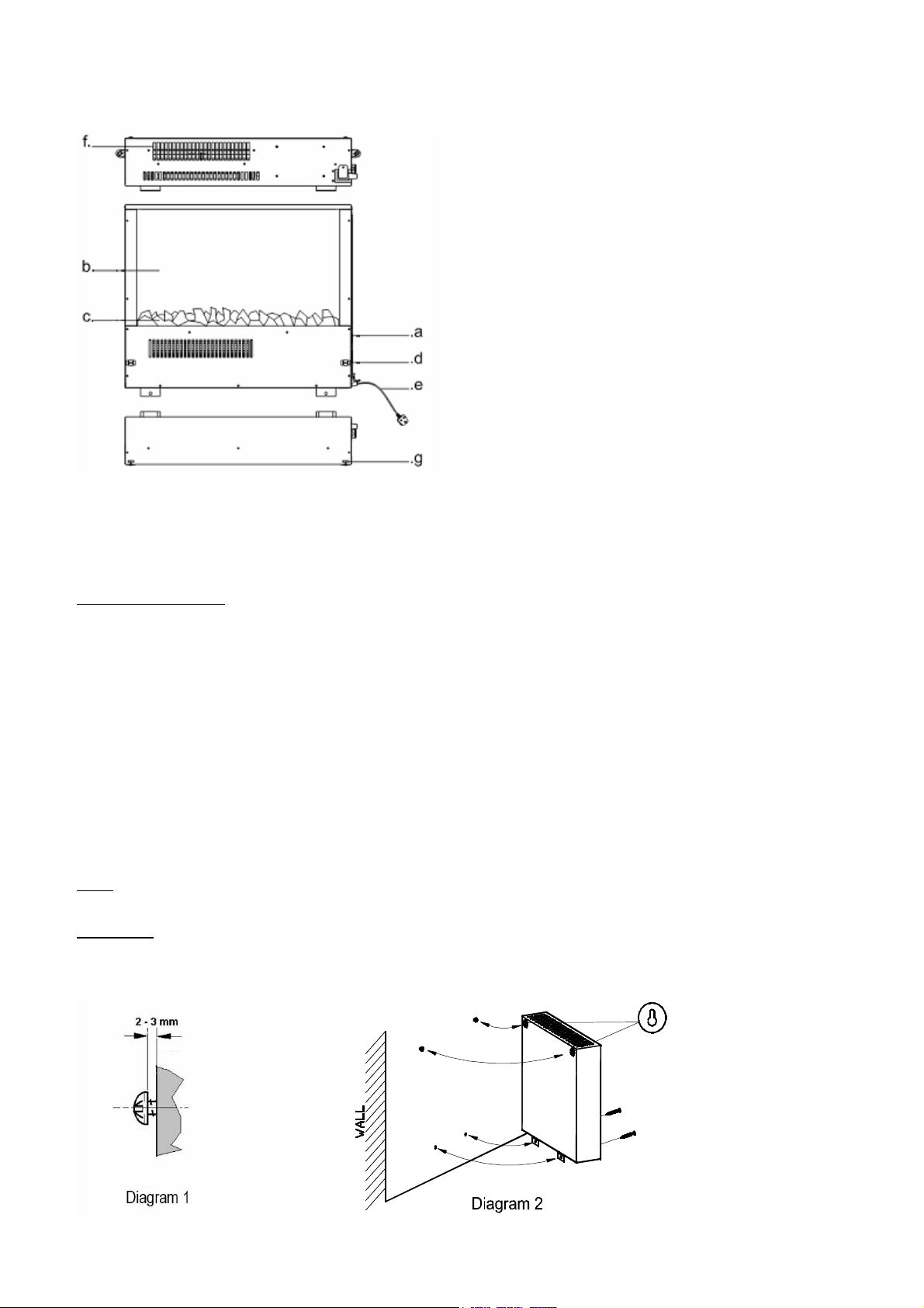
Description of t e appliance (Fig. A)
a. Switches d. Front Panel Clip lock
b. Flame effect Screen e. Power Cord
c. Pebbles f. Air Outlet
g Front Panel Hanging slots
Installation Procedure
a) Affix the wall brackets to the lower part of the back of the fire unit using the 4 small screws as supplied.
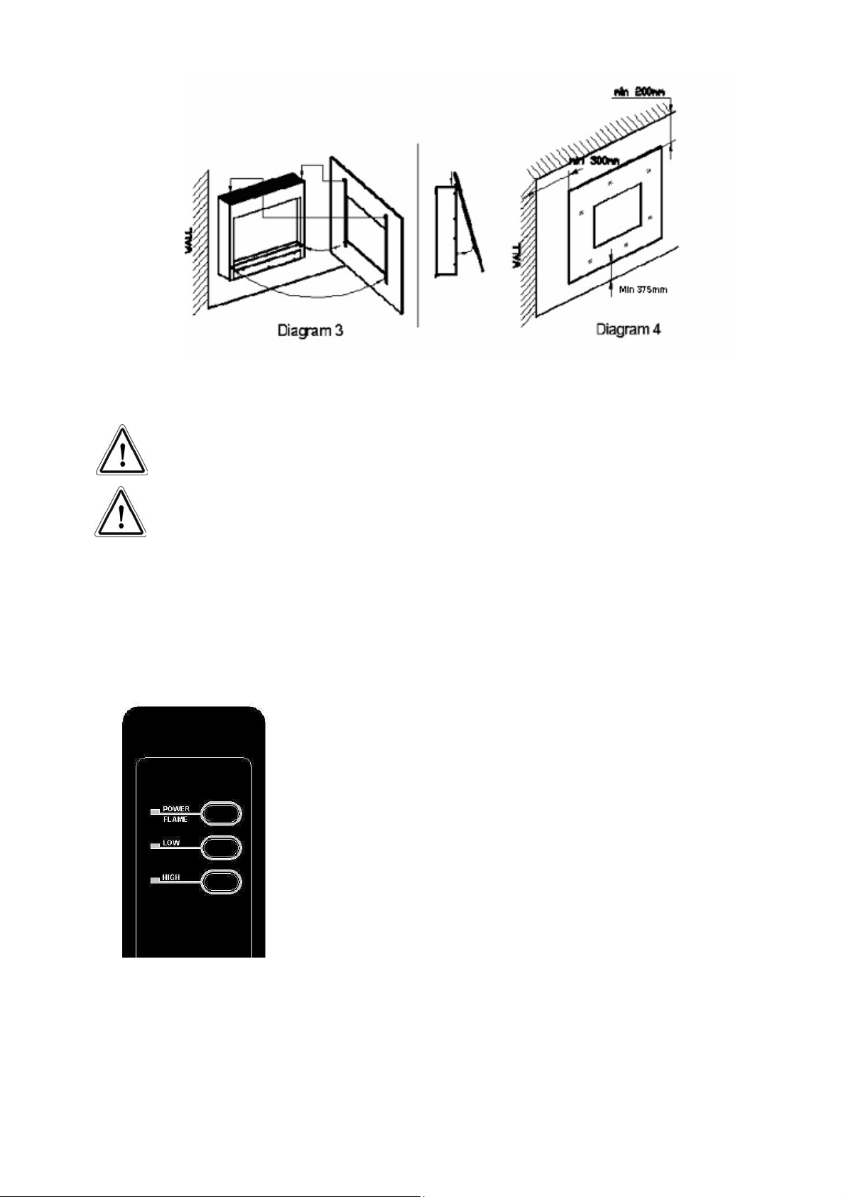
b) When you unpack the front panel, you will find a template. Attach the template carefully to the wall in the chosen position,
taking note of the minimum clearance distance for each type of front panel stated on the template. (See diagram 4)
c) Drill the 4 fixing positions using an 8mm drill bit for the wall plugs supplied or drill the correct size for alterative chosen
fixings if required for the type of wall. (See important note on page 2).
d) Remove the template paper.
e) Install the 2 top fixings into the wall and then install the 2 long screws, screwing them in so the underside of the screw
head stands off the wall by 2 to 3 mm. (See Diagram 1).
f) Locate the heater on the two keyhole slots in the back panel onto the 2 top fixing screws and secure the heater by fixing
the remaining 2 long screws through the lower fixing brackets (See Diagram 2).
g) Place the pebbles supplied evenly on the fuel bed.
h) To fit the front panel, raise the panel into position and locate the returns on the top of the two fixing brackets into the
corresponding hanging bracket slots on the top of the heater (See Diagram 3). Push the bottom of the front panel firmly
into position on the lower clip locks.
Note: The lower support brackets must always be used so as to prevent the heater lifting from the wall mounting bracket.
IMPORTANT If t e screws & wall plugs are not suitable for t e type of wall, t e fixings t at are used must be strong enoug
to support t e weig t of t e fire & t e front panel.
200662_2 Page 3
.
Operation
This appliance can be operated by both remote control and manual button. Once the unit has been properly connected to an earthed electrical
outlet, turn on the main switch located on the right hand side of the appliance. A beep should be heard when the power is first applied.
CAUTION! The unit’s power cord must be connected to a properly grounded and
protected 220-240V outlet. Always use ground fault protection where
required by the electrical code.
WARNING! Do not operate the unit if it is damaged or has malfunctioned. If you
suspect the unit is damaged, please call a qualified service technician to
inspect and to replace any part of the electrical system if necessary.
NOTE! To use both remote and manual functions the manual on/off switch must be in ‘ON’
position.
Remote control
•Ensure that the master on switch (Left hand side) is set to the on (I) position.
•Press the “POWER / FLAME” Button, this turns the flame effect on.
•Pressing the “LOW” button activates the 1KW heat setting, pressing the “LOW”
button again turns off the heating*. To increase the heat output the “HIGH” button
can be pressed to activate the 2Kw output setting.
•Pressing the “HIGH” button activates the 2KW Heat setting, repressing the “HIGH”
button turns off the heating*. To decrease the heat output the “LOW” button can be
pressed to activate the 1Kw output setting.
•When the heater is turned on there will be a brief period (aprox 6 secs) where the
heater will blow cold air. This is to clear the elements of any debris (Dust, Hair etc)
that may have collected on the element. Similarly once the heater is switched off
the fan will blow cold air through the elements ensuring that the elements re cooled
before turning off the fan
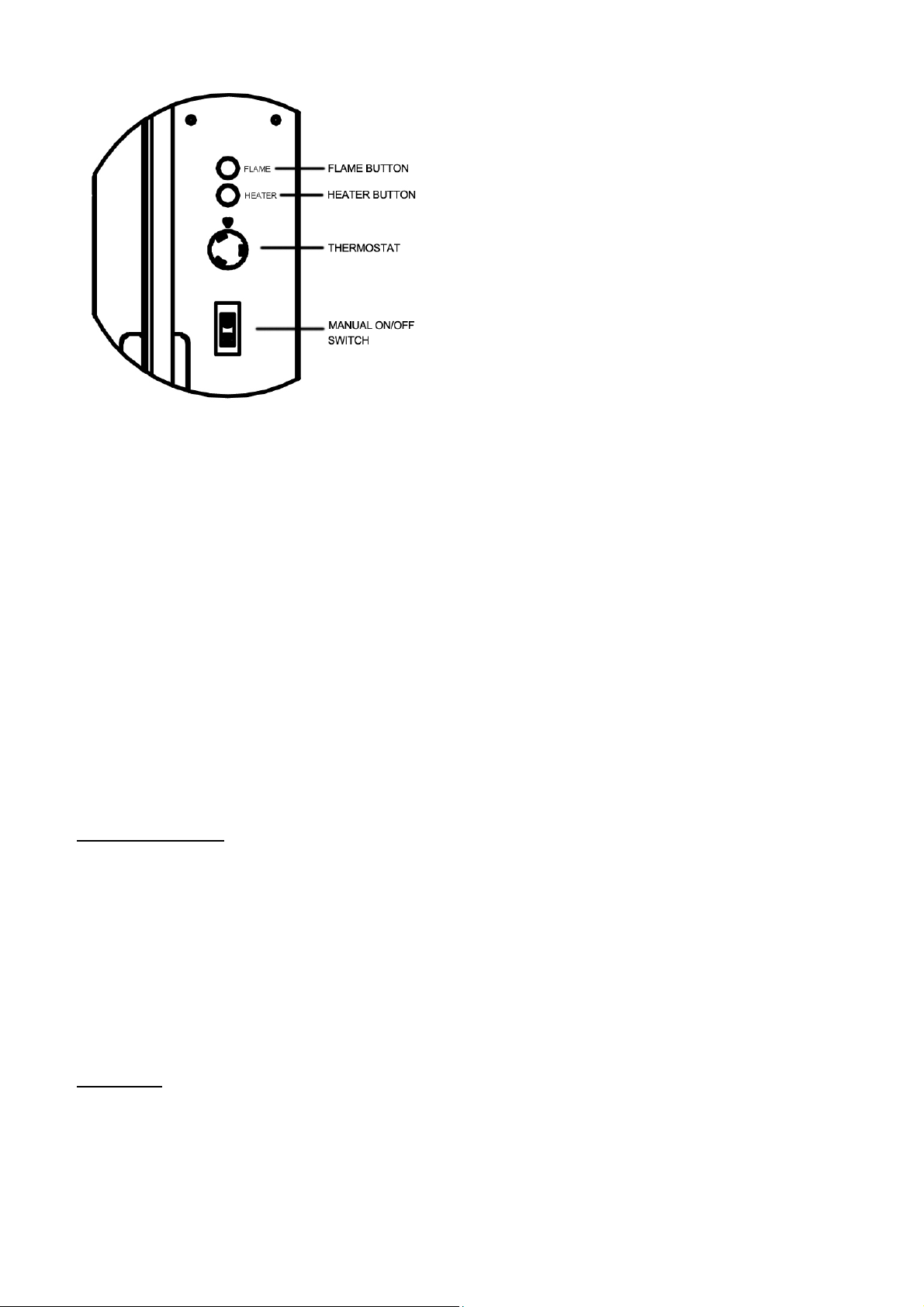
Manual Control
The Manual controls for the fire are located on the right hand side of the fire unit. The controls are FLAME, HEATER, THERMOSTAT and the
MASTER ON AND OFF SWITCH.
200662_2 Page 4
To turn the fire on:
•Ensure the MASTER ON AND OFF SWITCH is in the on (I) Position.
•Press the FLAME BUTTON to turn on the flame effect.
•Pressing the HEATER Button when the flame effect is on will activate the heater function. Repeatedly pressing the heater button
cycles through the following settings. 1KW, 2KW and OFF*
When the heater is turned on there will be a brief period (aprox 6 secs) where the heater will blow cold air. This is to clear the
elements of any debris (Dust, Hair etc) that may have collected on the elements. Similarly oncethe heater is switched off the fan will
blow cold air through the elements ensuring that the elements are cooled before turning off the fan.
Thermostat:
The thermostat is mounted at the right-hand side face of the heater box and can be used to control the heat output to maintain
a constant room temperature to suit user requirements. This will ensure that excessive heat is not produced unnecessarily.
To set the temperature:
The knob is marked with numbers to indicate the maximum and minimum temperature positions. Start with setting 9 and when
the room has reached a desired level turn the knob slowly to left until the thermostat ‘clicks off’. The thermostat will then
maintain the room at the selected level. To increase the temperature, turn knob back to right to a higher setting.
Safety thermal cut-out
This appliance is fitted with an Electric Safety Control (E.S.). This is a safety device, which switches off the fire if, for any reason, the
appliance overheats. The E.S. Control can only be re-set after the appliance has cooled down, in Order to re-set the E.S. Control, proceed as
follows:
Switch off the appliance. Unplug at wall socket and leave for approximately 5-10 minutes.
Plug in switch on appliance and the E.S. Control will re-set.
Ensure that the appliance is functioning correctly. If the E.S. Control switches off again it is advisable to have the appliance checked by a
competent electrician.
Note: -This appliance also has a secondary thermal fuse link incorporated into the heating element that will break the electrical circuit in the
event that the heater fan fails to operate. Unlike the E.S. if this link breaks the fire will not be allowed to re set and the appliance should be
checked by a competent electrician and the fan / element replaced.
CAUTION: In order to avoid a hazard due to inadvertent resetting of the thermal cut out, this appliance must not be supplied through an
external switching device, such as a timer, or connected to a circuit that is regularly switched on and off by the utility.
Maintenance
Warning: Before undertaking any maintenance or cleaning disconnect appliance from main supply. Only competent persons should service /
repair appliances.
200662_2 Page 5
Cleaning the appliance
Note: To prevent scratching of the casing or flame effect screen, this appliance should be cleaned with a damp cloth only.
If the appliance is supplied with a glass front panel, to remove finger prints or other marks, use a soft damp lint freecloth with
a good quality household glass cleaner.
The area around the fire should be kept free of any materials such as lint or house dust (i.e. animal hair/ carpet fibres) that could be drawn into
the internal workings of the appliance and hence affect the performance. We recommend that you clean around the fan grille housing at
regular intervals. This can be done using standard vacuum cleaner and suitable attachment.
Please note if the supply cord on this appliance is damaged it must be replaced by the manufacturers Authorised Service Agent, or a qualified
person to avoid hazard.
Replacing the LED Flame effect:
The LED lighting used in this fire should last for the lifetime of the unit however, if required this component should only be replaced by a
qualified electrician.
Environment
Donot dispose of electrical appliances as unsorted municipal waste, use separate collection facilities. Contact you
local authority for information regarding the collection systems available. If electrical appliances are disposed of in
landfills or dumps, hazardous substances can leak into the groundwater and get into the food chain, damaging your
health and well-being. When replacing old appliances with new ones, the retailer is legally obligated to take back your
old appliance for disposals at least free of charge.
ELECTRIC FIRE GUARANTEE
This fire complies with the European Safety Standards (LVD) EN60335-2-30 and the European Electro Magnetic
Compatibility (EMC) En55015, EN60555-2 and EN60555-3 which covers the essential requirements of the EEC
Directives and 89/336
Customer Services
Tel (0191) 430 0901
Fax (0191) 430 9522
BeModern Ltd. (the ‘Company’) provides a
twelve month
guarantee in respect of electric fire (the ‘Product’) ranges.
1. The twelve month Guarantee applies to:
a. All products in the ranges manufactured by the ‘Company’ (but subject to the exceptions below): where
b. The product has been purchased and installed within the UK and in respect of
c. The initial installation: and in favour of
d. The original purchaser
2. Proof of Purchase must be retained by the Purchaser
3. The twelve month Guarantee does not apply to:
a. Damage or inferior workmanship practices whilst the’ Product’ is being installed
b. Damage caused by mis-use of the ‘Product’ or where normal standards of care and use have not
been complied with.
c. Damage through a malfunction or an inadequately installed electric fire.
d. Damage or defects due to mis-use, accident or unauthorised alterations.
4. During the 1 year after the “Product” has been supplied, the Guarantee covers the making good (whether
by repair or replacement at the Company’s option) of defects arising from defective manufacture of
materials of “Product” covered in Para 1 all at no cost to the purchaser on the proviso:
a. The Product has been installed as Be Modern recommendations
b. The Purchaser uninstalls the Product and makes it available for collection by Be Modern.
This Guarantee does not affect your statutory rights
On requiring service the purchaser should contact the retailer who supplied your product who will assist and
advise you as necessary.
Table of contents
Other bemodern Heater manuals


Popular Heater manuals by other brands

Sealey
Sealey IWMH1500 instructions

Mosebach
Mosebach HX30-B Operation and service manual

AEG Haustechnik
AEG Haustechnik EWH Comfort Series Operating and installation instructions

Consort
Consort CN2F manual

Sears, Roebuck and Co.
Sears, Roebuck and Co. 583.90700 Assembly, operating instructions and parts list

Stanley
Stanley ST-02-230-E instruction manual


