Benchmark AMS4A051 User manual

benchmarkwireline.com
P. O. BOX850
Fax: 281.342.4848
Phone: 281.342.6415
Simonton,Texas 77476
36220 FM1093
AMS4A051 Hoistman's Panel Specification May 2007 Page 1 of 10
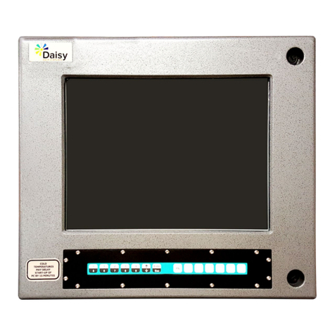
AMS4A051 HOISTMANS DISPLAY PANEL
1.0 GENERAL DESCRIPTION
This panel is designed to acquire and display depth and tension data
from a wireline logging winch unit. The panel provides the operator a
means to set and make adjustments to the data as necessary.
Depth is displayed from data provided from an encoder mounted on a
measuring device. The Quadrature Encoder pulses are passed through
to the acquisition system. The tension data is provided by a load pin and
is also passed through to the acquisition system.

benchmarkwireline.com
P. O. BOX850
Fax: 281.342.4848
Phone: 281.342.6415
Simonton,Texas 77476
36220 FM1093
AMS4A051 Hoistman's Panel Specification May 2007 Page 2 of 10
1.2 FEATURES
-- Digital displays for depth, line speed, and tension
-- Analog incremental tension meter, 4 inch (108 mm) dia., 270 degree.
-- Incremental tension zero push switch.
-- Excessive tension alarm setting allows operator to set tension alarm to a
predetermined value. Contact closure is provided for winch shutdown.
-- Zero Depth button - sets depth to 0. Depressing button again resets
depth to previous setting. Only works when line speed is zero
-- Approaching surface alarm
-- Depth adjust up or down switches. Only works when winch is stopped
-- Load cell zero & calibrate controls. Only works when there is no load on
cable.
-- Depth & tension saved in non-volatile memory at power loss
-- Outputs for Tension and Encoder to interface to an acquisition system.
-- RS232 Interface for additional control and data outputs.
-- Can be set to display either English or Metric units.

benchmarkwireline.com
P. O. BOX850
Fax: 281.342.4848
Phone: 281.342.6415
Simonton,Texas 77476
36220 FM1093
AMS4A051 Hoistman's Panel Specification May 2007 Page 3 of 10
1.3 SPECIFICATIONS
Height: 9.25" 23.5 CM
Width: 10.375" 26.35 CM
Depth: 5” 12.7 CM
Input Power: 12 – 24 vdc +/- 10%
Internal Software coefficients
Wheel Size:
3/16” cable – 2.015 ft.
7/32" cable - 2.017 ft.
1-4” cable – 2.020 ft.
9/32" cable – 2023 ft.
5/16" cable - 2.026 ft.
3/8" cable – 2.031 ft.
Load Cell Angle
3/16” cable – 1.44
7/32" cable – 1.38
1-4” cable - 1.23
9/32" cable – 1.08
5/16" cable - 1.00
3/8" cable – 0.85

benchmarkwireline.com
P. O. BOX850
Fax: 281.342.4848
Phone: 281.342.6415
Simonton,Texas 77476
36220 FM1093
AMS4A051 Hoistman's Panel Specification May 2007 Page 4 of 10
2.0 DETAILED DESCRIPTION OF FEATURES
2.1 FRONT PANEL
2.1.1 INCREMENTAL TENSION METER (M1)
This meter displays the incremental tension. This provides a
more visual display of tension change. Switch SW2 will reset the
meter to the 0 (center) position.
2.1.2 LINE SPEED DISPLAY (D2)
This meter provides a digital display of line speed.
2.1.3 DEPTH DISPLAY (D3)
This meter provides a digital display of depth.

benchmarkwireline.com
P. O. BOX850
Fax: 281.342.4848
Phone: 281.342.6415
Simonton,Texas 77476
36220 FM1093
AMS4A051 Hoistman's Panel Specification May 2007 Page 5 of 10
2.1.4 LINE TENSION DISPLAY (D1)
This meter provides a digital display of total line tension.
2.1.5 ZERO DEPTH (SW6)
Pressing this button will reset the depth to 0. Depressing the
button again will reset the depth to the previous setting. The
Zero Depth button will only work when the line speed is zero (i.e.
winch not moving).
2.1.6 + / - SWITCH (SW 7)
This switch is used for different functions. It is used to change the
depth setting in either an up or down direction. The winch must
be stopped before the depth can be set. In menu mode (see
section 3.0) the switch is used to set menu parameters.
2.1.7 APPROACHING SURFACE LED AND ALARM
This LED and an audible alarm is sounded when the depth is less
than 100' (30 m). This is a warning to the hoist operator that they
are approaching surface and should take care to get the
equipment safely out of the well. When the Cancel button is
depressed, the alarm will stop but the LED will continue to blink.
Once the depth reading is greater than 100' (30 m), both the
alarm and the LED will go off.
2.1.8 ENGLISH / METRIC UNITS
The panel can be changed from English to Metric by installing a
jumper across JP1 or JP2 on the main PCB (refer to 6.4.2). The
scale for the incremental tension meter should also be changed.
2.1.9 PROCESSOR REBOOT
In the event of a panel "lock up" or other malfunction, the
processor in the panel can be rebooted by turning off the panel,
depressing the T-ZERO and T-TEST buttons (SW3 & SW4)
simultaneously then turn the power back on while the buttons are
depressed. When the panel is rebooted, all the menu settings will
be returned to the factory default settings. The tension should be
recalibrated at this time (see section 6.0).
The panel should always be rebooted after new software (eprom)
has been installed.

benchmarkwireline.com
P. O. BOX850
Fax: 281.342.4848
Phone: 281.342.6415
Simonton,Texas 77476
36220 FM1093
AMS4A051 Hoistman's Panel Specification May 2007 Page 6 of 10
2.2 REAR PANEL
2.2.1 FUSE F1
This is a .5 amp slow blow fuse. It is in series with the 12 – 24
vdc power input.
2.2.2 FUSE F2
This is a 2 amp slow blow fuse. It is in series with the encoder
power. It is used to protect the panel from a shorted encoder or
cable. If this fuse is blown, test the encoder and encoder cable
for a possible problem.

benchmarkwireline.com
P. O. BOX850
Fax: 281.342.4848
Phone: 281.342.6415
Simonton,Texas 77476
36220 FM1093
AMS4A051 Hoistman's Panel Specification May 2007 Page 7 of 10
2.2.3 ENCODER IN (J1)
The cable running from the encoder on the measuring head
attaches to this connector. From this connector, the panel
provides 5 vdc power to the encoder and accepts the encoder
quadrature signal input. It is designed to work with standard BEI
encoders or any encoder compatible with BEI standards.
2.2.4 LOAD PIN IN (J2)
This connector is used to connect to the load pin. The panel
provides +/-15VDC power to the load pin and gets the tension
signal input from this connector.
2.2.5 ENCODER OUT (J3)
This connector provides an encoder quadrature data output. This
data can be used to provide depth data to the acquisition system.
The output data is fixed at 120 PPF regardless of line size, wheel
size, or encoder PPR. No encoder power is provided.
2.2.6 TENSION OUT (J4)
This connector provides either a 4-20ma tension signal or a 0-
10vdc tension signal output to the acquisition system.
The 4-20ma signal is provided on pins D and C (gnd). 4 ma = 0
lbs, 20 ma = 12,500 lbs.
The 0-10vdc signal is provided on pins B and C (gnd). 0 vdc = 0
lbs, 5vdc = 6250 lbs, 10vdc = 12,500 lbs.
2.2.7 12 – 24 VDC (J5)
This connector supplies dc power for the panel operation (9 VDC
min, 30 VDC max). The panel can operate on either 12 or 24 vdc
(12 vdc is U.S. truck standard voltage, 24vdc is European truck
standard voltage). Pin A is positive, pin B is negative.
2.2.8 OVER TENSION CONTACT (J7)
This connector provides a connection to the overtension circuit
relay. When an overtension condition is active, the two pins are
connected together. In a normal position the two pins are open.
This feature can be used to interface to the winch unit control
system to provide automatic hoist shutdown when an overtension
condition is reached.

benchmarkwireline.com
P. O. BOX850
Fax: 281.342.4848
Phone: 281.342.6415
Simonton,Texas 77476
36220 FM1093
AMS4A051 Hoistman's Panel Specification May 2007 Page 8 of 10
2.2.9 RS232 SERIAL INTERFACE (J6)
The PC can be used to display depth, tension, and line speed
data from the panel. The PC can also be used to set panel
parameters. See section 6.4 for more details.
To connect the panel to a PC, connect a serial cable from the PC
to J6 on the rear of the panel. The wiring is as follows:
DB9 PIN OUT: 2 = TRANSMIT, 3 = RECEIVE, 5 = GROUND
Run a program such as MS Windows HyperTerm using the
following parameters
BAUD 38,400
BITS 8
PARITYN
STOP 1
HANDSHAKE N
A program is available from BenchMark to display this data (see
figure below).

benchmarkwireline.com
P. O. BOX850
Fax: 281.342.4848
Phone: 281.342.6415
Simonton,Texas 77476
36220 FM1093
AMS4A051 Hoistman's Panel Specification May 2007 Page 9 of 10
MENU COMMANDS
This panel has internal software which allows it to be set for various
configurations. To change the settings, press the MENU button. The feature to
be set will be displayed on the DEPTH display. Press the MENU button again
until the feature you want to set is displayed.
Following is a listing of all the available settings.
OVER TENSION ALARM
CABLE SIZE
DELTA TENSION ALARM
DIFF / INC TENSION
TENSION SHUTDOWN
DELTA TENSION SHUTDOWN
DEPTH ADJUST (Shim)
DEPTH ALARM
ENCODER DIRECTION
STRETCH CORRECTION

benchmarkwireline.com
P. O. BOX850
Fax: 281.342.4848
Phone: 281.342.6415
Simonton,Texas 77476
36220 FM1093
AMS4A051 Hoistman's Panel Specification May 2007 Page 10 of 10
BACK PANEL WIRING DIAGRAM
Table of contents

