Benchmark 1265-000 User manual

READ ALL INSTRUCTIONS BEFORE FIRST USE.
KEEP THIS MANUAL FOR FUTURE REFERENCE.
KEEP AWAY FROM CHILDREN.
WEAR CSA APPROVED
EYE PROTECTION
WEAR EAR
PROTECTION
WEAR A
FACE MASK
5 Year Limited Warranty on tool
JD3596U
E114847

1
PRODUCT SPECIFICATIONS
7-1/4" CIRCULAR SAW
Rating 120V, 60Hz AC
Amperes 15 AMP
Blade Speed 5800 RPM (no load)
Blade Brake Electronic
Arbor 5/8"
Blade 7 ¼", 24T thin kerf carbide blade
Wood Maximum Cutting Depth 2 ⅜ " (60mm) @ 90°
Bevel Angle 1 13/16" (46mm) @ 45°
Weight 13 lbs (5.9Kg)
NEED ASSISTANCE?
Call us on our toll-free customer support line:
1-866-349-8665 (Monday through Friday 9am – 5pm Eastern Standard Time)
• Technical questions
• Replacement parts
• Parts missing from package

2
7-1/4" CIRCULAR SAW 1265-000
TABLE OF CONTENTS
Product Specifications................................................................................... 1
Table of Contents........................................................................................... 2
General Safety Instructions ............................................................................ 3
Eye, Ear & Lung Protection............................................................................. 3
Electrical Safety ............................................................................................ 4
Work Area Safety .......................................................................................... 4
Electrical Safety ............................................................................................ 4
Personal Safety ............................................................................................. 4
Power Tool Use and Care ............................................................................... 5
Service ......................................................................................................... 6
Specific Safety Rules for 15A Circular Saw ..................................................... 6
Causes & Operator Prevention O-F Kickback .................................................. 7
Guidelines for Extension Cords....................................................................... 8
Symbols......................................................................................................... 9
Know Your 7-1/4" Circular Saw..................................................................... 11
Assembly and Operating .............................................................................. 12
Installing Blades .......................................................................................... 12
Setting the Cutting Depth............................................................................. 13
Adjusting the 0° Angle Stop.......................................................................... 14
Installing the Rip Guide ................................................................................ 14
Live Wire Indicator ....................................................................................... 15
LED Work-Light............................................................................................ 15
Trigger Switch.............................................................................................. 16
Materials That You Can Cut .......................................................................... 16
General Cutting............................................................................................ 16
Rip Guide Cutting......................................................................................... 17
Plunge Cutting ............................................................................................. 17
Maintenance ............................................................................................... 18
Exploded View ............................................................................................. 19
Parts List ..................................................................................................... 20
Warranty...................................................................................................... 21
3
GENERAL SAFETY INSTRUCTIONS
WARNING: Before using this tool or any of its accessories, read this
manual and follow all Safety Rules and Operating Instructions. The important
precautions, safeguards and instructions appearing in this manual are not
meant to cover all possible situations. It must be understood that common
sense and caution are factors which cannot be built into the product.
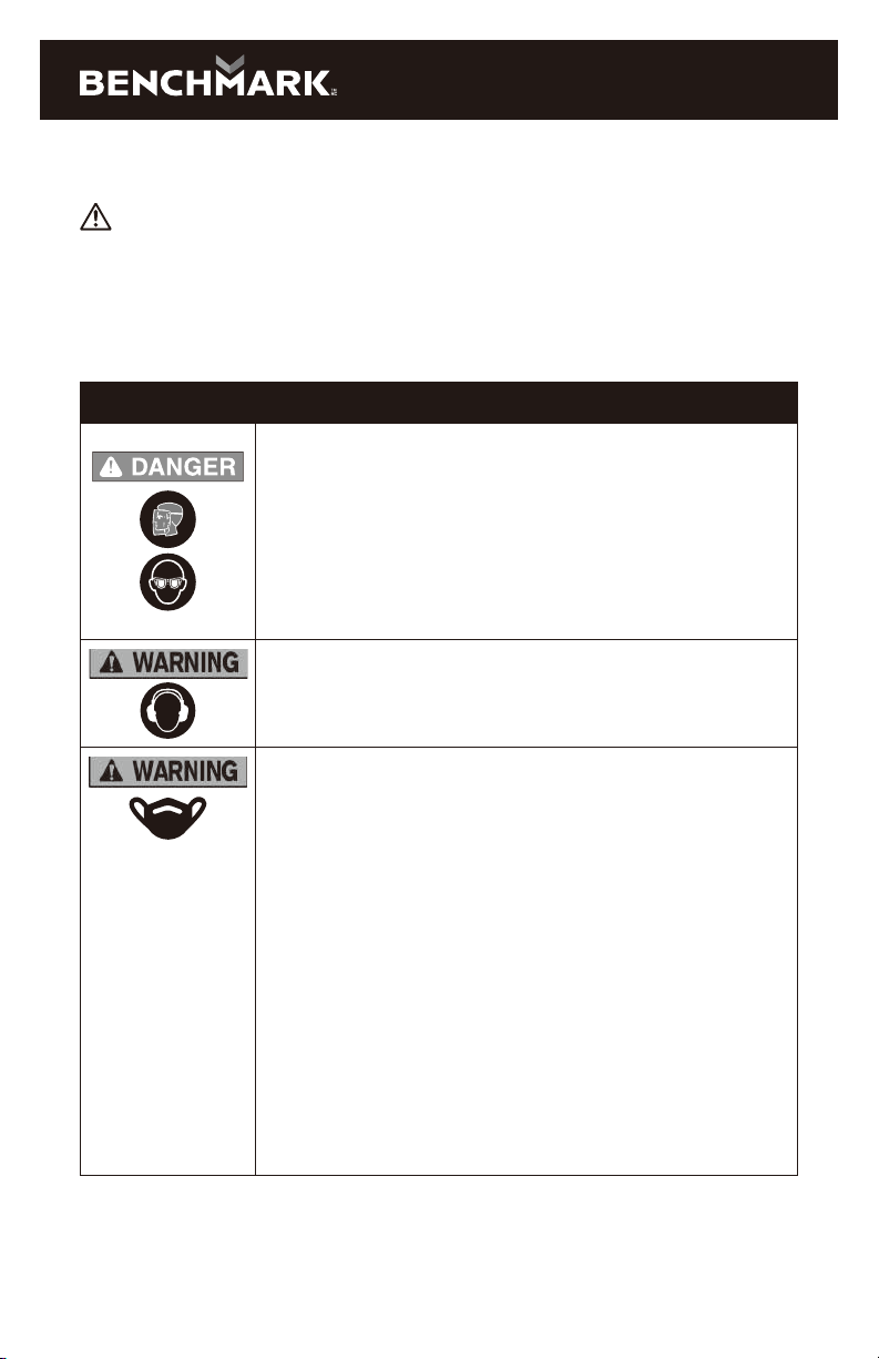
EYE, EAR & LUNG PROTECTION
SYMBOL MEANING
ALWAYS WEAR EYE PROTECTION THAT CONFORMS
WITH CSA Z94.3 or ANSI SAFETY STANDARD Z87.1
FLYING DEBRIS can cause permanent eye damage.
Prescription eyeglasses ARE NOT a replacement for proper
eye protection. The usage of a safety standard compliant
face shield placed over proper safety glasses or goggles
can reduce the risk of facial injury.
Non-compliant eyewear can cause serious injury if broken
during the operation of a power tool.
Use hearing protection, particularly during extended periods
of operation of the tool, or if the operation is noisy.
WEAR A DUST MASK THAT IS DESIGNED TO BE
USED WHEN OPERATING A POWER TOOL IN A
DUSTY ENVIRONMENT.
Dust that is created by power sanding, sawing, grinding,
drilling, and other construction activities may contain
chemicals that are known to cause cancer, birth defects,
or other genetic abnormalities. These chemicals include:
• Lead from lead-based paints
• Crystalline silica from bricks, cement, and other
masonry products
• Arsenic and chromium from chemically treated lumber
The level of risk from exposure to these chemicals varies,
according to how often this type of work is performed. In
order to reduce exposure to these chemicals, work in a
well-ventilated area, and use approved safety equipment,
such as a dust mask that is specifically designed to filter
out microscopic particles.

4
ELECTRICAL SAFETY
WARNING: To avoid electrical hazards, fire hazards or damage to the tool,
use proper circuit protection.
This tool is wired at the factory for 120V AC operation. It must be connected to a
120V AC, 15 A circuit that is protected by a time-delayed fuse or circuit breaker.
To avoid shock or fire, replace power cord immediately if it is worn, cut or damaged
in any way.
WARNING: Read all safety warnings and instructions. Failure to follow the
warnings and instructions may result in electric shock, fire and/or serious injury.
Save all warnings and instructions for future reference.
WORK AREA SAFETY
Keep work area clean and well lit. Cluttered or dark areas invite accidents.
Do not operate power tools in explosive atmospheres, such as in the presence
of flammable liquids, gases or dust. Power tools create sparks which may ignite
the dust or fumes.
Keep children and bystanders away while operating a power tool. Distractions
can cause you to lose control.
ELECTRICAL SAFETY
Power tool plugs must match the outlet. Never modify the plug in any way.
Do not use any adapter plugs with earthed (grounded) power tools. Unmodified
plugs and matching outlets will reduce risk of electric shock.
Avoid body contact with earthed or grounded surfaces such as pipes, radiators,
ranges and refrigerators. There is an increased risk of electric shock if your body is
earthed or grounded.
Do not expose power tools to rain or wet conditions. Water entering a power tool
will increase the risk of electric shock.
Do not abuse the cord. Never use the cord for carrying, pulling or unplugging
the power tool. Keep cord away from heat, oil, sharp edges or moving parts.
Damaged or entangled cords increase the risk of electric shock.
When operating a power tool outdoors, use an extension cord suitable for
outdoor use. Use of a cord suitable for outdoor use reduces the risk of electric
shock.
If operating a power tool in a damp location is unavoidable, use a residual
current device (RCD) protected supply. Use of a ground fault circuit interrupter
(GFCI) reduces the risk of electric shock.
PERSONAL SAFETY
Stay alert, watch what you are doing and use common sense when operating a
power tool. Do not use a power tool while you are tired or under the influence
of drugs, alcohol or medication. A moment of inattention while operating power
tools may result in serious personal injury.
1265-000
7-1/4" CIRCULAR SAW

5
Use personal protective equipment. Always wear eye protection. Protective
equipment such as dust mask, non-skid safety shoes, hard hat, or hearing
protection used for appropriate conditions will reduce personal injuries.
connecting to power source and/or battery pack, picking up or carrying the
tool. Carrying power tools with your finger on the switch or energizing power tools
that have the switch on invites accidents.
Remove any adjusting key or wrench before turning the power tool on.
A wrench or a key left attached to a rotating part of the power tool may result in
personal injury.
Do not overreach. Keep proper footing and balance at all times. This enables
better control of the power tool in unexpected situations.
Dress properly. Do not wear loose clothing or jewellery. Keep your hair, clothing
and gloves away from moving parts. Loose clothes, jewellery or long hair can be
caught in moving parts.
If devices are provided for the connection of dust extraction and collection
facilities, ensure these are connected and properly used. Use of dust collection
can reduce dust-related hazards.
POWER TOOL USE AND CARE
Do not force the power tool. Use the correct power tool for your application.
The correct power tool will do the job better and safer at the rate for which it
was designed.
Any power
tool that cannot be controlled with the switch is dangerous and must be repaired.
Disconnect the plug from the power source and/or the battery pack from the
power tool before making any adjustments, changing accessories, or storing
power tools. Such preventive safety measures reduce the risk of starting the
power tool accidentally.
Store idle power tools out of the reach of children and do not allow persons
unfamiliar with the power tool or these instructions to operate the power tool.
Power tools are dangerous in the hands of untrained users.
Maintain power tools. Check for misalignment or binding of moving parts,
operation. If damaged, have the power tool repaired before use. Many accidents
are caused by poorly maintained power tools.
Keep cutting tools sharp and clean. Properly maintained cutting tools with sharp
cutting edges are less likely to bind and are easier to control.
Use the power tool, accessories and tool bits etc. in accordance with these
instructions, taking into account the working conditions and the work to be
performed.
could result in a hazardous situation.
Hold power tool by insulated gripping surfaces when performing an operation
where the cutting tool may contact hidden wiring or its own cord. Contact with a
"live" wire will make exposed metal parts of the tool "live" and shock the operator.

6
Use clamps or another practical way to secure and support the workpiece to a
stable platform. Holding the work by hand or against your body leaves it unstable
and may lead to loss of control.
SERVICE
Have your power tool serviced by a qualified repair person using only identical
replacement parts. This will ensure that the safety of the power tool is maintained.
Have your power tool serviced by a qualified repair person using only identical
replacement parts. This will ensure that the safety of the power tool is maintained.
SPECIFIC SAFETY RULES FOR 15A CIRCULAR SAW
WARNING: Know your circular saw. Do not plug in the tool until you have
read and understand this Instruction Manual. Learn the tool’s applications
and limitations, as well as the specific potential hazards related to this tool.
Following this rule will reduce the risk of electric shock, fire, or serious injury.
Always wear eye protection. Any power tool can throw foreign objects into
your eyes and cause permanent eye damage. ALWAYS wear safety goggles
(not glasses) that comply with ANSI safety standard Z87.1. Everyday glasses
have only impact resistant lenses. They ARE NOT safety glasses.
WARNING: Glasses or goggles not in compliance with ANSI Z87.1 could
cause serious injury when they break.
Always keep hands out of the path of the saw blade. Avoid awkward hand positions
where a sudden slip could cause your hand to move into the path of the saw blade.
DANGER: Keep hands away from cutting area and the blade. Keep your
second hand on the tool. If both hands are holding the saw, they cannot be cut by
the blade.
Do not reach underneath the workpiece. The guard cannot protect you from the
blade below the workpiece.
Adjust the cutting depth according to the thickness of the workpiece. Less than a
full tooth of the blade teeth should be visible below the workpiece or approximately
3/8" (10 mm).
Never hold piece being cut in your hands or across your leg. Secure the
workpiece to a stable platform. It is important to support the work properly to
minimize body exposure, blade binding, or loss of control.
Hold the tool by its insulated gripping surfaces when performing an operation
where the saw blade may contact hidden wiring or its own cord. Contact with a
“live” wire will make exposed metal parts of the tool “live” and shock the operator.
When ripping always use a straight edge guide. This improves the accuracy of cut
and reduces the chance of the blade binding.
Always use blades with correct size and shape (diamond versus round) of
arbor holes. Blades that do not match the mounting hardware of the saw will run
eccentrically, causing loss of control.
Never use damaged or incorrect blade washers or bolt. The blade washers and
1265-000
7-1/4" CIRCULAR SAW

7
bolt were specially designed for your saw, for optimum performance and safety of
operation.
CAUSES AND OPERATOR PREVENTION OF KICKBACK
Kickback is a sudden reaction to a pinched, bound or misaligned saw blade, causing
an uncontrolled saw to lift up and out of the workpiece toward the operator.
When the blade is pinched or bound tightly by the kerf closing down, the blade stalls
and the motor reaction drives the unit rapidly back toward the operator.
If the blade becomes twisted or misaligned in the cut, the teeth at the back edge of
the blade can dig into the top surface of the wood causing the blade to climb out of
the kerf and jump back toward the operator.
Kickback is the result of saw misuse and/or incorrect operating procedures or
conditions and can be avoided by taking proper precautions as given below:
Maintain a firm grip with both hands on the saw and position your arms to resist
kickback forces. Position your body to the left or right side of the blade, but
not in line with the blade. Kickback could cause the saw to jump backwards, but
kickback forces can be controlled by the operator, if proper precautions are taken.
When the blade is binding, or when interrupting a cut for any reason, release
the trigger and hold the saw motionless in the material until the blade comes
to a complete stop. Never attempt to remove the saw from the work or pull the
saw backward while the blade is in motion or kickback may occur. Investigate
and take corrective actions to eliminate the cause of blade binding.
When restarting a saw in the workpiece, center the saw blade in the kerf and
check that saw teeth are not engaged into the material. If the saw blades are
binding, it may walk up or kickback from the workpiece as the saw is restarted.
Support large panels to minimize the risk of blade pinching and kickback. Large
panels tend to sag under their own weight. Supports must be placed under the
panel on both sides, near the line of cut and near the edge of the panel.
Do not use dull or damaged blades. Unsharpened or improperly set blades
produce narrow kerf causing excessive friction, blade binding and kickback.
Use extra caution when making a “plunge cut” into existing walls or other blind
areas. The protruding blade may cut objects that can cause kickback.
Check the lower guard for proper closing before each use. Do not operate the
saw if the lower guard does not move freely and close instantly. Never clamp
or tie the lower guard into the open position. If the saw is accidentally dropped,
the lower guard may be damaged. Raise the lower guard with the retracting handle
and make sure it moves freely and does not touch the blade or any other part in all
depths of cuts.
Check the operation of the lower guard spring. If the guard and the spring are
not operating properly, they must be serviced before use. The lower guard may
operate sluggishly due to damaged parts, gummy deposits, or a build-up of debris.
The lower guard should be retracted manually only for special cuts such as
“plunge cuts” and “compound cuts”. Raise lower guard by retracting handle and
as soon as the blade enters the material, the lower guard must be released. For all
other sawing, the lower guard should operate automatically.

8
1265-000
Always observe that the lower guard is covering the blade before placing saw
down on the bench or on the floor. An unprotected, coasting blade will cause the
saw to walk backwards, cutting whatever is in its path. Be aware of the time it takes
for the blade to stop after the switch is released.
Never operate the saw while it is being carried to another location. The blade guard
may be open and potentially cause serious injury.
If the switch fails to turn the saw ON or OFF properly, stop using it immediately and
have the saw switch repaired.
Always allow the saw to reach full speed before beginning the cut.
Never use the side of the blade for cutting. When making horizontal cuts, make sure
the weight of the tool is not forcing the side of the blade to do the cutting. This will
reduce the risk of kickback.
Make sure there are no nails orforeign objects in the area of the workpiece to be cut.
Never lay workpiece on hard surfaces like concrete, stone, etc. The protruding
blade may cause tool to jump.
DANGER: To avoid injury from accidental starting, always remove the plug
from the power source before making any adjustments and before installing or
removing a saw blade.
When replacing the blade, make sure the replacement blade is 7 1/4" in diameter
and is rated for 7,000 RPM. Installing an incorrect blade will result in possible
injury and poor cutting action.
After changing a blade or making adjustments make sure the blade clamp screw
is securely tightened. Loose blades and adjustment devices will be violently thrown.
Never touch the blade during or immediately after use. After use the blade is too
hot to be safely touched with bare hands.
GUIDELINES FOR EXTENSION CORDS
Make sure your extension cord is the proper size. When using an extension
cord, be sure to use one heavy enough to carry the current the tool will draw.
An undersized cord will cause a drop in line voltage resulting in loss of power and
overheating. The table on at right shows the correct size to use according to cord
length and nameplate ampere rating. If in doubt, use the next heavier gauge.
The smaller the gauge number the heavier the cord.
Be sure your extension cord is properly wired and in good condition. Always
replace a damaged extension cord or have it repaired by a qualified electrician
before using it. Protect your extension cord from sharp objects, excessive heat and
damp or wet areas.
Use a separate electrical circuit for your power tools. This circuit must not be less
than 14 gauge wire and should be protected with either a 15A time delay fuse or
circuit breaker. Before connecting the power tool to the power source, make sure
the switch is in the OFF position and the power source is the same as indicated on
the nameplate. Running at lower voltage will damage the motor.
7-1/4" CIRCULAR SAW

9
WARNING: Repair or replace damaged or worn extension cords immediately
Select the appropriate extension cord gauge and length using the chart to your right
When operating a power tool outdoors, use an outdoor extension cord marked
“W-A” or “W”. These cords are rated for outdoor use and reduce the risk of
electric shock.
WARNING: Keep the extension cord clear of the working area. Position the
cord so it will not get caught on the workpiece, tools or any other obstructions
while you are working with the power tool
MINIMUM GAUGE (AWG) EXTENSION CORDS (120 V use only)
Ampere Rating Total Length in Feet
More
Than
Not More
Than
7.5 m
(25')
15 m
(50')
30 m
(100')
45 m
(150')
0 6 18 16 16 14
6 10 18 16 14 12
10 12 16 16 14 12
12 16 14 12 Not Applicable
SYMBOLS
WARNING: Some of the following symbols may appear on the saw.
Study these symbols and learn their meaning. Proper interpretation of these
VVOLTS Three-phase alternating current
with neutral
AAmperes Direct current
Hz Hertz noNo load speed
WWatts Alternating or direct current
kW Kilowatts Class II construction
ųF Microfarads Splash-proof construction
LLitres Watertight construction
kg Kilograms Protective grounding at grounding
terminal, Class I tools

10
1265-000
HHours .../min Revolutions or reciprocations per
minute
N/cm2Newtons per
square centimeter ØDiameter
Pa Pascals 0
OPM Oscillations per minute Arrow
MIN Minutes Warning symbol
SSeconds Wear your safety glasses
Alternating current Wear a dust mask
Three-phase alternating
current Wear hearing protection
This symbol designates that this tool os listed with U.S. repuirements by
MET Laboratories, Inc.
UL62841-1,UL62841-2-5;
CSA C22.2#62841-1,CSA C22.2#62841-2-5.
7-1/4" CIRCULAR SAW
JD3596U
E114847
11
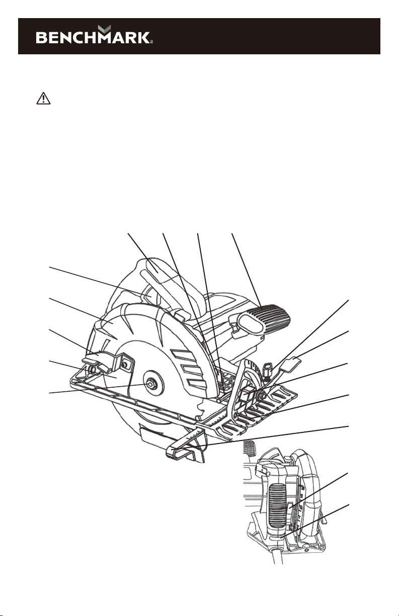
KNOW YOUR 15A 7-1/4" CIRCULAR SAW
WARNING: Before starting please read, understand, and apply the safety
instructions.
FUNCTIONS
1. Main Handle
2. Front Handle
3. LED Work-Light
4. Bevel Gauge
Adjustment Lever
5. Edge Guide
Adjustment Knob
6. 45° Bevel Stop
7. Sole Plate
8. 6 mm Hex Key
9. Rip Guide
10. Blade Screw
11. Lower Blade Guard
12. Blade Guard Lever
13. Upper Blade Guard
14. Trigger Switch
15. Live Wire Indicator
16. Cutting Depth
Locking Lever
5
4
6
7
9
16
15
14
13
12
11
10
1 3 8 2
12
1265-000
ASSEMBLY AND OPERATING
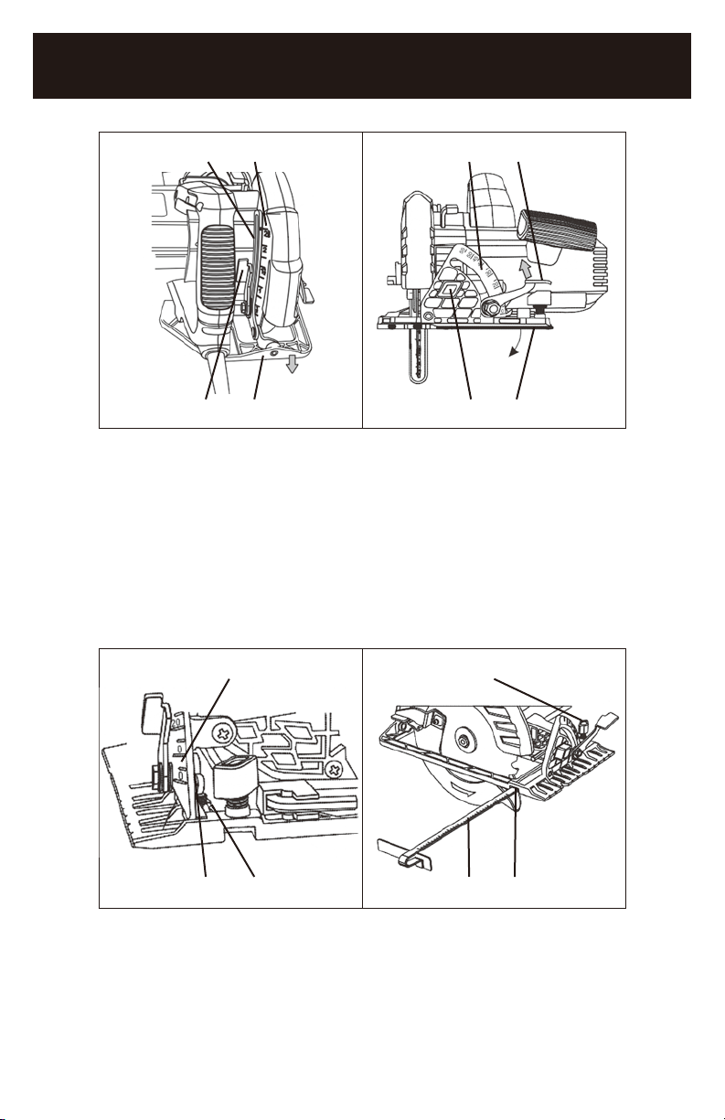
INSTALLING BLADES
WARNING: Always remove the plug from the power source before installing
or removing a blade or adjusting the saw in any way.
1. Place a clean piece of cardboard on a workbench to protect the blade and the
workbench.
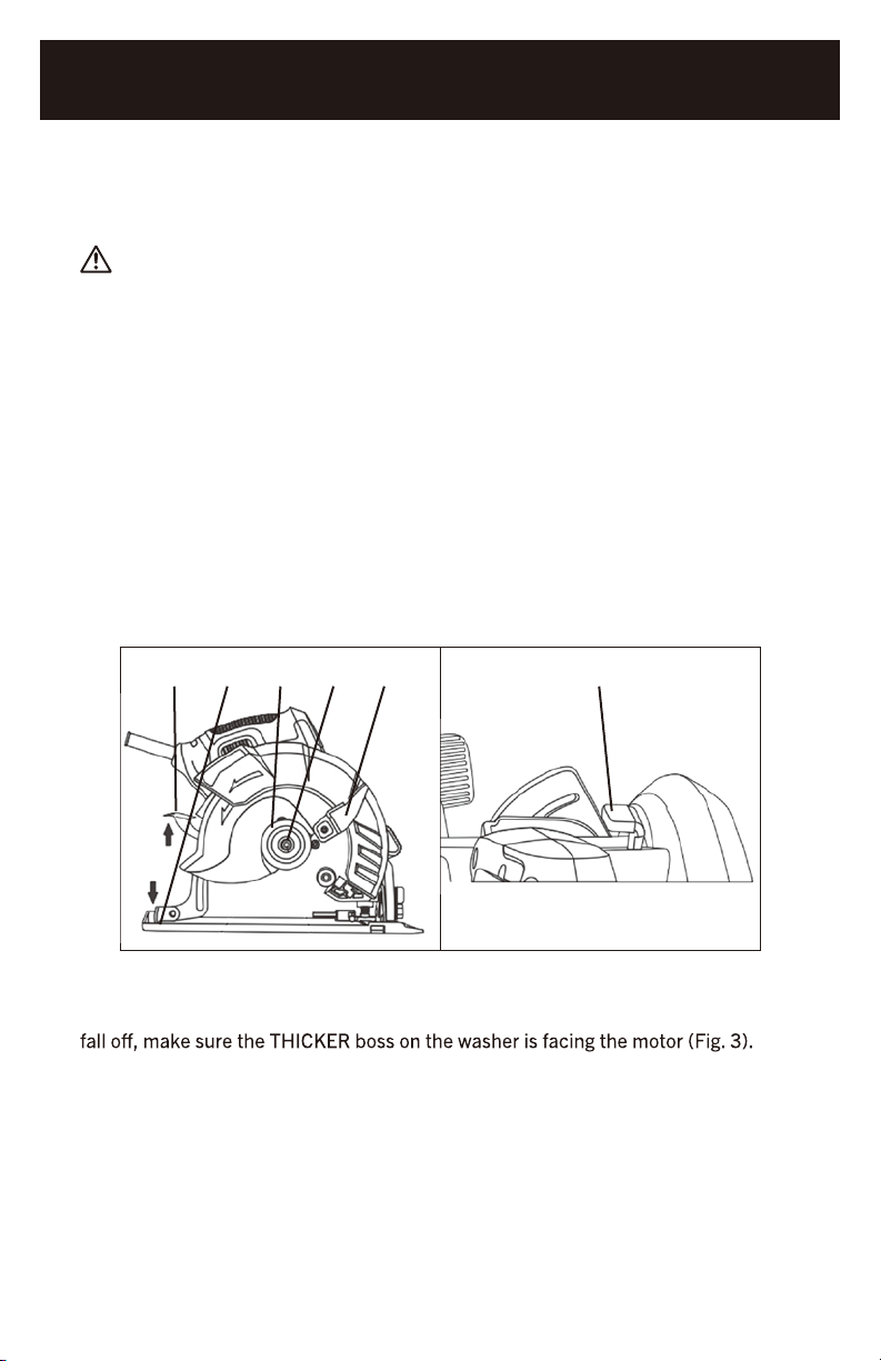
2. Lift the depth adjustment lever (1) and lower the sole plate (2) as far as it will go
(Fig. 1). Press down on the depth adjustment lever to lock the sole plate in its
lower position.
3. Rotate the lower blade guard lever (3) clockwise toward the front of the saw and
carefully place the saw on the cardboard.
4. Insert the 6 MM blade hex key into the blade screw (4).
5. Rotate the blade hex screw counter- clockwise and remove both the blade screw
and the outer blade flange (5).
NOTE: If the arbor turns with the blade screw, press on the blade locking lever (6)
and slowly rotate the blade screw until the locking lever engages the spindle (Fig. 2).
1 2 5 4 3 6
FIG. 1 FIG. 2
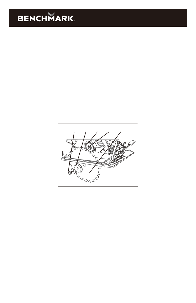
NOTE: Do NOT remove the inner blade flange (7) from the arbor (8). If it should
6. Slide the blade upward through the slot in the sole plate and place the blade
hole onto the arbor.
NOTE: Make sure the blade teeth are pointing toward the front of the saw.
7. Place the outer blade flange (5) onto the arbor and thread the blade screw
(4) into the arbor.
8. Tighten the blade screw.
7-1/4" CIRCULAR SAW
13
NOTE: Press on the blade locking lever (6 Fig. 2) and slowly rotate the blade screw
clockwise until the locking lever engages the spindle. Continue to turn the blade
screw clockwise until the blade is firmly tightened onto the spindle.
When installing a new blade, make sure you follow these precautions:
a) Make sure the teeth at the bottom of the blade are pointing toward the front of
the saw.
b) Check the inner flange washer to make sure the thicker boss is pointing toward
the motor.
c) Place the outer flange washer so the flat surface is against the blade and the
rectangular hole properly mated with the arbor.
d) Make sure the flanged blade screw is NOT cross threaded and is fully tightened
with the wrench provided.
e) Before turning the saw ON, carefully rotate the blade by hand to make sure it
does not wobble.
4 5 7 8 6
FIG. 3
SETTING THE CUTTING DEPTH
The cutting depth of the blade should be set to suit the thickness of the material
being cut. The cutting depth should be approximately 1/8" (3 mm) greater than the
thickness of the material being cut.
1. Lift the depth adjustment locking lever (1) upward (Fig. 4).
2. Pull the sole plate (2) downward until the correct amount of the blade is
protruding below the sole plate.
NOTE: The depth indicator (3) will identify the relative depth of cut on the scale (4).
3. Lock the sole plate at the correct depth by pushing the depth control locking
lever downward.
NOTE: Make a test cut on a scrap workpiece to verify the depth setting.
14
3 4 3 1
1 2 4 2
FIG. 4 FIG. 5
ADJUSTING THE 0° ANGLE STOP
1. Set the bevel angle to 0° (1) (Fig. 6).
2. Use a carpenter’s square to check the angle between the blade and the sole
plate.
3. If the angle is NOT 90°, use a 2.5 mm hex key and adjust the 0° set screw (2)
so the angle is 90° when the 0° stop contacts the set screw.
NOTES: Make a test cut to verify that the saw is cutting at 90°
1 1
1 2 2 3
FIG. 6 FIG. 7
INSTALLING THE RIP GUIDE
1. Loosen the rip guide adjusting knob (1) (Fig. 7).
2. Slide the rip guide rod (2) into the rip guide slot (3). Continue to slide the rip
guide rod across the sole plate and into the rip guide slot under the rip guide
adjusting knob.
1265-000
7-1/4" CIRCULAR SAW

15
3. Adjust the rip guide shoe to the correct distance from the blade and tighten the
rip guide adjusting knob.
LIVE WIRE INDICATOR
The live wire indicator (1) will turn ON when the plug is inserted into a "live" 110V
receptacle (Fig. 8). If the live wire indicator fails to turn on, this indicates the plug is
not inserted into a "live" receptacle.
LED WORK-LIGHT
The LED work-light (1) will turn ON automatically when the tool is plugged into the
power supply (Fig. 9). It will turn OFF when the plug is removed from the power
supply.
1 1
FIG. 8 FIG. 9
WARNING: For safety reasons, the operator must read the sections of this
Owner’s Manual entitled “GENERAL SAFETY WARNINGS“, “POWER TOOL
SAFETY“, “SPECIFIC SAFETY RULES“, “EXTENSION CORD SAFETY“ and
“SYMBOLS” before using this circular saw.
Verify the following every time the circular saw is used:
1. The blade is tight and sharp.
2. All adjustments are tight.
3. The workpiece is properly secured.
4. Safety glasses and hearing protection are being worn.
Failure to adhere to these safety rules can greatly increase the chances of
serious injury.

16
TRIGGER SWITCH
1. To turn the saw ON, squeeze the trigger switch (1) (Fig. 9).
WARNING: Never carry the saw with your finger on the trigger switch.
The saw could be accidentally started and cause severe personal injury.
2. To turn the saw OFF, release the trigger switch.
1
FIG. 9
MATERIALS THAT YOU CAN CUT
of materials. Some of the materials include:
• Wood products such as lumber, hardwood, plywood, composite board
and paneling
• Drywall
• Masonite and plastic
NOTE:
with carbide- tipped teeth cut better and stay sharp longer. Tooth count and
configuration are also important. High tooth counts cut slower, and are best suited
for making smooth cuts on thinner materials such as paneling. Use the correct
blade for your application.
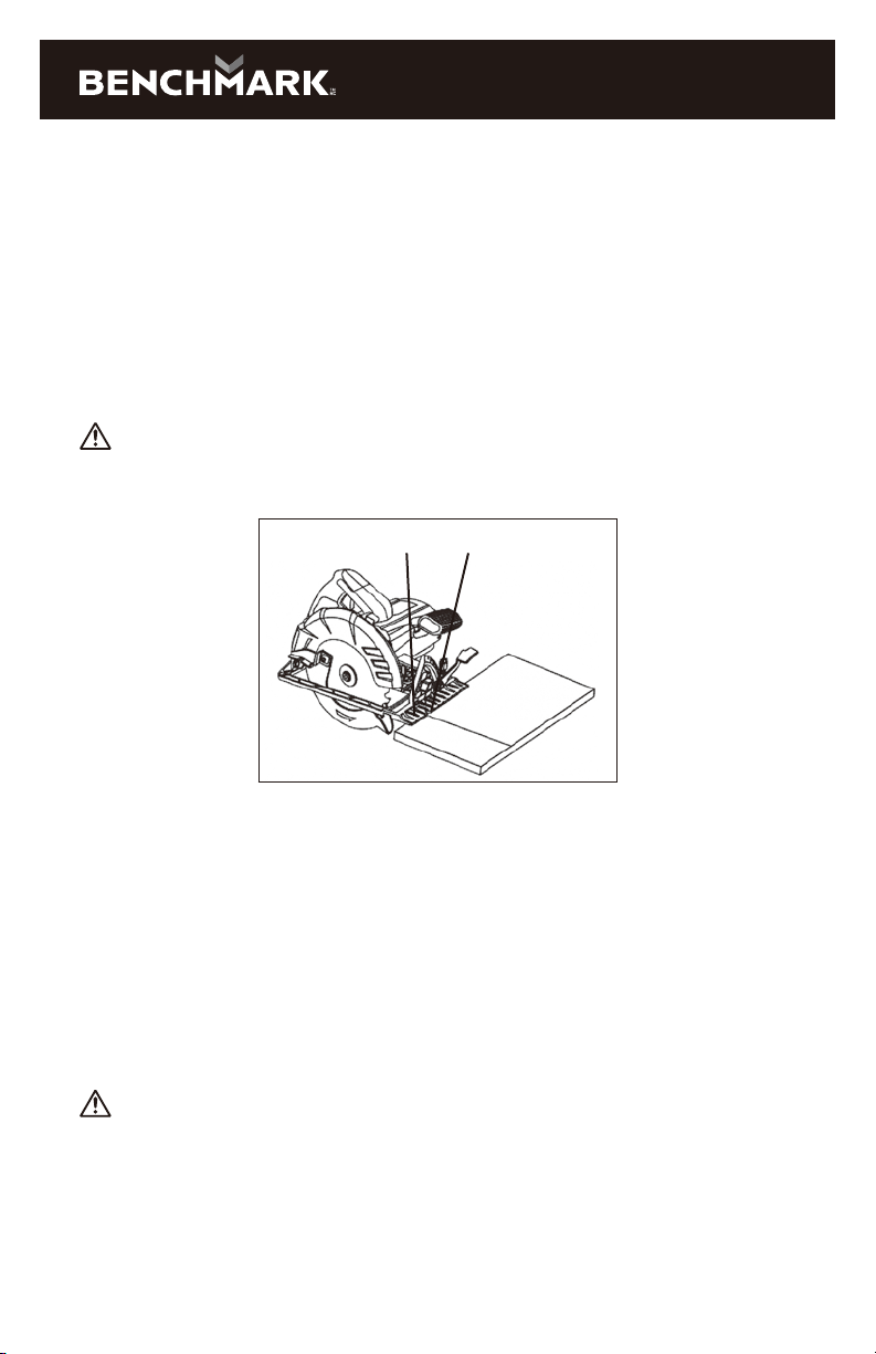
GENERAL CUTTING
1. Make any adjustments to the saw before installing the blade.Adjustments include
cutting depth, cutting angle and ripguide(if installed).
2. Clearly mark the workpiece to locate the position of the cut.
3. Hold a smaller workpiece with a vise. Clamp alarger workpiece to a workbench or
table.
DANGER:Any workpiecethat is not adequately clamped in place may come
loose andcause serious injury. Never hold the workpiece in your hand.
4. Make sure there are no nails, screws, clamps or foreign materials in the path
of the saw blade.
1265-000
7-1/4" CIRCULAR SAW
17
5. With both hands firmly gripping the saw, and with the blade NOT in contact with
the surface to be cut, start the saw by squeezing the trigger switch.
6. Once the saw has reached full speed, place the front edge of the sole plate on the
workpiece andgradually bring the moving blade into contact with the workpiece
at the appropriate location.
NOTE: To align the saw blade with the cutting mark, use the guide marks on the
front of the sole plate (Fig. 10). Use the 0° cutting mark (1) for right angle cuts.
Use only the 45° mark (2) for 45° cuts. The 45° mark will allow for the extra material
needed for the angle cut. Always make a test cut on ascrap workpiece before
cutting the new material.
WARNING: Do not force the circular saw. Use only enough force to keep the
blade cutting at full speed. Excessive pressure on the blade will cause it to slow
down and overheat, resulting in poor cut quality and damage to the motor.
1 2
FIG. 10
RIP GUIDE CUTTING
1. Set the rip guide foot at the required width (Fig. 7).
NOTE: When starting the cut, make sure the blade is parallel to the edge of the
workpiece and the rip guide foot is against the edge of the workpiece.
2. Proceed with the cut as outlined in “GENERAL CUTTING” above.
NOTE: As you move the saw through the workpiece, make sure the guide foot stays
in contact with the workpiece.
PLUNGE CUTTING
WARNING: To avoid loss of control, damage to the blade or damage to
the workpiece, always use extreme caution when making plunge cuts. It is not
recommended to plunge cut any material other than wood.
1. To plunge cut inside the edges of a workpiece, clearly mark the cutting line on
the workpiece.
2. Set the bevel angle to 0° (Fig. 5).

18
3. Lift the cutting depth locking lever upward to allow the blade to rise above the
bottom of the sole plate so the blade will NOT contact the workpiece (Fig. 4).
Do NOT lock the cutting depth locking lever.
4. Set the saw on the workpiece (1) so the sole plate is flat on the workpiece.
(Fig. 11).
5. Open the blade guard by rotating the blade guard lever (2) forward.
6. Align the saw blade with the cutting line (3) using the 0° cutting mark on the
sole plate.
NOTE: Make sure the saw blade is inside the area to be cut out.
7. Start the saw and slowly lower the blade onto the workpiece while holding the
blade guard lever forward to allow the blade to cut into the workpiece (Fig. 12).
Allow the blade to cut through the wood.
8. Continue lowering the blade into the workpiece until the full cutting depth has
been achieved. Continue sawing toward the cutting line and complete the cut as
required.
1 2 3
FIG. 11 FIG. 12
MAINTENANCE
WARNING: When servicing, use only identical replacement parts. The use of
any other part may create a hazard or cause product damage.
DO NOT use solvents when cleaning plastic parts. Plastics are susceptible to
damage from various types of commercial solvents and may be damaged by their
use. Use a clean cloth to remove dirt, dust, oil, grease etc.
WARNING: Do not allow brake fluids, gasoline, petroleum-based products,
penetrating oils, etc. to come into contact with plastic parts. They contain
chemicals that can damage, weaken or destroy plastic.
DO NOT abuse power tools. Abusive practices can damage the tool and the
workpiece.
WARNING: DO NOT attempt to modify tools or create accessories. Any such
alteration or modification is misuse and could result in a hazardous condition
leading to possible serious injury. It will also void the warranty.
1265-000
7-1/4" CIRCULAR SAW
19
It has been found that electric tools are subjected to accelerated wear and
possible premature failure when they are used on fiberglass boats and sports
cars, wallboard, spackling compounds or plaster. The chips and grindings from
these materials are highly abrasive to electric tool parts such as bearings, brushes,
commutators, etc. Consequently, it is not recommended that this tool be used
for extended work on any fiberglass material, wallboard, spackling compounds or
plaster. During any use on these materials it is extremely important that the tool is
cleaned frequently by blowing it out with an air jet.
WARNING: Always wear safety goggles or safety glasses with side shields
during all cutting operations. It is critical that you also wear safety goggles or
safety glasses with dust out of the circular saw with an air jet. Failure to take
these safety precautions could result in permanent eye or lung damage.
If the motor brushes require replacement, contact the toll-free customer support
line: 1-866-349-8665 Monday – Friday from 9am to 5pm Eastern Standard Time
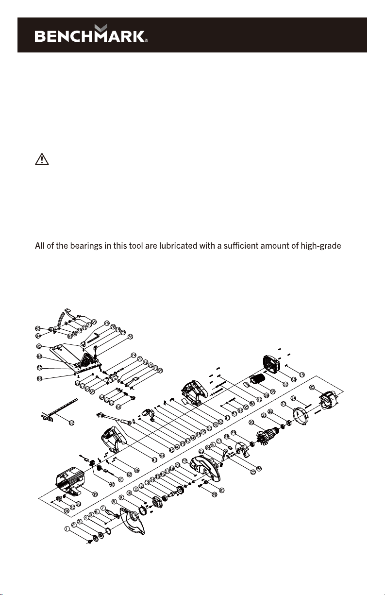
LUBRICATION
lubricant for the life of the unit under normal operating conditions. Therefore, no
further lubrication is required.
EXPLODED VIEW
Table of contents
Other Benchmark Saw manuals

Benchmark
Benchmark 1345-300 User manual

Benchmark
Benchmark 1347-001 User manual

Benchmark
Benchmark 1270-205 User manual

Benchmark
Benchmark 1265-002 User manual

Benchmark
Benchmark 1347-006 User manual

Benchmark
Benchmark 1265-001 User manual

Benchmark
Benchmark 1270-204 User manual

Benchmark
Benchmark 1270-001 User manual

Benchmark
Benchmark 1347-100 User manual

Benchmark
Benchmark 1347-005 User manual


