Benchmark 1347-001 User manual

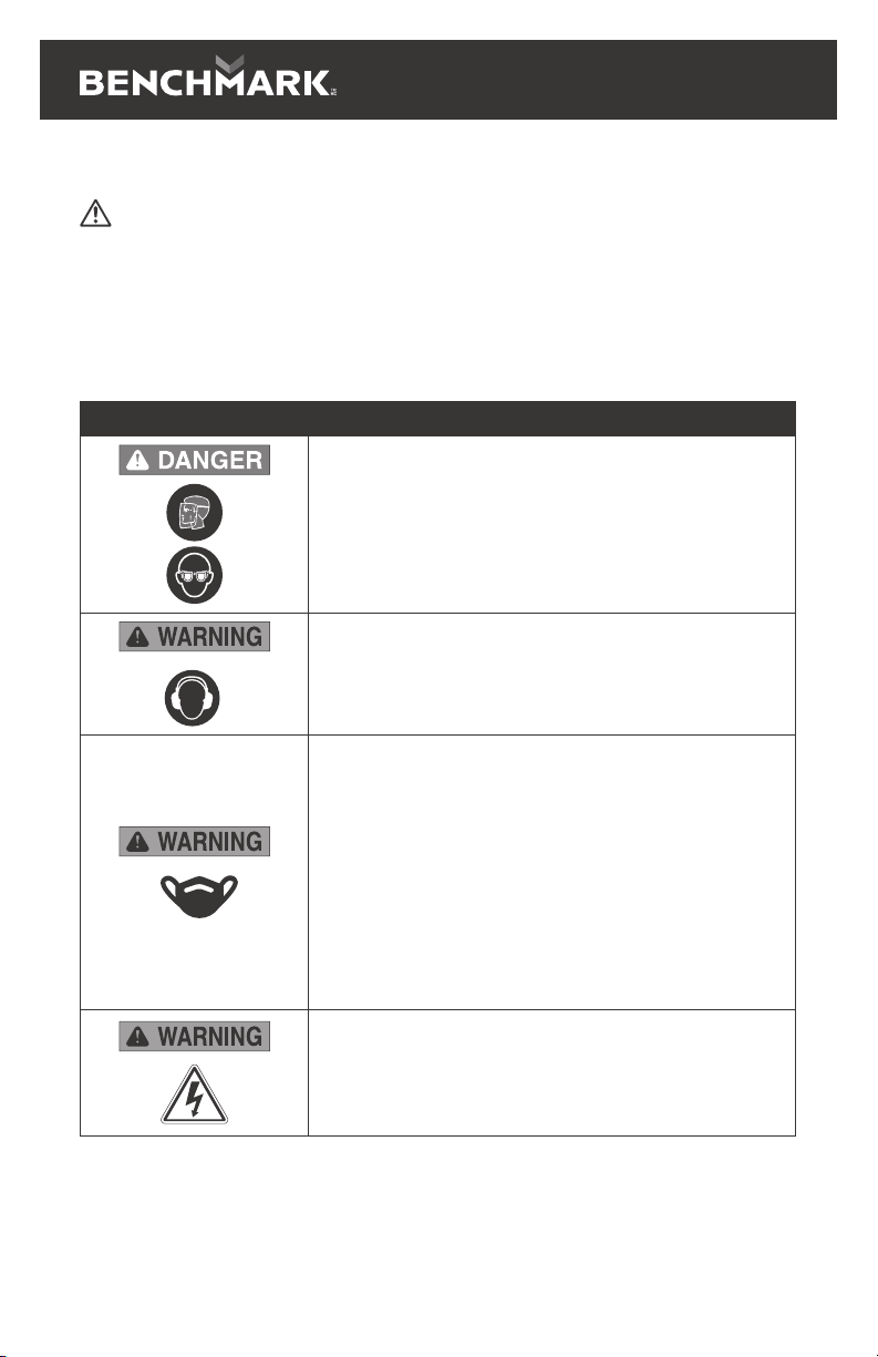
WEAR CSA APPROVED
EYE PROTECTION
WEAR EAR
PROTECTION
WEAR A
FACE MASK
READ ALL INSTRUCTIONS BEFORE FIRST USE.
KEEP THIS MANUAL FOR FUTURE REFERENCE.
KEEP AWAY FROM CHILDREN.
Maximum initial battery voltage (measured without a load)
is 20 volts. Normal voltage is 18 volts.
Includes 1 battery & 1 charger.
5 Year Limited Warranty on tool
3 Year Limited Warranty on battery and charger
COMPOUND MITRE SAW

1
PRODUCT SPECIFICATIONS
20V MAX 7-1/4" SLIDING COMPOUND MITRE SAW
No Load Speed 3600 RPM
Blade 7-1/4” (185mm) 40T carbide tipped/
Teflon coated
Arbor 5/8”
Mitre Stops 0, 15, 22.5, 31.6, 45°
Single Bevel 45°
Cross Cut Capacity 8” (203mm) at 90° - 6” (152mm) at 45°
Weight 26.5 Lbs. (12Kg)
BATTERY AND CHARGER
Battery voltage 1x20V 5 Ah Li-ion
(Maximum charged battery voltage, measured without
load, is 20V with a nominal value of 18V)
Charger Up to 150 minutes (#5350-010)
Replacement battery 5350-012
Replacement charger 5350-010
NEED ASSISTANCE?
Call us on our toll-free customer support line:
1-866-349-8665 (Monday through Friday 9am – 5pm Eastern Standard Time)
• Technical questions
• Replacement parts
• Parts missing from package

1347-001
20V MAX 7-1/4” SLIDING COMPOUND MITRE SAW
2
TABLE OF CONTENTS
Product Specifications................................................................................... 1
Table of Contents........................................................................................... 2
General Safety Warnings ................................................................................ 3-7
Specific Safety Rules ..................................................................................... 8-12
Symbols....................................................................................................... 13
Know Your Mitre Saw ................................................................................... 14
Assembly and Operating ............................................................................. 15-20
Maintenance ............................................................................................... 21
Exploded View ............................................................................................. 22
Part List....................................................................................................... 23-27
Warranty...................................................................................................... 27
3
GENERAL SAFETY WARNINGS
WARNING:
Before using this tool or any of its accessories, read this manual and follow all Safety
Rules and Operating Instructions. The important precautions, safeguards and
instructions appearing in this manual are not meant to cover all possible situations.
It must be understood that common sense and caution are factors which cannot be
built into the product.
EYE, EAR & LUNG PROTECTION
SYMBOL MEANING
ALWAYS WEAR EYE PROTECTION THAT CONFORMS WITH CSA
Z94.3 or ANSI SAFETY STANDARD Z87.1
FLYING DEBRIS can cause permanent eye damage. Prescription
eyeglasses ARE NOT a replacement for proper eye protection.
Non-compliant eyewear can cause serious injury if broken during
the operation of a power tool.
Use hearing protection, particularly during extended periods of
operation of the tool, or if the operation is noisy.
WEAR A DUST MASK THAT IS DESIGNED TO BE USED WHEN
OPERATING A POWER TOOL IN A DUSTY ENVIRONMENT.
Dust that is created by power sanding, sawing, grinding, drilling, and
other construction activities may contain chemicals that are known
to cause cancer, birth defects, or other genetic abnormalities. These
chemicals include:
• Lead from lead-based paints
• Crystalline silica from bricks, cement, and other masonry products
• Arsenic and chromium from chemically treated lumber.
The level of risk from exposure to these chemicals varies, according to
how often this type of work is performed. In order to reduce exposure
to these chemicals, work in a well-ventilated area, and use approved
safety equipment, such as a dust mask that is specifically designed to
filter out microscopic particles.
To avoid electrical hazards, fire hazards or damage to the tool,
use proper circuit protection.
This tool is wired at the factory for 120 Volts AC operation. It must be
connected to a 120 Volts AC, 15 Amps circuit that is protected by a
time-delayed fuse or circuit breaker. To avoid shock or fire, replace
power cord immediately if it is worn, cut or damaged in any way.

1347-001
20V MAX 7-1/4” SLIDING COMPOUND MITRE SAW
4
GENERAL SAFETY RULES
WARNING: Read all safety warnings and all instructions. Failure to follow the
warnings and instructions may result in electric shock, fire and/or serious injury.
Save all warnings and instructions for future reference.
WORK AREA SAFETY
Keep work area clean and well lit. Cluttered or dark areas invite accidents.
Do not operate power tools in explosive atmospheres, such as in the presence
of flammable liquids, gases or dust. Power tools create sparks which may ignite
the dust or fumes.
Keep children and bystanders away while operating a power tool. Distractions can
cause you to lose control.
ELECTRICAL SAFETY
Power tool plugs must match the outlet. Never modify the plug in any way.
Do not use any adapter plugs with earthed (grounded) power tools. Unmodified
plugs and matching outlets will reduce risk of electric shock.
Avoid body contact with earthed or grounded surfaces such as pipes, radiators,
ranges and refrigerators. There is an increased risk of electric shock if your body
is earthed or grounded.
Do not expose power tools to rain or wet conditions. Water entering a power tool
will increase the risk of electric shock.
Do not abuse the cord. Never use the cord for carrying, pulling or unplugging
the power tool. Keep cord away from heat, oil, sharp edges or moving parts.
Damaged or entangled cords increase the risk of electric shock.
When operating a power tool outdoors, use an extension cord suitable
for outdoor use. Use of a cord suitable for outdoor use reduces the risk of
electric shock.
If operating a power tool in a damp location is unavoidable, use a residual
current device (RCD) protected supply. Use of a ground fault circuit interrupter
(GFCI) protected supply. Use of a ground fault circuit interrupter (GFCI) reduces
the risk of electric shock.
PERSONAL SAFETY
Stay alert, watch what you are doing and use common sense when operating
a power tool. Do not use a power tool while you are tired or under the influence
of drugs, alcohol, or medication. A moment of inattention while operating power
tools may result in serious personal injury.
Use personal protective equipment. Always wear eye protection. Protective
equipment such as dust mask, non-skid safety shoes, hard hat, or hearing
protection used for appropriate conditions will reduce personal injuries.
connecting to power source and/or battery pack, picking up or carrying the
tool. Carrying power tools with your finger on the switch or energizing power tools
that have the switch on invites accidents.

5
Remove any adjusting key or wrench before turning the power tool on.
A wrench or a key left attached to a rotating part of the power tool may result
in personal injury.
Do not overreach. Keep proper footing and balance at all times. This enables
better control of the power tool in unexpected situations.
Dress properly. Do not wear loose clothing or jewellery. Keep your hair, clothing,
and gloves away from moving parts. Loose clothes, jewellery or long hair can be
caught in moving parts.
If devices are provided for the connection of dust extraction and collection
facilities, ensure these are connected and properly used. Use of dust collection
can reduce dust-related hazards.
POWER TOOL USE AND CARE
Do not force the power tool. Use the correct power tool for your application.
The correct power tool will do the job better and safer at the rate for which
it was designed.
Any power
tool that cannot be controlled with the switch is dangerous and must be repaired.
Disconnect the plug from the power source and/or the battery pack from the
power tool before making any adjustments, changing accessories, or storing
power tools. Such preventive safety measures reduce the risk of starting the
power tool accidentally.
Store idle power tools out of the reach of children and do not allow persons
unfamiliar with the power tool or these instructions to operate the power tool.
Power tools are dangerous in the hands of untrained users.
Maintain power tools. Check for misalignment or binding of moving parts,
operation. If damaged, have the power tool repaired before use.
Many accidents are caused by poorly maintained power tools.
Keep cutting tools sharp and clean. Properly maintained cutting tools with sharp
cutting edges are less likely to bind and are easier to control.
Use the power tool, accessories, and tool bits etc. in accordance with these
instructions, taking into account the working conditions and the work to be
performed.
could result in a hazardous situation.
Hold power tools by insulated gripping surfaces when performing an operation
where cutting tool may contact hidden wiring or its own cord. Contact with a
“live” wire will make exposed metal parts of the tool “live” and shock the operator.
Hold power tool by insulated gripping surfaces, when performing an operation
where the fastener may contact hidden wiring or its own cord. Fasteners
contacting a "live" wire may make exposed metal parts of the power tool “live”
and could give the operator an electric shock.

1347-001
20V MAX 7-1/4” SLIDING COMPOUND MITRE SAW
6
BATTERY TOOL USE AND CARE
Recharge only with the charger specified by the manufacturer. A charger
that is suitable for one type of battery pack may create a risk of fire when used
with another battery pack.
Use power tools only with specifically designated battery packs.
Use of any other battery packs may create a risk of injury and fire.
When battery pack is not in use, keep it away from other metal objects, like
paper clips, coins, keys, nails, screws, or other small metal objects that can
make a connection from one terminal to another. Shorting the battery terminals
together may cause burns or a fire.
Under abusive conditions, liquid may be ejected from the battery; avoid
contact. If contact accidentally occurs, flush with water. If liquid contacts
eyes, additionally seek medical help. Liquid ejected from the battery may
cause irritation or burns.
SERVICE
Have your power tool serviced by a qualified repair person using only identical
replacement parts. This will ensure that the safety of the power tool is maintained.

7
BATTERY & CHARGER SAFETY
WARNING: Only use the diagnostic charger supplied with this kit to charge
the 20V Li-ion battery. Charging any other batteries may damage the charger
and possibly cause serious injury.
Do not store or carry the battery in a manner in which metal objects could contact
the exposed metal end. Do not place the battery in aprons, pockets, drawers, etc.
with loose nails, screws, keys etc. The battery could short circuit causing a fire,
personal injury or damage to the battery. Store in a warm dry place.
Never attempt to open the battery for any reason. If the housing of the battery
breaks or cracks, immediately discontinue use and do not recharge.
Do not charge the battery if it is wet or shows any evidence of corrosion.
A small leakage from the battery may occur under extreme usage, charging or
temperature conditions. This does not indicate a failure. However, if the outer
seal is broken and this leakage gets on your skin, follow these steps:
1. Wash immediately with soap and water.
2. Neutralize with a mild acid such as lemon juice or vinegar.
3. If liquid gets into your eyes, flush immediately with clean water for a
minimum of 10 minutes and seek medical attention.
NOTE: The battery liquid is slightly acidic.
Do not incinerate the battery. It can explode in a fire.
Do not use an extension cord. Plug the charger cord directly into an electrical outlet.
Use the charger only in a standard 120V, 60 Hz electrical outlet.
BATTERY PACK RECYCLING
To preserve our natural resources, please recycle or dispose
of batteries properly. The batteries charged by this charger
may contain chemicals and metals that are harmful to the
environment. Never dispose of rechargeable batteries in your
normal household garbage or in landfill sites as they will add to the
pollution of the environment.

1347-001
20V MAX 7-1/4” SLIDING COMPOUND MITRE SAW
8
SPECIFIC SAFETY RULES
WARNING: Know your mitre saw. Do not use the mitre saw until you have
read and understand this Instruction Manual. Learn the tool’s applications and
limitations, as well as the specific potential hazards related to this tool. Following
this rule will reduce the risk of electric shock, fire, or serious injury.
Always wear eye protection. Any power tool can throw foreign objects
into your eyes and cause permanent eye damage. ALWAYS wear
safety goggles (not glasses) that comply with ANSI safety standard
Z87.1. Everyday glasses have only impact resistant lenses.
They ARE NOT safety glasses.
WARNING: Glasses or goggles not in compliance with ANSI Z87.1
could cause serious injury when they break.
Miter saws are intended to cut wood or wood-like products, they cannot be used
etc. Abrasive dust causes moving parts such as the lower guard to jam. Sparks from
• Use clamps to support the workpiece whenever possible. If supporting the
workpiece by hand, you must always keep your hand at least 100 mm from
either side of the saw blade. Do not use this saw to cut pieces that are too small
to be securely clamped or held by hand. If your hand is placed too close to the
• The workpiece must be stationary and clamped or held against both the fence
and the table. Do not feed the workpiece into the blade or cut “freehand” in
any way. Unrestrained or moving workpieces could be thrown at high speeds,
• Push the saw through the workpiece. Do not pull the saw through the workpiece.
To make a cut, raise the saw head and pull it out over the workpiece without
cutting, start the motor, press the saw head down and push the saw through
the workpiece. Cutting on the pull stroke is likely to cause the saw blade to
climb on top of the workpiece and violently throw the blade assembly towards
• Never cross your hand over the intended line of cutting either in front or
behind the saw blade. Supporting the workpiece “cross handed” i.e., holding
the workpiece to the right of the saw blade with your left hand or vice versa is
• Do not reach behind the fence with either hand closer than 100 mm from either
side of the saw blade, to remove wood scraps, or for any other reason while the
blade is spinning. The proximity of the spinning saw blade to your hand may not
• Inspect your workpiece before cutting. If the workpiece is bowed or warped,
clamp it with the outside bowed face toward the fence. Always make certain
that there is no gap between the workpiece, fence, and table along the line of
the cut. Bent or warped workpieces can twist or shift and may cause binding on
the spinning saw blade while cutting. There should be no nails or foreign objects

9
• Do not use the saw until the table is clear of all tools, wood scraps, etc., except
for the workpiece. Small debris or loose pieces of wood or other objects that
• Cut only one workpiece at a time. Stacked multiple workpieces cannot be
• Ensure the miter saw is mounted or placed on a level, firm work surface
before use. A level and firm work surface reduces the risk of the miter saw
• Plan your work. Every time you change the bevel or miter angle setting, make
sure the fence will not interfere with the blade or the guarding system. Without
turning the tool “ON” and with no workpiece on the table, move the saw blade
through a complete simulated cut to assure there will be no interference or
• Provide adequate support such as table extensions, sawhorses, etc. for a
workpiece that is wider or longer than the tabletop. Workpieces longer or wider
• Do not use another person as a substitute for a table extension or as additional
support. Unstable support for the workpiece can cause the blade to bind or the
workpiece to shift during the cutting operation pulling you and the helper into
•
• Always use a clamp or a fixture designed to properly support round material
such as rods or tubing. Rods have a tendency to roll while being cut, causing the
• Let the blade reach full speed before contacting the workpiece. This will reduce
•
moving parts to stop and disconnect the plug from the power source and/or
remove the battery pack. Then work to free the jammed material. Continued
sawing with a jammed workpiece could cause loss of control or damage to the
• After finishing the cut, release the switch, hold the saw head down and wait for
• Hold the handle firmly when making an incomplete cut or when releasing the
switch before the saw head is completely in the down position. The braking
action of the saw may cause the saw head to be suddenly pulled downward,

1347-001
20V MAX 7-1/4” SLIDING COMPOUND MITRE SAW
10
WARNING: Do not insert the battery into the unit until complete instructions
• NEVER PLACE HANDS CLOSER THAN 4" (100 mm) FROM THE BLADE.
• DO NOT OPERATE THIS MACHINE until it is completely assembled and installed
according to the instructions. A machine incorrectly assembled can cause
• OBTAIN ADVICE from a qualified person if you are not thoroughly familiar with
• MAKE CERTAIN the blade rotates in the correct direction. The teeth on the
• TIGHTEN ALL CLAMP HANDLES, knobs, and levers prior to operation. Loose
• BE SURE all blade and blade clamps are clean, recessed sides of blade clamps
are against blade and arbor screw is tightened securely. Loose or improper
• DO NOT WEDGE ANYTHING AGAINST THE FAN to hold the motor shaft.
• NEVER CUT METALS or masonry. Either of these can cause the carbide tips to
• NEVER HAVE ANY PART OF YOUR BODY IN LINE WITH THE PATH OF THE
• NEVER APPLY BLADE LUBRICANT TO A RUNNING BLADE. Applying lubricant
• DO NOT place either hand in the blade area when the saw is connected to the
• NEVER REACH AROUND OR BEHIND THE SAW BLADE. A blade can cause
• DO NOT REACH UNDERNEATH THE SAW unless the battery has been removed
• SECURE THE MACHINE TO A STABLE SUPPORTING SURFACE. Vibration can
• USE ONLY BLADES OF THE CORRECT SIZE AND TYPE specified for this tool to
• INSPECT BLADE FOR CRACKS or other damage prior to operation. A cracked
or damaged blade can come apart and pieces can be thrown at high speeds,
• CLEAN THE BLADE AND BLADE CLAMPS prior to operation. Cleaning the blade
and blade clamps allows you to check for any damage to the blade or blade
clamps. A cracked or damaged blade or blade clamp can come apart and pieces

11
• DO NOT USE WARPED BLADES. Check to see if the blade runs true and is free
from vibration. A vibrating blade can cause damage to the machine and/or
• DO NOT use lubricants or cleaners (particularly spray or aerosol) in the vicinity
of the plastic guard. The polycarbonate material used in the guard is subject to
•
• ALWAYS USE THE KERF PLATE AND REPLACE THIS PLATE WHEN DAMAGED.
Small chip accumulation under the saw may interfere with the saw blade or may
• USE ONLY BLADE CLAMPS SPECIFIED FOR THIS TOOL to prevent damage to
• CLEAN THE MOTOR AIR SLOTS of chips and sawdust. Clogged motor air slots
can cause the machine to overheat, damaging the machine and possibly causing
• NEVER LOCK THE SWITCH IN THE “ON” POSITION. Severe personal injury
• NEVER STAND ON TOOL. Serious injury could occur if the tool is tipped or if the
WARNING: Cutting plastics, sap coated wood, and other materials may cause
melted material to accumulate on the blade tips and the body of the saw blade,
WARNING: ALWAYS use safety glasses. Everyday eyeglasses are NOT
safety glasses. Also use face or dust mask if cutting operation is dusty. ALWAYS
CSA Z94.3), • ANSI S12.6 (S3.19) hearing protection, • NIOSH/OSHA/MSHA
WARNING: Some dust created by power sanding, sawing, grinding, drilling, and
other construction activities contains chemicals known to the State of California to
cause cancer, birth defects or other reproductive harm. Some examples of these
cement and other masonry products, and • arsenic and chromium from chemically
you do this type of work. To reduce your exposure to these chemicals: work in a
well-ventilated area, and work with approved safety equipment, such as those dust
• Avoid prolonged contact with dust from power sanding, sawing, grinding, drilling,
and other construction activities. Wear protective clothing and wash exposed
areas with soap and water. Allowing dust to get into your mouth, eyes, or lay on

1347-001
20V MAX 7-1/4” SLIDING COMPOUND MITRE SAW
12
WARNING: Use of this tool can generate and/or disperse dust, which may
cause serious and permanent respiratory or other injury. Always use NIOSH/
OSHA approved respiratory protection appropriate for the dust exposure. Direct
protection that conforms to ANSI S12.6 (S3.19) during use. Under some conditions
CAUTION: When not in use, place tool on its side on a stable surface where it will
not cause a tripping or falling hazard. Some tools with large battery packs will stand
• When replacing the blade, make sure the replacement blade is 7 1/4" in
diameter and is rated for at least 3600 RPM. Installing an incorrect blade will
result in possible injury and poor cutting action.
• After changing a blade or making adjustments make sure the blade clamp
screw is securely tightened. Loose blades and adjustment devices will be
violently thrown.
• Never touch the blade during or immediately after use. After use, the blade is too
hot to be safely touched with bare hands.

13
SYMBOLS
WARNING: Some of the following symbols may appear on the mitre saw. Study
these symbols and learn their meaning. Proper interpretation of these symbols will
V Volts n
~
Three-phase alternating
current with neutral
A Amperes Read all documentation
Hz Hertz Direct current
W Watts noNo load speed
kW Kilowatts Alternating or direct current
Microfarads Class II Construction
L Litres Splash-proof construction
kg Kilograms Watertight construction
H Hours Protective grounding at
terminal, Class I tools
N/cm² Newtons per square
centimetre .../min Revolutions or reciprocations
per minute
Pa Pascals Diameter
OPM Oscillation per minute 0
Min Minutes Directional Arrow
SSeconds Warning symbol
~or AC Alternating current Wear eye protection
~
Three-phase
alternating current
This symbol designates that this tool os listed with U.S. repuirements by
MET Laboratories, Inc.
UL 62841-1, UL 62841-3-9
CAN/CSA-C22.2 No. 62841-1, CAN/CSA-C22.2 No. 62841-3-9.

1347-001
20V MAX 7-1/4” SLIDING COMPOUND MITRE SAW
14
KNOW YOUR 20V MAX 7 1/4” SLIDING
COMPOUND MITRE SAW
1. Build in LED
2. LED ON/OFF switch
3. Saw arm
4. Release knob
5. Operating handle
6. Upper fixed blade guard
7. G clamp
8. Rotating blade guard
9. Guard retraction arm
10. Blade bolt cover
11. Dust bag
12. Bevel lock
13. Bevel scale
14. Fence
15. 6mm hex key
16. Mitre table
17. Mitre scale
18. Table insert
19. Trigger switch
20. Mitre lock knob
21. Mitre latch
22. Spindle lock
23. Slide bars
24. Slide lock
25. Trenching depth adjustment screw
26. Trenching stop
27. Trenching depth lock nut
28. 45°bevel adjustment screw
29. 0°bevel adjustment screw
30. Release latch
31. Side support bars (x2)
32. Battery pack
33. Battery lock
34. Switch lock
35. Fence
36. Charger
36 32
15
ASSEMBLY AND OPERATING
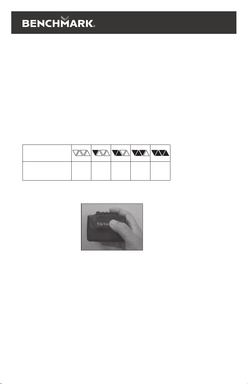
CHECKING THE BATTERY CHARGER STATUS
The level of charge remaining in the battery can be checked by using the battery
LED power indicator that is contained on the end of the battery.
NOTE: The battery charge remaining may be checked while the battery is installed
in the tool with the ON/OFF switch turned OFF. It may also be checked while the
battery is removed from the tool. DO NOT check the battery charge remaining while
the battery is in the charger. You will get a false reading and you may also damage
the battery status system.
1. Press and hold the battery status button located on the end of the battery.
2. One or more of the Four LED lights in the LED window will come ON to indicate
the amount of charge that is remaining in the battery as follows:
3. Release the battery status button to turn the LEDs OFF.
CHARGING THE BATTERY PACK
1. Place the battery charger (1) in a dry location near a 110–120V 60 Hz
2. Plug the battery charger into the outlet and make sure the green LED
indicator light (5) comes ON. If it does not, refer to the chart (Fig. 2)
to identify the problem.
3. Turn the battery (2) upside down and slide it onto the charger.
NOTE: Make sure the grooves (3) in the sides of the battery slide over the
matching tabs on the charger (4) until the battery latch “clicks” into place.
Charge Level
Indicator
Amount of Charge
Remaining
0 -
10%
10 -
25%
25 -
50%
50 -
75%
75 -
100%

1347-001
20V MAX 7-1/4” SLIDING COMPOUND MITRE SAW
16
NOTES:
1. When the charger is plugged into the wall receptacle and NO battery
is on the charger, the green indicator light (5) will turn ON indicating the
charger is “live”.
2. When a discharged battery is installed on the charger, the green indicator light
will turn OFF and the red indicator light (6) will turn ON. The red indicator light
indicates the battery is being charged.
3. If the red indicator light does not come ON, check to make sure battery pack
is slid fully onto the charger and the electrical outlet is working properly.
4. See Fig. 3 below for other indicator light functions.
5. A discharged battery pack should be fully charged in approximately 2.5 hrs.
6. It is normal for the battery charger to hum and be warm to the touch
during operation.
7. If the battery pack does not charge properly, check to make sure the electrical
outlet is “live”.
8. Do NOT charge batteries when the work area or the battery temperature
is at or below 5°C / 41°F or above 40.5°C / 105°F.
GREEN
LIGHT
RED
LIGHT
BATTERY
INSERTED
INTO CHARGER
CHARGING STATUS
ON OFF NO Charger connected
to power supply
OFF Blink YES Battery being
charged
ON OFF YES Battery fully charged
OFF ON YES Battery is charged
but not operational
on tool. This may
indicate defective /
bad contact
on battery.
ON ON YES Charging conditions
are either too hot
or too cold
Fig. 1 Fig. 2

17
TRANSPORTATION
Lift the mitre saw only when the saw arm is locked in the down position, the saw is
Only lift the saw by the operating handle (5) or outer castings. Do not lift the saw
using the guards.
BENCH MOUNTING
The saw base has holes in each corner to facilitate bench mounting.
1. Place the saw on a level, horizontal bench or worktable using bolts (not supplied)
and fix the saw to the bench using 4 bolts.
2. If desired, you can mount the saw to a piece of 1/2” (13 mm) or thicker plywood
which can then be clamped to your work support or moved to other job sites and
re-clamped.
CAUTION. Make sure that the mounting surface is not warped as an uneven
surface can cause binding and inaccurate sawing.
RELEASE KNOB
The release knob (4) is provided for holding the cutting head down while
transporting or storing the mitre saw. The saw must never be used with the release
knob locking the head down.
MITRE TABLE LOCKS
The mitre table locks (20) are used to lock the table at the desired mitre angle.
The mitre saw cuts from 0° to 45°. To adjust the mitre angle loosen the mitre table
locks (20 & 21) and rotate the mitre table to the desired position. The mitre table
features positive click stops at 0°, 15°, 22.5°, 30° and 45° for quick setting of
common mitre angles.
BEVEL LOCK
The bevel lock (12) is used to set the blade at the desired bevel angle. The mitre saw
bevel cuts from 0° to 45° to the left. To adjust the bevel angle loosen the bevel lock
and adjust the saw arm to the desired bevel angle.
SPINDLE LOCK BUTTON
The spindle lock button (22) prevents the blade in the saw from rotating. Depress
and hold the spindle lock button while installing, changing, or removing the blade.
ROTATING LOWER BLADE GUARD
The rotating lower blade guard (8) provides protection from both sides of the blade.
It retracts over the upper blade guard (6) as the saw is lowered into the workpiece.

1347-001
20V MAX 7-1/4” SLIDING COMPOUND MITRE SAW
18
TURNING ON AND OFF
1.
trigger switch (19).
2.
DUST EXTRACTION
1. Fit the dust bag (11) to the dust extraction port.
2. A vacuum dust extraction device can be connected to the dust extraction port.
Use a suitable vacuum adaptor if necessary. The dust extraction port has an
internal diameter of 1-1/2”.
SETTING THE TABLE SQUARE WITH THE BLADE
1. Make sure that the battery is removed from the power point.
2. Push the saw arm (3) down to its lowest position and engage the release
knob (4) to hold the saw arm in the transport position.
3. Loosen the mitre locks (20) and lift the mitre latch (21).
4. Rotate the table (16) until the pointer is positioned at 0°.
5. Release mitre latch (21) and tighten the mitre locks (20).
6. Loosen the bevel lock (12) and set the saw arm (3) at 0°bevel (the blade at 90°
to the mitre table). Tighten the bevel lock (12).
7. Place a set square against the table (16) and the flat part of the blade.
8. Rotate the blade by hand and check the blade-to-table alignment at
several points.
9. The edge of the set square and the saw blade should be parallel.
10.If the saw blade angles away from the set square, adjust as follows.
11.Use a 10 mm wrench or adjustable wrench to loosen the lock nut securing
the 0° bevel adjustment screw (29). Also, loosen the bevel lock (12).
12.Adjust the 0° bevel adjustment screw (29) using a 4 mm hex key to bring
the saw blade into alignment with the square.
13.Loosen the Phillips head screw holding the pointer of the bevel scale (13)
and adjust the position of the pointer so that it accurately indicates zero on
the scale. Retighten the screw.
14.Retighten the bevel lock (12) and the lock nut securing the 0° bevel
adjustment screw (29).

19
SETTING THE FENCE SQUARE WITH THE TABLE
1. Make sure that the battery is removed from the saw.
2. Push the saw arm (3) down to its lowest position and engage the release
knob (4) to hold the saw arm in the transport position.
3. Loosen the mitre locks (20) and lift the latch (21).
4. Rotate the table (16) until the pointer is positioned at 0°.
5. Release mitre latch (21) and tighten the mitre locks.
6. Using a 5 mm hex key, loosen the two screws securing the fence
(14) to the base.
7. Place a square against the fence (14) and alongside the blade.
8. Adjust the fence (14) until it is square with the blade.
9. Tighten the screws securing the fence (14).
10.Loosen the Phillips head screw holding the pointer of the mitre scale (17) and
adjust it so that it accurately indicates the zero position on the mitre scale.
11.Retighten the screw securing the mitre scale pointer.
CHANGING A BLADE
1. Make sure that the battery is removed from the power point.
2. Push down on the operating handle (5) and pull the release knob (4) to
disengage the saw arm (3).
3. Raise the saw arm (3) to its highest position.
4. Loosen the cover plate screw about 2 turns with a Phillips screwdriver.
Do not remove this screw from the tool.
5. Pull the rotating blade guard (8) down. When the rotating blade guard (8)
is positioned over the upper fixed blade guard (6) it is possible to access
the blade bolt.
6. Lift and hold up the lower blade guard (8) to expose the threaded blade bolt.
7. Hold the rotating guard (8) up and press the spindle lock button (22).
Rotate the blade until the spindle locks.
8. Use the 6 mm hex key provided to loosen and remove the blade bolt.
(Loosen in a clockwise direction as the blade screw has a left-hand thread).
9. Remove the flat washer, outer blade washer and the blade.
10.Wipe a drop of oil onto the inner blade washer and the outer blade washer where
they contact the blade.
11.Fit the new blade onto the spindle taking care that the inner blade washer sits
behind the blade.
12.Replace the outer blade washer.
13.Depress the spindle lock button and replace the flat washer and blade bolt.
14. Use the 6 mm hex key to tighten the blade bolt securely (tighten in an anti-
clockwise direction).
Table of contents
Other Benchmark Saw manuals

Benchmark
Benchmark 1265-002 User manual

Benchmark
Benchmark 1265-001 User manual

Benchmark
Benchmark 1270-204 User manual

Benchmark
Benchmark 1345-300 User manual

Benchmark
Benchmark 1347-006 User manual

Benchmark
Benchmark 1270-205 User manual

Benchmark
Benchmark 1347-100 User manual

Benchmark
Benchmark 1265-000 User manual

Benchmark
Benchmark 1270-001 User manual

Benchmark
Benchmark 1347-005 User manual


