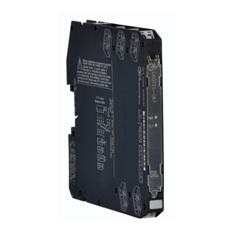
Bender DI-1PSM User manual

Handbuch/Manual
1
DE EN
RS-485 interface repeater
Intended use
The RS-485 interface repeater DI-1PSM is designed for signal am-
plification on the RS-485 interface (external BMS bus*, Modbus
RTU). This is required when the network distance exceeds a
length of 1200 m or when the maximum permissible number of
bus nodes is exceeded.
Application
•Extension of the maximum possible bus length by 1200 m
in BMS systems (EDS, RCMS, MEDICS® systems)
•Extension of the maximum possible bus nodes by 31*
•Protection against spikes by galvanic separation between
the input and output circuit and the power supply
•Implementation of resonant stubs (refer to BMS manual)
Device features
•Plastic enclosure for DIN rail mounting
•Adjustable baud rate
•Galvanic separation between the input and output circuit
and the power supply
•Supply voltage AC/DC 24 V ± 20 %
* depending on used transceivers.
Safety information
Also refer to the manual "BMS bus" and accompanying documen-
tation.
Installation and connection
Use on the internal BMS bus is not recommended
due to manual baud rate setting. For this applica-
tion, type DI-1DL is available.
This manual is intended for qualified personnel
working in electrical engineering and electronics!
In addition to this manual, the documentation of
the device includes a sheet entitled "Important safe-
ty instructions for Bender products".
Risk of fatal injury from electric shock!
Any work on electrical installations which is not car-
ried out properly can lead to death and injury!
Only skilled persons are permitted to carry out the
work necessary to install, commission and run a de-
vice or system.
Risk of fatal injury from electric shock!
Prior to installation and before work activities are
carried out on the connecting cables, make sure
that the mains power is disconnected.
Failure to comply with this safety information
may cause electric shock to personnel. Further-
more, substantial damage to the electrical instal-
lation and destruction of the device can occur.
DANGER
DANGER
RS-485-Schnittstellenverstärker
Bestimmungsgemäße Verwendung
Der RS-485-Schnittstellenverstärker DI-1PSM wird zur Verstär-
kung von Signalen auf der RS-485-Schnittstelle (externer BMS-
Bus*, Modbus RTU) eingesetzt. Dies ist dann notwendig, wenn
die Busleitung eine Länge von 1200 m überschreitet oder die ma-
ximal zulässige Anzahl an Busteilnehmern überschritten ist.
Applikation
• Verlängerung der max. zulässigen Busleitung um jeweils
1200 m in BMS-Systemen (EDS-, RCMS-, MEDICS®-Systeme)
• Erhöhung der max. möglichen Busteilnehmer um 31*
• Schutz vor Störspitzen durch galvanische Trennung zwi-
schen Eingangs-, Ausgangskreis und Stromversorgung
• Realisierung von Stichleitungen (siehe BMS-Handbuch)
Gerätemerkmale
• Kunststoffgehäuse für Hutprofilschiene
• Einstellbare Baudrate
• Galvanische Trennung zwischen Eingangs-, Ausgangs-
kreis und Stromversorgung
• Versorgungsspannung AC/DC 24 V ± 20 %
* je nach verwendeten Transceiver.
Sicherheitshinweise allgemein
Beachten Sie das Handbuch „BMS-Bus“ und die beiliegende
Dokumentation.
Montage und Anschluss
Einsatz am internen BMS-Bus wird aufgrund der
manuellen Baudraten-Einstellung nicht empfoh-
len. Dafür steht der Typ DI-1DL zur Verfügung.
Dieses Handbuch richtet sich an Fachpersonal der
Elektrotechnik und Elektronik! Bestandteil der Gerä-
tedokumentation sind neben diesem Handbuchdie
beiliegenden „Wichtigen sicherheits-technischen
Hinweise für Bender-Produkte“.
Lebensgefahr durch Stromschlag!
Nicht fachgerecht durchgeführte Arbeiten an elekt-
rischen Anlagen können zu Gefahren für Gesund-
heit und Leben führen! Alle erforderlichen Arbeiten
zum Einbau, zur Inbetriebnahme und zum laufen-
den Betrieb des Gerätes oder Systems sind durch ge-
eignetes Fachpersonal auszuführen.
Lebensgefahr durch Stromschlag!
Stellen Sie vor Einbau des Gerätes und vor Arbei-
ten an den Anschlüssen des Gerätes sicher, dass
die Anlage spannungsfrei ist.
Wird dies nicht beachtet, so besteht für das Perso-
nal die Gefahr eines elektrischen Schlages.
Außerdem drohen Sachschäden an der elektri-
schen Anlage und die Zerstörung des Gerätes.
GEFAHR
GEFAHR
DI-1PSM
DI-1PSM_D00180_00_M_DEEN/09.2016
DE
EN

2DI-1PSM_D00180_00_M_DEEN/09.2016
DI-1PSM
Installation
The device is suited for DIN rail mounting acc. to IEC 60715.
The tightening torque for the terminal screws is:
0.5…0.6 Nm (4.3…5.3 lb-in).
Connection
Fig. 1: Dimensions and wiring diagram, all dimensions in mm
Shielding the Data Cables
Shield the data cables using a shield terminal block that is fixed in
the terminal block. The terminal block is connected capaci-
tively (Port A) resp. firmly (Port B) to the DIN rail contact. on the
bottom side of the device.
Commissioning
1. The baud rate is to be set via the DIP switch (DIP 1…4)
according to the transmission rate in the bus system.
2. One DIP switch is available per bus segment to terminate
the bus and to generate the required bias voltage.
The termination is carried out as shown in the following example
of a BMS bus system.
Pay attention to correct polarity for connection at
BMS bus. Attention should be paid to the BMS bus
termination (see BMS manual).
Establish an electrically conductive connection
between the DIN rail and protective earth using a
grounding terminal block. so that the integrated
surge protection works and that the shielding of
the data cable is effective.
Use shielded twisted pair cables. Connect the
cable shield to both sides of the transmission path.
CAUTION
Montage
Das Gerät ist für Schnellmontage auf Hutprofilschiene nach
IEC 60715 geeignet.
Beachten Sie das Anzugsdrehmoment für die Klemmschrauben
der Anschlüsse: 0,5…0,6 Nm (4,3…5,3 lb-in).
Anschluss
Abb. 1: Maßbild und Anschlussbild, Maßbild; alle Maße in mm
Abschirmung der Datenkabel
Schirmen Sie die Datenkabel ab, indem Sie die Schirmklemme in
der -Klemme befestigen. Die -Klemme ist kapazitiv (Port A)
bzw. fest (Port B) mit dem Hutschienenkontakt auf der Geräteun-
terseite verbunden.
Inbetriebnahme
1. Über die DIP-Schalter (DIP 1…4) ist die Baudrate entspre-
chend der Übertragungsrate im Bussystem einzustellen.
2. Zur Terminierung des Busses und zur Erzeugung der erfor-
derlichen Vorspannung ist pro Bussegment ein DIP-Schal-
ter vorhanden.
Die Terminierung ist wie im folgenden Beispiel eines BMS-Bus-
Systems vorzunehmen.
Bei Anschluss an BMS-Bus auf korrekte Polung
achten! Terminierung des BMS-Busses beachten
(siehe BMS-Handbuch).
Stellen Sie eine elektrisch leitende Verbindung mit-
tels einer Erdungsklemme zwischen Hutschiene
und Schutzerde her, damit der integrierte Über-
spannungsschutz funktioniert und die Abschir-
mung der Datenleitung wirksam aufgelegt ist.
Verwenden Sie abgeschirmte twisted-pair Kabel.
Schließen Sie die Kabelschirmung auf beiden Sei-
ten der Übertragungsstrecke an.
VORSICHT
114,5
99
Tiefe/Depth 22,5
Schirm/
Shield
Schirm/
Shield
A
B
C
12 D
12
C
12
D
1
2
BB
BE
BBE
B
E
= Busteilnehmer mit Abschlusswiderstand
= Busteilnehmer ohne Abschlusswiderstand
= Bus device with terminating resistor
= Bus device without terminating resistor

3
DI-1PSM_D00180_00_M_DEEN/09.2016
DI-1PSM
* The bias voltage generation is generally activated for the BMS
bus master (via software) and deactivated for the BMS slaves.
Configuration
1. Disengage the housing cover with a screwdriver.
2. Carefully pull the PCB out of the housing as far as possible.
Transmission speed
Set the transmission speed using the DIP switches.
Termination/bias voltage
AMaster
Terminating resistor activated via switch on
device (ON)* or external terminating resistor
between terminals A and B
BSlave Terminating resistor deactivated via switch on
device (OFF)*
C
RS-485-
repeater
DI-1PSM
Bus 1: Terminating resistor and bias voltage
generation deactivated via switch on device
(DIP switch Terminate RS-485 (A): OFF)
Bus 2: Terminating resistor and bias voltage
generation activated via switch on device (DIP
switch Terminate RS-485 (B): ON)
D
RS-485-
repeater
DI-1PSM
Bus 1: Terminating resistor and bias voltage
generation deactivated via switch on device
(DIP switch Terminate RS-485 (A): OFF), external
terminating resistor between terminals D(A) and
D(B)
Bus 2: Terminating resistor and bias voltage
generation activated via switch on device (DIP
switch Terminate RS-485 (B): ON)*
ESlave
Terminating resistor activated via switch on
device (ON) or external terminating resistor bet-
ween terminals A and B
Risk of electrostatic discharge!
Static charges can damage electronic devices. Re-
move electrostatic discharge from your body be-
fore opening and configuring the device.
Set all PSM repeaters and bus devices to the same
data speed.
CAUTION
ON
OFF
ON
OFF
Terminate
Port B
Terminate
Port A
ON
* Die Vorspannungserzeugung ist beim BMS Bus Master generell
(per Software) aktiviert und bei BMS Slaves deaktiviert.
Konfiguration
1. Entriegeln Sie den Gehäusekopf mit einem Schrauben-
dreher.
2. Ziehen Sie die Leiterplatte bis zum Anschlag aus dem
Gehäuse heraus.
Übertragungsrate
Stellen Sie die Übertragungsrate mit Hilfe der DIP-Schalter ein.
Terminierung/Vorspannung
AMaster
Abschlusswiderstand über Schalter am Gerät
aktiviert (ON)* oder externer Abschlusswider-
stand zwischen den Klemmen A und B
BSlave Abschlusswiderstand über Schalter am Gerät
deaktiviert (OFF)*
C
RS-485-
Schnitt-
stellen-
verstärker
DI-1PSM
Bus 1: Abschlusswiderstand und Vorspannungs-
erzeugung über Schalter am Gerät deaktiviert
(DIP-Schalter Terminate RS-485 (A): OFF)
Bus 2: Abschlusswiderstand und Vorspannungs-
erzeugung über Schalter am Gerät aktiviert
(DIP-Schalter Terminate RS-485 (B): ON)
D
RS-485-
Schnitt-
stellen-
verstärker
DI-1PSM
Bus 1: Abschlusswiderstand und Vorspannungs-
erzeugung über Schalter am Gerät deaktiviert
(DIP-Schalter Terminate RS-485 (A): OFF), exter-
ner Abschlusswiderstand zwischen den Klem-
men D(A) und D(B)
Bus 2: Abschlusswiderstand und Vorspannungs-
erzeugung über Schalter am Gerät aktiviert
(DIP-Schalter Terminate RS-485 (B): ON)*
ESlave
Abschlusswiderstand über Schalter am Gerät
aktiviert (ON) oder externer Abschlusswider-
stand zwischen den Klemmen A und B
Vorsicht vor elektrostatischer Entladung!
Statische Aufladungen können elektronische Ge-
räte beschädigen. Entladen Sie die elektrische La-
dung Ihres Körpers vor dem Öffnen und
Konfigurieren des Gerätes.
Stellen Sie alle PSM-Repeater und Busteilnehmer
auf die gleiche Datenrate ein.
SPEED
(kbit/s)
DIP
1234
9,6 ON OFF ON ON
19,2 ON OFF ON OFF
38,4 ON OFF OFF ON
57,6 ON OFF OFF OFF
VORSICHT

4DI-1PSM_D00180_00_M_DEEN/09.2016
DI-1PSM
Alle Rechte vorbehalten. Nachdruck und Vervielfältigung nur mit
Genehmigung des Herausgebers. Änderungen vorbehalten!
©Bender GmbH & Co. KG
All rights reserved. Reprinting and duplicating only with
permission of the publisher. Subject to change!
©Bender GmbH & Co. KG
Fotos: Bender Archiv. Photos: Bender archives.
Bender GmbH & Co. KG
Londorfer Str. 65 •35305 Grünberg • Germany
Postfach 1161 •35301 Grünberg • Germany
Tel.: +49 6401 807-0 •Fax: +49 6401 807-259
BENDER Group
Technische Daten
Isolationskoordination nach IEC 60664-1
Bemessungsspannung .......................................................................................................................
Bemessungs-Stoßspannung/Verschmutzungsgrad..............................................................2 kV/3
Versorgungsspannung
Versorgungsspannung US...............................................................................siehe Bestellangaben
Stromaufnahme ............................................................................................................... ≤ 100 mA
Schnittstellen
Schnittstelle/Protokoll.....................................................................2 x RS-485 /BMS/Modbus RTU
Baudrate über DIP-Schalter einstellbar................................................................4,8…1500 kbit/s
Leitungslänge (Segmentlänge) ........................................................................................≤ 1200 m
Leitung (paarweise verdrillt, Schirm einseitig an PE) .................empfohlen: J-Y(St)Y min. 2 x 0,8
Integrierter Überspannungsschutz ................................mit Transientenableitung zur Tragschiene
Betriebsart.........................................................................................................................halbduplex
Datenrichtungsumschaltung......................................................................................selbststeuernd
Kaskadierbarkeit ............................................................................................9 (4,8…93,75 kbit/s)
Abschlusswiderstand, über DIP-Schalter wählbar.................................................................. 220Ω
Geräteadresse, BMS-Bus .................................................................................................................--
Melde-LEDs ............................................................................ ON (grün), R x D (grün), T x D (gelb)
Allgemeine Daten
EMV-Störfestigkeit............................................................................................. nach EN 61000-6-2
EMV-Störaussendung ........................................................................................... nach EN 50081-1
Klimaklassen nach IEC 60721
Ortsfester Einsatz ..........................................................................................................................3K5
Transport.......................................................................................................................................2K3
Langzeitlagerung..........................................................................................................................1K4
Arbeitstemperatur .....................................................................................................0 °C…+55 °C
Mechanische Beanspruchung nach IEC 60721
Ortsfester Einsatz ........................................................................................................................ 3M4
Transport..................................................................................................................................... 2M2
Langzeitlagerung........................................................................................................................ 1M3
Betriebsart .....................................................................................................................Dauerbetrieb
Einbaulage .............................................................................................................................beliebig
Anschlussart........................................................................................ SteckbarerSchraubanschluss
Anschlussvermögen
starr/flexibel/Leitergrößen..............................................................0,2…2,5mm2/AWG24…12
Schutzart Einbauten (IEC 60529)................................................................................................IP30
Schutzart Klemmen (IEC 60529).................................................................................................IP20
Schnellbefestigung auf Hutprofilschiene..................................................DIN EN 60715/IEC 60715
Gewicht.................................................................................................................................≤ 130 g
Bestellangaben
Typ /Type Versorgungsspannung US/ Supply voltage USArt.-Nr. / Art. No.
DI-1PSM AC/DC 24 V ± 20 % B 9501 2044
Technical data
Insulation coordination acc. to IEC 60664-1
Rated voltage......................................................................................................................................
Rated impulse voltage/pollution degree................................................................................ 2 kV/3
Supply voltage
Supply voltage US ..................................................................................... see ordering information
Current consumption ........................................................................................................≤ 100 mA
Interfaces
Interface/protocol............................................................................ 2 x RS-485 /BMS/Modbus RTU
Baud rate adjustable via DIP switch..................................................................... 4.8…1500 kbit/s
Cable length (segment length)........................................................................................ ≤ 1200 m
Cable (twisted pair, one end of shield connected to PE) ........recommended: J-Y(St)Y min. 2x0.8
Integrated surge protection ...............................................with transient discharge to the DIN rail
Operating mode ..............................................................................................................half-duplex
Change of data direction............................................................... automatic data direction control
Cascading capability...................................................................................... 9 (4.8…93.75 kbit/s)
Terminating resistor, selectable via DIP switch....................................................................... 220Ω
Device address, BMS bus.................................................................................................................--
Alarm LEDs .......................................................................ON (green), R x D (green), T x D (yellow)
General data
EMC immunity ............................................................................................... acc. to EN 61000-6-2
EMC emission ......................................................................................................acc. to EN 50081-1
Classification of climatic conditions IEC 60721
Stationary use...............................................................................................................................3K5
Transport.......................................................................................................................................2K3
Storage..........................................................................................................................................1K4
Operating temperature ............................................................................................ 0 °C…+55 °C
Classification of mechanical conditions acc. to IEC 60721
Stationary use..............................................................................................................................3M4
Transport......................................................................................................................................2M2
Storage.........................................................................................................................................1M3
Operating mode ............................................................................................. continuous operation
Mounting........................................................................................................................anyposition
Connection............................................................................................Pluggable screw connection
Connection properties
rigid/flexible/conductor sizes .........................................................0.2…2.5 mm2/AWG24…12
Degree of protection, internal components (IEC 60529) ..........................................................IP30
Degree of protection, terminals (IEC 60529).............................................................................IP 20
DIN rail mounting acc. to ...................................................................................................IEC 60715
Weight ................................................................................................................................. ≤ 130 g
Ordering details
This manual suits for next models
1
