Bender EDS460-DG User manual
Power in electrical safety
Operating Manual
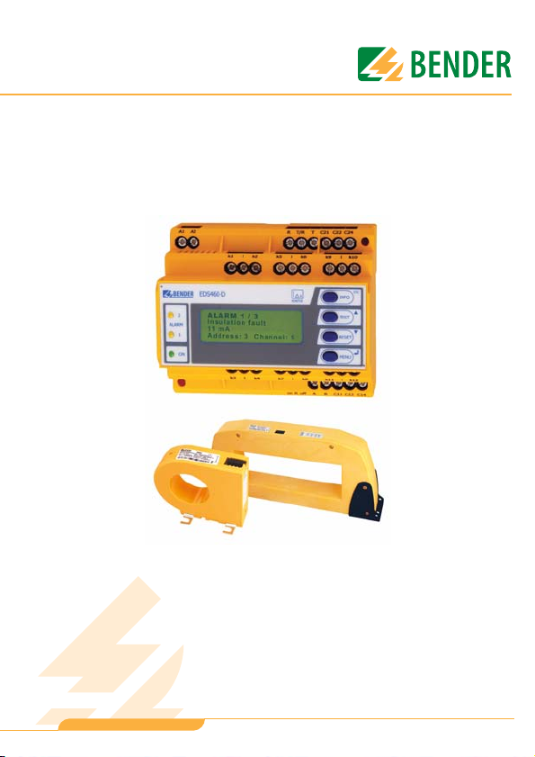
EDS460-DG
Insulation fault evaluators
Software version: D303 V1.0 / D256 V2.2
TGH1429en/10.2008

Dipl.-Ing. W. Bender GmbH & Co.KG
Londorfer Str. 65 • 35305 Grünberg • Germany
Postfach 1161 • 35301 Grünberg • Germany
Tel.: +49 (0)6401-807-0
Fax: +49 (0)6401-807-259
E-Mail: [email protected]om
Web: http://www.bender-de.com
©Dipl.-Ing. W. Bender GmbH & Co.KG
All rights reserved.
Reprinting only with permission
of the publisher.
Subject to change!

Table of Contents
3
TGH1429en/10.2008
1. How to use this operating manual effectively ........................................... 7
1.1 How to use this manual ................................................................................. 7
1.2 Explanations of symbols and notes ........................................................... 7
2. Safety information ........................................................................................... 9
2.1 Intended use ...................................................................................................... 9
2.2 Skilled persons ............................................................................................... 10
2.3 General safety information ........................................................................ 10
2.4 Delivery conditions, guarantee, warranty and liability .................... 11
3. System description ........................................................................................ 13
3.1 Properties ......................................................................................................... 13
3.1.1 Typical applications ...................................................................................... 13
3.1.2 Standards ......................................................................................................... 13
3.1.3 System versions ............................................................................................. 13
3.1.4 System features .............................................................................................. 13
3.2 Function of the EDS system ....................................................................... 14
3.2.1 Block diagram EDS system ......................................................................... 15
3.2.2 Test cycle .......................................................................................................... 16
3.2.3 Currents in the EDS system ........................................................................ 17
3.2.4 Requirements for reliable insulation fault location .......................... 18
4. Installation and connection ......................................................................... 21
4.1 Unpacking ........................................................................................................ 21
4.2 Fuses, max. voltage, cable lengths ......................................................... 21
4.3 Notes on mounting ...................................................................................... 22
4.3.1 Dimension diagram EDS460-DG .............................................................. 22
4.4 Connection ...................................................................................................... 23
4.4.1 Wiring diagram EDS460-DG ...................................................................... 23

Table of Contents
4TGH1429en/10.2008
4.4.2 Connection of W…, WR…, WS…series measuring current
transformers .................................................................................................... 25
4.4.3 Connection example EDS standard system with FTC470XET ....... 26
5. Commissioning .............................................................................................. 29
5.1 Before switching on ...................................................................................... 29
6. Operation ........................................................................................................ 31
6.1 Operating and display elements EDS460-DG ..................................... 31
6.2 Working in operating mode ...................................................................... 32
6.2.1 Standard display ............................................................................................ 32
6.2.2 Alarm messages and their effects ........................................................... 32
6.2.3 Carrying out a test ......................................................................................... 34
6.2.4 Resetting saved alarm messages (RESET) ............................................ 35
6.2.5 Displaying standard information ............................................................. 36
6.3 Operation and setting of the EDS460-DG ............................................ 36
6.3.1 Opening the main menu ............................................................................ 36
6.3.2 Menu overview diagram ............................................................................. 38
6.3.3 Main menu functions ................................................................................... 39
6.4 The main menu .............................................................................................. 40
6.4.1 Menu 1: Alarm/meas. values ..................................................................... 40
6.4.2 Menu 2: History .............................................................................................. 42
6.4.3 Menu 3: settings ............................................................................................. 43
6.4.3.1 Settings menu 1: General ................................................................... 44
6.4.3.2 Settings menu 2: Channel .................................................................. 45
6.4.3.3 Settings menu 3: Relays ...................................................................... 48
6.4.3.4 Settings menu 4: History .................................................................... 50
6.4.3.5 Settings menu 5: language ............................................................... 50
6.4.3.6 Settings menu 6: Interface ................................................................. 50
6.4.3.7 Settings menu 7: Alarm addresses ................................................. 50
6.4.3.8 Settings menu 8: Clock ....................................................................... 51
6.4.3.9 Settings menu 9: password ............................................................... 52
6.4.3.10 Settings menu 10: Factory settings ................................................ 52

Table of Contents
5
TGH1429en/10.2008
6.4.3.11 Settings menu 11: Service ................................................................. 52
6.4.4 Menu 4: Control ............................................................................................. 53
6.4.4.1 Control menu 1: TEST .......................................................................... 53
6.4.4.2 Control menu 2: RESET ....................................................................... 53
6.4.4.3 Control menu 3: Test communication .......................................... 53
6.4.5 Menu 5: External devices ............................................................................ 55
6.4.6 Menu 6: Info .................................................................................................... 56
7. Tests and service ........................................................................................... 57
7.1 Periodic verification ...................................................................................... 57
7.2 Maintenance ................................................................................................... 57
7.3 Service ............................................................................................................... 57
7.4 Trouble shooting ........................................................................................... 58
7.4.1 Display device error ...................................................................................... 58
7.4.2 Device error display (channel-related) .................................................. 59
7.4.3 CT connection fault display (channel-related) ................................... 60
7.4.4 Display "peak" ................................................................................................. 60
7.4.5 External alarm ................................................................................................. 60
8. Data .................................................................................................................. 61
8.1 Standards ......................................................................................................... 61
8.2 Certifications .................................................................................................. 61
8.3 Technical data EDS460-DG ........................................................................ 62
8.4 Response sensitivity characteristics ....................................................... 65
8.4.1 EDS460-DG characteristics ......................................................................... 67
8.5 Ordering information .................................................................................. 69


How to use this operating manual effectively
7
TGH1429en/10.2008
1. How to use this operating manual effectively
1.1 How to use this manual
This operating manual describes EDS460-DG insulation fault evaluators.
It is intended for skilled personnel in the areas of electronics and elec-
trical engineering but, in particular, for planners, installers and opera-
tors of electrical systems.
Before using the equipment, please read this operating manual, the sup-
plement entitled "Important safety instructions for BENDER products",
the "BMS bus" instruction leaflet, as well as the instruction leaflets sup-
plied with the individual system components. Please keep this docu-
mentation close at hand near the equipment.
Should you have any further questions, we would be happy to be of as-
sistance. Please contact our technical sales team. We also offer a wide
range of on-site services. Contact our Service Department for further de-
tails.
Service-Hotline: 0700-BenderHelp (Telephone and Fax)
Carl-Benz-Straße 10 • 35305 Grünberg • Germany
Tel: +49(0)64 01-807 760 • Fax: +49(0)64 01- 807 629
E-Mail: info@bender-service.com • www.bender-de.com
This manual has been compiled with great care. Nevertheless, errors
and omissions cannot be entirely excluded. The BENDER companies do
not accept any liability for injuries to persons or material damage result-
ing from errors or omissions in this manual.
1.2 Explanations of symbols and notes
The following terms and symbols are used to denote hazards and in-
structions in BENDER documentation:
How to use this operating manual effectively
8TGH1429en/10.2008
This symbol indicates an immediate risk to life and limb.
Failure to observe these warnings means that death, se-
vere bodily injury or substantial material damage will oc-
cur if the corresponding precautions are not taken.
This symbol indicates a potential risk to life and limb.
Failure to observe these warnings means that death, se-
vere bodily injury or substantial material damage may
occur if the corresponding precautions are not taken.
This symbol means a possibly hazardous situation.
Failure to observe these warnings means that slight bod-
ily injury or material damage may occur if the corre-
sponding precautions are not taken.
This symbol gives important information about the cor-
rect handling of the equipment.
Failure to comply with this information can result in
equipment malfunctioning or in its environment.
This symbol guides you to application tips and particular-
ly useful items of information. This type of information
will help you to optimise your use of the equipment.
Danger !
Warning
Caution

Safety information
9
TGH1429en/10.2008
2. Safety information
2.1 Intended use
EDS460-DG insulation fault evaluators are used to localise insulation
faults in unearthed DC power supply systems (IT systems). DC systems
of DC 20...308 V can be monitored.
An EDS system consists of EDS460-DG insulation fault evaluators and
IRDH575 A-ISOMETER® or PGH insulation fault test device. Using
measuring current transformers, EDS460-DG insulation fault evaluators
detect test current signals generated by the IRDH575 insulation moni-
toring device or by the PGH... insulation fault test device and evaluate
them.
Up to 12 measuring current transformers can be connected to one
EDS460-DG. Up to 90 EDS460-DG evaluators can be connected via a
BMS bus (RS-485 interface with BMS protocol), thereby up to 1080
measuring channels (sub-circuits) can be monitored. The scanning time
for all channels is approximately 4…10 s.
Using the IRDH575 or PGH... with a high test current may
damage sensitive loads (e.g. in control circuits) or may
accidentally activate switching operations. Therefore, it
is recommended to use a PGH... with a low test current or
to set a low test current at the IRDH575. In case of doubt,
please contact a BENDER product manager.
Caution

Safety information
10 TGH1429en/10.2008
Individual parameterisation, necessary to adjust the evaluator to the ex-
isting system and utilisation conditions, must be carried out at the place
of utilisation in order to meet the requirements laid down in the stand-
ards.
Please take note of the limits for the application area specified in the
technical data. Any other use, or use which goes beyond the foregoing,
is deemed to be use other than for the intended purpose.
Intended use also implies:
The observation of all information in this operating manual.
Compliance with test intervals.
2.2 Skilled persons
Only skilled persons may work on BENDER products. Personnel who
are familiar with the assembly, commissioning and operation of the
equipment and have undergone appropriate training are considered
qualified. Personnel must have read and understood the safety section
and warning information in this operating manual.
2.3 General safety information
BENDER equipment is designed and built in accordance with the state
of the art and accepted rules in respect of technical safety. However, the
use of such devices may introduce risks to the life and limb of the user
or third parties and/or result in damage to BENDER equipment or other
property.
Only use BENDER equipment:
– for the purpose for which it is intended;
– when it is in perfect condition as far as safety is concerned;
– in accordance with the rules and regulations on accident preven-
tion that are applicable for the place of utilisation.
Any faults which may impair safety must be eliminated immediately.

Safety information
11
TGH1429en/10.2008
Do not make any unauthorised changes and only use replacement
parts and optional accessories from or recommended by the manufac-
turer of the equipment. Failure to observe this requirement can result
in fire, electric shock and injury.
Reference plates must always be clearly legible. Replace damaged or
illegible signs immediately.
2.4 Delivery conditions, guarantee, warranty and liability
The conditions of sale and delivery set out by BENDER shall apply. Con-
ditions of sale and delivery can be obtained from BENDER in printed or
electronic format.


System description
13
TGH1429en/10.2008
3. System description
3.1 Properties
3.1.1 Typical applications
Insulation fault location in DC IT systems
Main and control circuits in industrial installations and ships
Diode-decoupled DC IT systems in power stations
3.1.2 Standards
The standard DIN VDE 0100-410:2007-06; IEC 60364-4-41: 2005-12 re-
quires for unearthed power supply systems (IT systems) that a first fault
is to be eliminated with the shortest practicable delay. EDS systems al-
low fast localisation of insulation faults.
3.1.3 System versions
Insulation fault evaluators EDS460-DG-1 and EDS460-DG-2 differ in
their supply voltage.
3.1.4 System features
Universal system concept;
Modular design, hence easily adaptable to the individual conditions of
the system;
Measuring current transformers in various sizes and types of construc-
tion;
Communication between the components via BMS bus (two-wire);
All measuring current transformers are scanned simultaneously;
Central indication of faulty subcircuits;
Various setting options allow individual adjustments;
Connection to higher level control and visualisation systems can easily
be established.

System description
14 TGH1429en/10.2008
3.2 Function of the EDS system
When an insulation fault is detected by the insulation monitoring device
in the IT system, the insulation fault location process will be started.
On the occurrence of a first insulation fault, a fault current essentially
determined by the system leakage capacitances flows in the IT system.
The fundamental idea in fault location is therefore to close the fault cur-
rent loop for a short period via a defined resistance. As a result of this
principle, the system voltage itself drives a test current containing a sig-
nal that can be evaluated.
The test current signals are generated periodically by the IRDH575 re-
spectively the PGH... . The test current is limited in amplitude and time.
As this happens, the system conductors are connected alternately to
earth via a defined resistance. The test current generated in this manner
depends on the size of the present insulation fault and the system volt-
age. It is limited according to the setting of the IRDH575 respectively
the PGH... . For planning purposes, it should be noted that no system
components are present in which this test current can bring about a
damaging reaction, even in unfavourable cases.
The test current pulse flows from the test device via the live parts, taking
the shortest path to the location of the insulation fault. From there, it
flows via the insulation fault and the PE back to the IRDH575 respec-
tively PGH... . This test current pulse is then detected by the measuring
current transformers located in the insulation fault path, and is signalled
by the connected insulation fault evaluator.

System description
15
TGH1429en/10.2008
3.2.1 Block diagram EDS system
Key:
EDS... Insulation fault evaluator
PGH... Insulation fault test device
IRDH575
A-ISOMETER® IRDH575 with integrated test current generator
UsCurrent source IT system
W Measuring current transformers
V Electrical load
RFInsulation fault
PE
Protective conductor resp. equipotential bonding conductor
BMS BMS bus
USV
IT-System
W...
EDS...
IRDH575/
PGH...
PE
RF
L (L-)
L1(L+)
3
1
BMS
System description
16 TGH1429en/10.2008
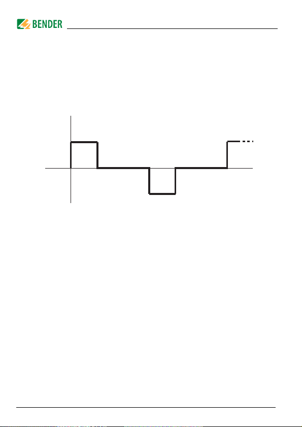
3.2.2 Test cycle
The duration of a test current pulse cycle is 6 seconds. The IRDH575 or
PGH... alternatively sends positive or negative test current pulses. The
test cycle of the IRDH575 or PGH... is shown in different switch posi-
tions (1,2,3) in the block diagram below, ("Block diagram EDS system"
on page 15).
EDS start
Position
PGH... 1331
sec 4 sec sec 4 sec

System description
17
TGH1429en/10.2008
3.2.3 Currents in the EDS system
In addition to the block diagram on page 15, the path of the residual
currents and the test current is shown in the diagram below:
Key:
............. Test current loop I(ds)
.. .. .. ..
Residual currents I(d) (example) may be caused by converters.
CE-V Upstream capacitances, system leakage capacitances
upstream the measuring current transformer.
CE-N Downstream capacitances, system leakage capacitances
downstream the measuring current transformer.
RF-V
Insulation fault upstream the measuring current transformer.
RF-N Insulation fault downstream the measuring current trans-
former.
USV
IT-System
W...
EDS...
PE
RF-N
RF-V CE-N
CE-V
I(d), I(ds)
IRDH575/
PGH... 1
3

System description
18 TGH1429en/10.2008
The following residual currents flow through the measuring current
transformer of the EDS...:
the test current I(ds) caused by the insulation fault RF-N,
residual currents I(d) flowing through the system leakage capacitances
CE-V, CE-N, RF-V and RF-N,
transient leakage currents caused by switching and control activities in
the system,
Low-frequency leakage currents generated by the use of converters.
3.2.4 Requirements for reliable insulation fault location
The EDS... is intended to detect insulation faults downstream of the
measuring current transformer RF-N. For this purpose, the test current
caused by the insulation fault has to be detected reliably. Preconditions
are:
The test current I(ds) exceeds 1.5 mA and is less than 50 mA.
The upstream capacitances CE-V must be at least as large as the down-
stream capacitances CE-N.
The system leakage capacitance must not be too large (see "Response
sensitivity characteristics" on page 65).
The total residual current through the measuring current transformer
(test current and residual currents etc.) must not exceed 2 A.
Not only does the amplitude influence the reliable detection of the test
current but also the residual current frequency. This effect is illustrated
in the following fault curve.

System description
19
TGH1429en/10.2008
Fault curve
Safe insulation fault location is only possible in the grey-shaded area.
A measuring channel where insulation fault location is not possible is
marked with "peak" in the ""Alarm/meas. values" menu.
Example: A residual current of 0.4 A / 20 Hz (marked with a point (•)
in the diagram) would be outside the permissible range.
Symmetrical insulation faults downstream of the meas-
uring current transformer are not recognised under cer-
tain circumstances. Low-frequency residual currents
(caused by converters, for example) may have the effect
that insulation faults cannot be found when their fre-
quency is equal or approximately equal to the text cycle
frequency of the IRDH575 respectively PGH... .

Table of contents
Other Bender Test Equipment manuals


Popular Test Equipment manuals by other brands


Huazheng
Huazheng HZ-384A instruction manual

RS PRO
RS PRO RS-156H instruction manual

Tektronix
Tektronix 420 Service manual

Compliance West
Compliance West HT-2000 instruction manual

Humboldt
Humboldt Digital MasterLoader HM-3000.3F product manual

BRUEL & KJAER
BRUEL & KJAER 4292 Instructions and applications


