Bender UNIMET 1000ST User manual

Power in electrical safety
Operating manual
UNIMET® 1000ST
and UNIMET® 1100ST
Test systems for electrical safety
TGH1256en/10.2005

Dipl.-Ing. W. Bender GmbH & Co.KG
Londorfer Str. 65 • 35305 Grünberg• Germany
PO Box 1161 • 35301 Grünberg • Germany
Tel.: +49 (0)6401-807-0
Fax: +49 (0)6401-807-259
E-mail: [email protected]
Internet: http://www.bender-de.com
Bentron® GmbH & Co.KG
Carl-Benz-Str. 8 • 35305 Grünberg • Germany
PO Box 1161 • 35301 Grünberg • Germany
Tel.: +49 (0)6401-807-730
Fax: +49 (0)6401-807-739
E-mail: [email protected]
Internet: http://www.bentron.de
Manufacturer: Distribution:
© 2005 BENDER Germany
All rights reserved.
Reprinting only with permission
of the publisher.
Subject to change!

3
Table of Contents
TGH1256en/10.2005
1. Effective use of this manual .................................................................................. 7
1.1 About the operating manual ............................................................................................... 7
1.2 Technical support .................................................................................................................... 7
1.3 Explanations of symbols and notes ................................................................................... 7
1.4 Overview of chapters .............................................................................................................. 8
2. Safety instructions .................................................................................................. 9
2.1 Delivery ........................................................................................................................................ 9
2.2 Intended use .............................................................................................................................. 9
2.3 Qualified personnel ................................................................................................................. 9
2.4 General safety instructions ................................................................................................... 9
2.5 Warranty and liability .......................................................................................................... 10
2.6 Guarantee ................................................................................................................................ 10
3. System description .............................................................................................. 11
3.1 Areas of application ............................................................................................................. 11
3.2 Function ................................................................................................................................... 11
3.3 Tests conforming to standards ........................................................................................ 12
3.4 System components ............................................................................................................13
3.5 Operating elements ............................................................................................................. 14
4. Operation and setting ......................................................................................... 15
4.1 Unpacking ............................................................................................................................... 15
4.2 Commissioning ...................................................................................................................... 15
4.2.1 Setting up ................................................................................................................................ 15
4.2.2 Connection of keypad purchased as an optional accessory ................................. 15
4.2.3 Switching on ........................................................................................................................... 16
4.2.4 Switching off ........................................................................................................................... 17
4.3 Principle of operation .......................................................................................................... 18
4.3.1 Calling up functions ............................................................................................................. 18
4.3.2 Entering text and numbers ............................................................................................... 18
4.3.2.1 How to use the TM1000 keypad module .............................................................. 19
4.3.2.2 How to use the on-screen keypad ........................................................................... 19
4.3.3 Selecting catalogue entries ............................................................................................... 20

Table of Contents
4TGH1256en/10.2005
4.4 Main menu ............................................................................................................................... 21
4.5 System administration ......................................................................................................... 22
4.5.1 Basic settings ........................................................................................................................... 22
4.5.2 Log in test engineer .............................................................................................................. 24
4.5.3 Interfaces .................................................................................................................................. 25
4.5.3.1 RS-232 interface .............................................................................................................. 25
4.5.3.2 Barcode reading .............................................................................................................. 25
4.5.3.3 Unimet standard protocol .......................................................................................... 26
4.5.4 Database maintenance, test step editor, user-defined test ................................... 27
4.5.4.1 Modify type catalogue .................................................................................................. 28
4.5.4.2 Modify device catalogue .............................................................................................. 29
4.5.4.3 How to use the test step editor ................................................................................. 30
4.5.4.4 Delete and repair catalogues, print all data .......................................................... 35
4.5.5 System info .............................................................................................................................. 37
4.5.5.1 Internal system self test ................................................................................................38
4.5.5.2 System self test with TB3 .............................................................................................. 39
4.5.6 Setup .......................................................................................................................................... 40
4.5.6.1 Language ........................................................................................................................... 40
4.5.6.2 Select nominal voltage ................................................................................................. 40
4.5.6.3 Buzzer .................................................................................................................................. 42
4.5.6.4 Service mode .................................................................................................................... 42
4.5.6.5 More settings .................................................................................................................... 42
5. Testing and measuring ....................................................................................... 51
5.1 Test concept ............................................................................................................................ 51
5.2 Classification ............................................................................................................................ 52
5.2.1 Test standard ........................................................................................................................... 52
5.2.2 Protection class ...................................................................................................................... 52
5.2.3 Device type .............................................................................................................................. 53
5.2.4 Applied part ............................................................................................................................. 53
5.2.5 Measuring principle .............................................................................................................. 55
5.2.6 Test sequence ......................................................................................................................... 56
5.2.7 Master data .............................................................................................................................. 56
5.2.7.1 Time-efficient testing and documentation ........................................................... 57
5.2.7.2 Editing master data ........................................................................................................ 57
5.2.7.3 Configuring the warm-up and cooling-down phases ....................................... 58
5.2.7.4 Activate warning notice ............................................................................................... 59
5.2.8 Exit classification .................................................................................................................... 60
5.3 Test .............................................................................................................................................. 62
5.3.1 Carrying out the visual inspection ................................................................................... 62

Table of Contents
5
TGH1256en/10.2005
5.3.2 Connecting the DUT ............................................................................................................ 62
5.3.3 Carrying out electrical tests ............................................................................................... 63
5.3.3.1 Has the test probe been connected correctly? ................................................... 63
5.3.3.2 Test steps display ........................................................................................................... 64
5.3.3.3 PE conductor test ........................................................................................................... 64
5.3.3.4 Monitoring limiting values ......................................................................................... 65
5.3.3.5 Tests on de-energized DUTs ...................................................................................... 66
5.3.3.6 Tests on connected DUTs ............................................................................................ 66
5.3.4 Carrying out the functional test ....................................................................................... 68
5.3.5 Recording the test result .................................................................................................... 68
5.3.5.1 Displaying the test result ............................................................................................. 68
5.3.5.2 Editing and saving ......................................................................................................... 69
5.3.5.3 Entering the ID number ............................................................................................... 69
5.3.5.4 Saving in the device catalogue ................................................................................. 70
5.4 Type catalogue ...................................................................................................................... 71
5.4.1 How to access the “type catalogue” .............................................................................. 71
5.4.2 Type catalogue: Start test and edit type ....................................................................... 71
5.5 Device catalogue ................................................................................................................... 72
5.5.1 How to access the “device catalogue” .......................................................................... 72
5.5.2 How to start a test from the device catalogue ........................................................... 73
5.6 Single test ................................................................................................................................ 73
5.6.1 How to access the “single test” ........................................................................................ 73
5.6.2 How to start a single test .................................................................................................... 74
6. PC-compatible functions of the UNIMET® 1100ST ......................................... 75
6.1 Overview of functions ......................................................................................................... 75
6.2 Setting up UNIMET® 1100ST for data exchange ........................................................ 75
6.3 UniBackup software ............................................................................................................. 76
6.3.1 System requirements .......................................................................................................... 76
6.3.2 Installing UniBackup ............................................................................................................ 76
6.3.3 Starting UniBackup ............................................................................................................... 76
6.3.4 Updating the Unimet operating software (firmware update) .............................. 77
6.3.5 Backing up the Unimet database to PC ........................................................................ 78
6.4 UNIData1100 software ........................................................................................................ 79
6.4.1 System requirements .......................................................................................................... 79
7. Maintenance and calibration ............................................................................. 81
7.1 Calibration ............................................................................................................................... 81
7.2 Changing the battery .......................................................................................................... 81
7.3 Maintenance ........................................................................................................................... 81

Table of Contents
6TGH1256en/10.2005
7.4 Device errors ............................................................................................................................ 81
8. Options and accessories ..................................................................................... 83
8.1 Standard version, options and accessories .................................................................. 83
8.2 25 A PE conductor test option .......................................................................................... 86
8.3 Printer ........................................................................................................................................ 87
8.4 ST6180 barcode reading wand, DLC7070 barcode scanner .................................. 88
8.5 VK701 adapter ........................................................................................................................ 88
8.6 TP1010 for tests to IEC 61010-1:2001-02 ....................................................................... 89
9. Data ......................................................................................................................... 91
9.1 Standards .................................................................................................................................. 91
9.1.1 Application standards .......................................................................................................... 91
9.1.2 Design standards ................................................................................................................... 91
9.1.3 Terms used ............................................................................................................................... 92
9.1.4 Abbreviations used ............................................................................................................... 93
9.2 Test steps .................................................................................................................................. 94
9.3 Technical data ......................................................................................................................... 94

7
TGH1256en/10.2005
1. Effective use of this manual
1.1 About the operating manual
This operating manual describes version 6.00 and higher of UNIMET® 1000ST and UNIMET®
1100ST. The functions and processes described may vary from those featured in other
versions. In the interest of increased clarity, this operating manual refers only to Unimet or
UNIMET® 1100ST. It has been designed for skilled personnel working in electrical
engineering and electronics.
Please read this operating manual before using the devices. This document must be kept in
an easily accessible location near to the device.
Although great care has been taken in the drafting of this operating manual, it may
nevertheless contain errors and mistakes. The BENDER Group cannot accept any liability for
injury to persons or damage to property resulting from errors or mistakes in this operating
manual.
1.2 Technical support
As a BENDER customer, you will receive technical support and assistance in the event of
queries relating to equipment you have purchased. Please contact the technical sales
department at BENTRON®.
BENTRON®GmbH & Co.KG
PO Box 11 61 • 35301 Grünberg • Germany
Carl-Benz-Straße 8 • 35305 Grünberg • Germany
Tel.: +49 (0) 64 01-807,731 • Fax: +49 (0) 64 01-807 739
1.3 Explanations of symbols and notes
The following terms and symbols are used to denote hazards and instructions in BENDER
documentation:
This symbol indicates an immediate risk to life and limb.
Failure to observe the associated instructions and take appropriate precautions
will result in death, serious physical injury or substantial damage to property.
Danger !

Effective use of this manual
8TGH1256en/10.2005
1.4 Overview of chapters
Chapter 1: Effective use of this manual
... provides information about using this manual.
Chapter 2: Safety instructions
... provides information about risks affecting installation and operation.
Chapter 3: System description
... provides information about the features, functions and components of the
system.
Chapter 4: Operation and setting
... provides information about first use, the principle of operation and settings.
Chapter 5: Testing and measuring
... describes classification, testing and test evaluation.
Chapter 6: PC-compatible functions of UNIMET® 1100ST
... explains how remote control works and how to perform updates.
Chapter 7: Maintenance and calibration
... describes what to do in the event of calibration or if a fault occurs.
Chapter 8: Options and accessories
... provides information about UNIMET® 1100ST versions and available
accessories.
Chapter 9: Data
... provides information about standards, test procedures and technical data.
This symbol indicates a potential risk to life and limb.
Failure to observe the associated instructions and take appropriate precautions
may result in death, serious physical injury or substantial damage to property.
This symbol indicates a potentially dangerous situation.
Failure to observe the associated instructions and take appropriate precautions
may result in minor physical injury or damage to property.
This symbol indicates important information about the correct use of the
equipment purchased.
Failure to observe the associated instructions can result in equipment
malfunctioning or cause problems in the environment in which it is being used.
This symbol indicates tips for using the equipment and particularly useful
information. This type of information will help you to optimise your use of the
equipment.
Warning
Caution

9
TGH1256en/10.2005
2. Safety instructions
2.1 Delivery
Check the shipment container and device packaging for damage and compare the delivery
documentation with the content of the package. Equipment damaged in transit must not be
used. If equipment has been damaged in transit, contact BENTRON®immediately.
Equipment may only be stored in areas where it is protected against dust, damp, spray and
dripping water and where compliance with specified storage temperatures can be assured.
The selling company’s “General conditions of sale and delivery” always apply.
2.2 Intended use
Unimet test systems have been designed exclusively for use in the area of application
described in the chapter entitled “System description”.
Intended use also implies:
●Observance of all instructions in this operating manual and
●Compliance with possible test intervals
Use deviating from or beyond the scope of this is considered non-compliant. The BENDER
Group cannot accept any liability for damage resulting from such use.
2.3 Qualified personnel
Only appropriately qualified personnel may work on BENDER products. Qualified means
familiar with the installation, commissioning and operation of the equipment and have and
with training appropriate to the work. Such personnel must have read this manual and
understood all instructions relating to safety. BENTRON®would be happy to provide training
in respect of the use of the test equipment.
2.4 General safety instructions
BENDER equipment is designed and built in accordance with the state of the art and
accepted rules in respect of technical safety. However, the use of such devices may introduce
risks to the life and limb of the user or third parties and/or result in damage to BENDER
equipment or other property.
●Only use BENDER equipment:
– As intended
– In perfect working order
– In compliance with the accident prevention regulations and guidelines applicable in the
location of use
●Rectify any faults that may endanger safety immediately.
●Do not make any unauthorised changes and only use replacement parts and optional

Safety instructions
10 TGH1256en/10.2005
accessories purchased from or recommended by the manufacturer of the equipment. Failure to
observe this requirement can result in fire, electric shock and injury.
●Reference plates must always be clearly legible. Replace damaged or illegible plates
immediately.
2.5 Warranty and liability
In the event of physical injury or damage to property, no claims in respect of warranty or
liability can be accepted if such injury or damage can be attributed to one or more of the
following causes:
●Not in accordance with its intended use
●Incorrect assembly, commissioning, operation and maintenance
●Operation of equipment with faulty safety devices or safety and protection devices which have
been fitted incorrectly or are not in perfect working order
●Non-observance of instructions in this operating manual and the enclosed sheet entitled
"Important safety instructions for BENDER products" in respect of transport, storage and
assembly.
●Constructional changes made by parties other than the manufacturer
●Non-observance of technical data
●Repairs carried out incorrectly and the use of replacement parts or accessories not approved by
the manufacturer
●Catastrophes, uncontrollable external factors or force majeure
2.6 Guarantee
BENTRON®provides a guarantee of error-free design and perfect material quality lasting 36
months from date of delivery for the UNIMET® 1100ST test system when stored or operated
under standard conditions.
This guarantee does not cover maintenance work of any type whatsoever.
The guarantee is only valid for the first buyer and does not cover products or individual
components which have not been correctly used or to which changes have been made. Using
the test system other as for the intended purpose or under abnormal operating conditions
will render any guarantee null and void.
The guarantee obligation is restricted to repairing or replacing equipment returned to
BENTRON®within the guarantee period. In order for claims made under the terms of the
guarantee to be accepted, BENTRON®must acknowledge that the product is faulty and that
the fault concerned cannot be attributed to the incorrect handling or modification of
equipment, non-compliant use or abnormal operating conditions.
Any guarantee will be rendered null and void if repairs or changes have been made to
equipment by persons other than those authorised to do so by BENTRON®.
These guarantee provisions are valid exclusively and supersede all other contractual or legal
warranty obligations, including, but not restricted to, the legal warranty in respect of
marketability, fitness for purpose and serviceability for a specific application.
BENTRON®does not accept any liability for direct and indirect collateral or consequential
damage, regardless of whether this can be attributed to action considered permissible,
impermissible or otherwise.

System description
11
TGH1256en/10.2005
3. System description
3.1 Areas of application
UNIMET® 1100ST is used to test electrical safety. It has been designed for use in various
areas of application:
●Testing of medical electrical equipment to DIN EN 60601-1 (VDE 750 Part 1):1996-03, ANSI/
AAMI ES1, UL 60601-1, IEC 61010-1:2001-02
●Periodic testing and testing prior to first use of medical electrical equipment or systems to DIN
VDE 0751-1:2001-10
●Periodic testing of care beds and hospital beds
●Single-phase electrical appliances:
“Repair, modification and inspection of electrical appliances” DIN VDE 0701-1:2000-09,
“Periodic inspections on electrical appliances” DIN VDE 0702:2004-06
●As an option, the PE conductor resistance of the DUT is measured with a test current of 25 A.
●With an appropriate adapter (DS601), also includes testing of three-phase electrical appliances
in safety classes I and II to VDE 0701-1 and VDE 0702-1.
3.2 Function
The test system performs measurement results which it evaluates immediately in order to
categorise the test as “passed” or “failed”. In addition to the electrical tests, the test sequence,
which follows classification, contains a visual inspection and a functional test. This test
procedure is saved in the type catalogue. The test can be carried out automatically or
manually for each DUT.
The test results can be displayed on-screen, saved or printed to an external printer. In the
event of unexpected results, the DUT can be inspected in more detail by carrying out a single
test. Once tested, devices can be saved to the device catalogue. The internal data memory
(FLASH disk) has space for 1000 entries in each of the type and device catalogues.
Tests can be transferred to a PC software program via an RS-232 interface (this is an option,
see “Standard version, options and accessories” on page 83). For periodic testing, this data,
which is stored in the PC software, is transferred back to the UNIMET® 1100ST. The RS-232
interface is also used for possible subsequent updates of the internal operating software on
the test system.
The test engineer name catalogue can be useful if more than one person is working with the
test system. Test engineers already registered on the system can simply be selected in the
test engineer names catalogue. There is no need to re-enter the test engineer’s name. Up to
9 test engineer names can be stored.
The large colour display is backlit. Graphics illustrate how to connect the DUT. Operation is
quick and easy via the keypad.
Optional accessories such as three-phase current adapters or portable printers extend the
scope of the test system (see page 83).
UNIMET® 1100ST has been designed solely for use in earthed systems. If the test
system is used other than for the intended purpose, i.e. in an IT system, the
measured values of any leakage currents will not be reproducible. The test result
cannot be used.

System description
12 TGH1256en/10.2005
3.3 Tests conforming to standards
UNIMET® 1100ST carries out measurements and tests based on the following standards (see
also the chapter entitled “Standards” on page 91):
●IEC 60601-1:1988
●DIN EN 60601-1:1996-03/VDE 0750 T1
●DIN VDE 0751 Part 1: 2001-10
●DIN VDE 0702:2004-06
●DIN VDE 0701-1:2000-09
●ANSI/AAMI ES1
●UL 60601-1
●IEC 61010-1
Tests to DIN EN 60601-1:1996-3 are carried out with the exception of the measurement of
PE impedance. PE impedance is measured in accordance with IEC 60601-1:1988.

System description
13
TGH1256en/10.2005
3.4 System components
The following accessories are supplied with the UNIMET® 1100ST:
1Carrier bag For the storage and transportation of accessories
such as test probes, measuring cables and
interface cables.
2TM1000 keypad module Keypad module for entering text and numbers
3Active test probe TP2 Active test probe with pushbutton (cable length
1.8 m). Press the test probe to start single tests
during manual and semi-automatic testing.
4measuring cable
Used as a passive test probe (inserted into bush
“B”) or to test permanently installed equipment.
5Test clip (safety claw grip) For connection to the accessible parts of the DUT.
6VK701-7 adapter, non-heating devices For testing device power supply cords.
7Interface cable (null modem cable) Enables data to be exchanged between the test
system and a PC.
8Calibration certificate Proof of the calibration work carried out in the
factory.
9Operating manual (CD) This manual on CD-ROM.
7
5
9
8
4
1
2
3
6
System description
14 TGH1256en/10.2005
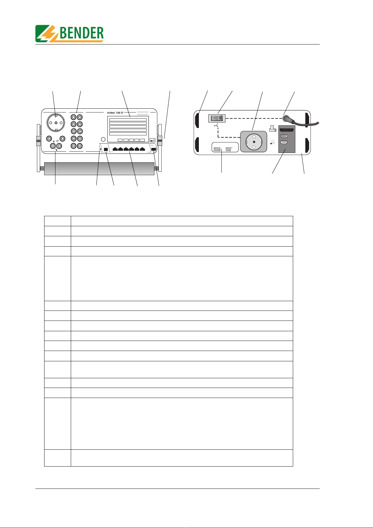
3.5 Operating elements
1 Test socket: The DUT’s power supply cord is plugged in here.
2 10 bushes (1…10) for the connection of patient electrodes.
3 Colour LCD with backlighting
4 Set-up and carrying handle
5 Measuringsockets
- [B] (violet) for the connection of the single-pole measuring cable supplied with the product.
- [A] for the active test probe (TP2) with pushbutton supplied with the product.
- Bush [C] for equipotential bonding (e.g. connection for single-pole line extension with clip
for the testing of permanently installed equipment).
- Bush [D] for functional earth
6 Connection for the TM1000 keypad module integrated in the housing cover.
7Infokey
8Functionkeys1…6
9ENTERkey
10 Positioning feet
11 Power switch with thermo-magnetic circuit breaker
12 Socket outlet with earthing contacts, 16 A for external printer, switched via power
switch (11).
13 Permanently attached power supply cord for connection to the supply voltage.
14 Nameplate
15 Interfaces (viewed from top to bottom):
- Printer Centronics interface for printer connection.
Important: Only connect printers that are not earthed. Follow the
instructions in chapter “Printer” on page 87.
- RS-485 Serial interface for BENTRON® Service
- RS-232 9-pole galvanically isolated serial interface for connection with computer
systems or barcode scanner.
16 Rugged metal enclosure, with pushbuttons for safe storage in the accessories carrier or the
optional carrying bag.
32
1
67
5
BENDER
i
[E]
[C] [D]
[A] [B]
F1 F2 F3 F4 F5
F1: Gerätekatalog
F2: ypenkatalog
F3: Klassifikation
F4: Einzelmessung (Einzelprüfung)
F5: Systemverwaltung
1
2
3
4
56
7
8
9
10
RS 232
BENDER
Unimet 1100 S
Sicherheitstester /Safety- ester
RS 485
4
8
10
14
9
12 13
11
15 16
Operation and setting
15
TGH1256en/10.2005
4. Operation and setting
4.1 Unpacking
Unpack all the parts supplied with the system. Do not use tools with sharp edges which
might damage the content of the package. Compare your order with our delivery note to
check that you have received all products in full. The article number printed on the
nameplates provides an easy means of uniquely identifying each device.
4.2 Commissioning
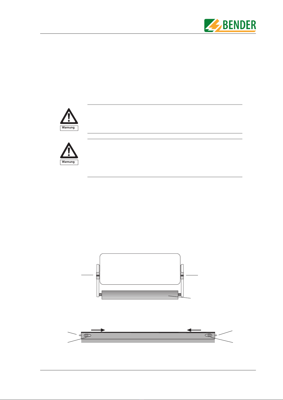
4.2.1 Setting up
Set the UNIMET® 1100ST down on an even surface with the accessories carrier face up. The
carrying handle also serves as a stand so that the UNIMET® 1100ST can be set down on an
even surface. Set up the handle as follows:
1. Pull both adjusting wheels (1) towards the handle (2) and keep hold of them.
2. Move the handle to the required position.
3. Let go of the two adjusting wheels (1). Move the handle a little until the adjusting wheels snap
into place.
4.2.2 Connection of keypad purchased as an optional accessory
1. Push the two grip ends (2) on the fixing axes inwards at the same time. Slot the keypad into
place and let go of the grip ends.
2. Connect the connecting cable for the external keypad to the keypad bush on Unimet.
Check all parts supplied for any evidence of damage in transit. Equipment
damaged in transit must not be used. If a device has sustained damage, please
contact BENTRON®. Details of who to contact are indicated on the delivery
documents.
When storing the devices in an environment where the temperature is wintry
and cold: Leave the devices to stand for 3 to 4 hours at room temperature before
connecting the power supply. When the devices are moved from a cold to a
warm environment, condensation will be evident on all parts. Putting damp
devices into operation risks damaging electrical components and there is a
danger of electric shock on contact.
1
2
1
1
2

Operation and setting
16 TGH1256en/10.2005
4.2.3 Switching on
1. Connect the UNIMET® 1100ST to the supply voltage using the permanently attached power
supply cord.
2. Switch the device on using the power switch.
The test system requires approx. 20 seconds to start up and carry out self testing. The system
tests the system voltage and the voltage to PE. If the test system detects an IT system (e.g.
in the operating theatre) or an error, a message will appear.
If the test system is used other than for the intended purpose, i.e. in an IT system, the
measured values of any leakage currents will not be reproducible. The test result cannot be
used. Disconnect the test system and connect it to an earthed socket outlet.
UNIMET® 1100ST must always be connected to the supply voltage indicated on
the nameplate. Failure to observe this requirement may lead to the test system
and any DUT connected to it sustaining damage.
During testing, the UNIMET® 1100ST test socket is live. Do not touch the earthing
contacts on the socket.
Do not connect DUTs during the start-up phase. If the DUT is faulty, its enclosure
may be live. You risk dangerous electrical shocks by touching it.
The system voltage and automatic adaptation to this voltage are only checked
once UNIMET® 1100ST has started up. Changes to the system voltage made
during active measuring will not be detected. Therefore, before any changes are
made to the system voltage, UNIMET® 1100ST must be switched off via the
power switch. The new system voltage will be detected properly when Unimet is
restarted. If the system voltage is changed without UNIMET® 1100ST having
been switched off in advance, this may damage the current and voltage sources.
UNIMET® 1100ST is a test system for medical electrical and electrical equipment;
it is not an medical electrical device per se. Under no circumstances, therefore,
must patients be connected to UNIMET® 1100ST. Similarly, patients must not be
connected to medical electrical devices connected in turn to UNIMET® 1100ST.
Failure to observe these instructions can lead to hazardous electrical currents.
Operation and setting
17
TGH1256en/10.2005
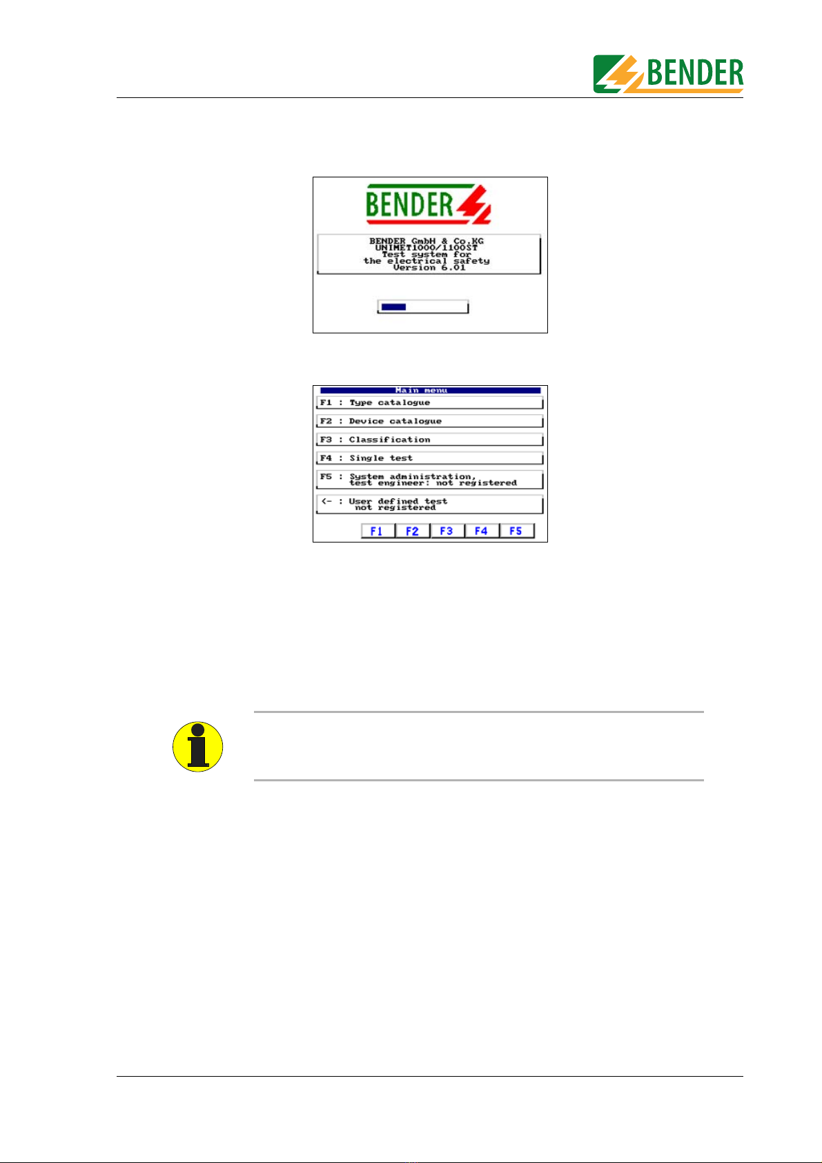
During start-up, the firmware version and company name will be displayed. The company
name can be changed in the system administration settings.
The test system's main menu appears:
The test system is now ready for operation.
4.2.4 Switching off
1. Quit all functions so that the main menu appears.
2. Switch the device off using the power switch.
Data may be lost if you switch the UNIMET® 1100ST off whilst data is being
accessed.
Operation and setting
18 TGH1256en/10.2005
4.3 Principle of operation
4.3.1 Calling up functions
Press the required function key. Press Enter to confirm your entries. The menus take you
through the individual functions.
4.3.2 Entering text and numbers
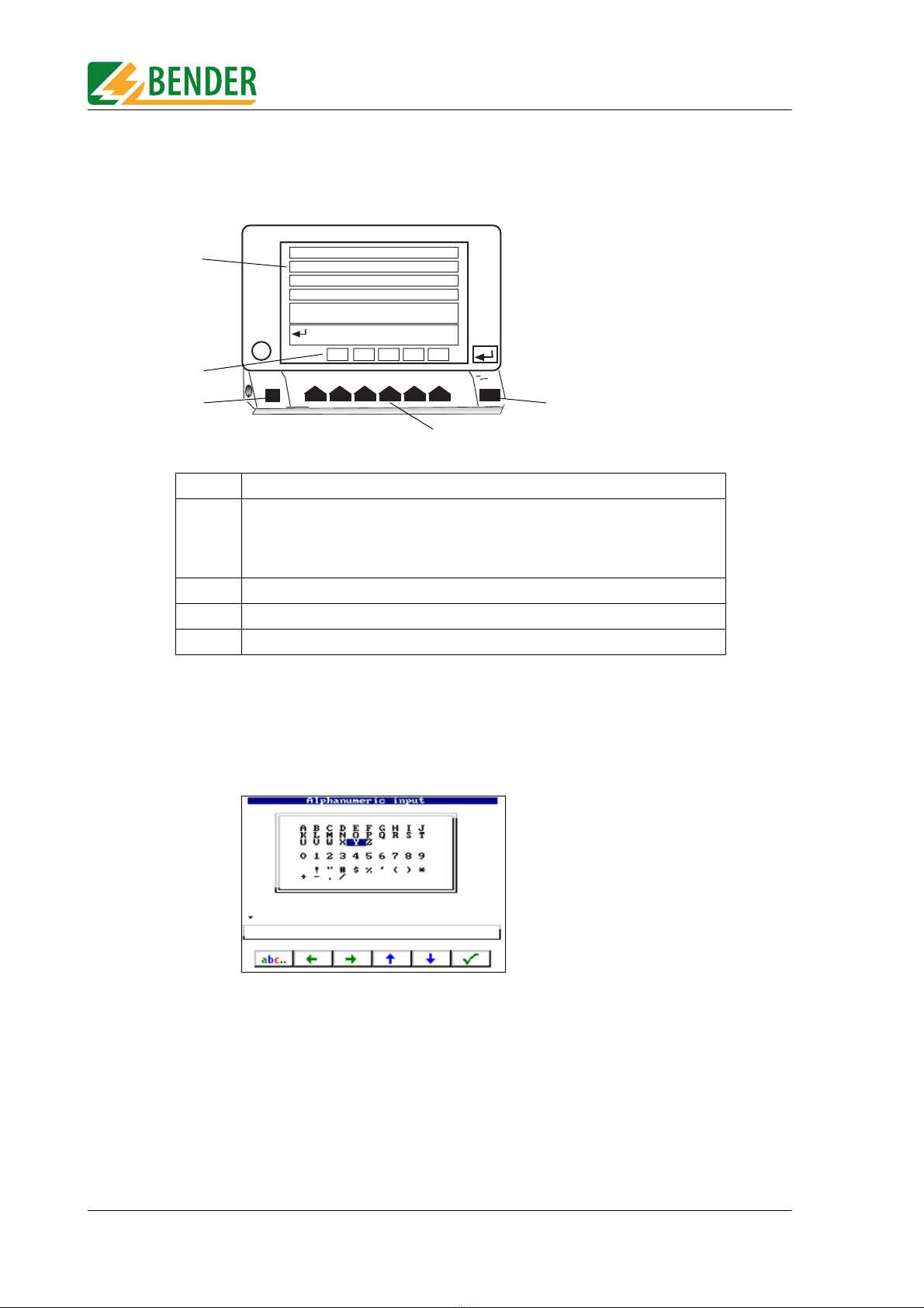
The following input screen will appear if entries need to be made:
Entries can also be made as follows:
●Using the keypad
●By selecting letters and numbers using the arrow keys (on-screen keypad)
●Import via barcode scanner
Press Enter to apply the entries you make via the keypad or on-screen keypad. The Enter
key on the device and Enter on the keypad have the same function.
1 Selection menu (the example shows the main menu)
2 Current assignment of function keys:
F1 Branch to type catalogue
F2 Branch to device catalogue
Etc.
3 The Info key shows the telephone number of the BENTRON® hotline.
4 Function keys are used to activate each function.
5 Press Enter to confirm your entries.
iF1 F2 F3 F4 F5
F1: ype catalogue
F2: Device catalogue
F3: Classification
F5: System administration
test engineer: W. Wacker
F4: Single test
User defined test
not registered
1
3
4
2
5

Operation and setting
19
TGH1256en/10.2005
4.3.2.1 How to use the TM1000 keypad module
Entry and edit operations on the TM1000 keypad module and on the on-screen keypad can
be combined.
4.3.2.2 How to use the on-screen keypad
1. Select a letter or number using the arrow keys.
2. Confirm the character selected by pressing
3. Select the next character and confirm your selection in the same way.
4. To edit characters, press: .
1 The Info key shows the telephone number of the BENTRON® hotline.
2 Function keys are used to activate each function (as on UNIMET® 1100ST).
3 No function
4 Letter keys
5 Shift key for upper case and special characters
6 Up/down arrow keys
7 Enter key (same function as 10, same function as on Unimet)
8 Backspace key, deletes entry to the left of the cursor.
9 Numbers and special characters
10 Press Enter to confirm your entries.
11 Caps Lock key
12 Right/left arrow keys
13 Spacebar
!
1
"
2
§
3
\
45
&
6
/
7
(
8
)
9
=
0
?*
+
QUIOP
AJK
Y;
,:
.CAPS
OCK
WER T Z
SDFGH
XCVBNM
i
F
%
ß
Ü
ÖÄ
<< F1 F2 F3 F4 F5
1
2
12
11
10
9
8
7
6
5
4
3
13
3
abc..

Operation and setting
20 TGH1256en/10.2005
Editing text:
The keys now have the following function:
4.3.3 Selecting catalogue entries
There are various ways of selecting and activating an entry in the type, device or test
engineer names catalogue.
1. Select the entry using the arrow keys. Double arrows can be used to scroll page by page. Once
you have made your selection, activate the entry by pressing the Enter key.
2. Using the keypad, type in the first letter(s) of the entry. If there are a number of similar entries,
you can use the arrow keys to select the required entry. Press Enter to activate the entry.
3. If a barcode scanner is used to read the barcode of an existing entry, this entry is selected
immediately. This provides a means, for example, of starting periodic testing quickly.
Insert character here.
Arrow keys Move change marker to the required position.
Undo previous action.
Delete character here.
Delete entire entry.
+
This manual suits for next models
1
Table of contents
Other Bender Test Equipment manuals


Popular Test Equipment manuals by other brands


Monitech Interlock Systems
Monitech Interlock Systems QuicTest QT-1 Operator's manual

SafeWaze
SafeWaze M2050 User instruction manual

Rigol
Rigol DHO1202 quick guide

COBHAM
COBHAM AEROFLEX 8800S Configuration and Connection Guide

Projecta
Projecta BTL300 operating instructions

Keysight Technologies
Keysight Technologies M8000 Series Getting started guide


