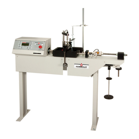
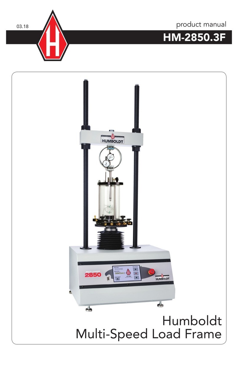
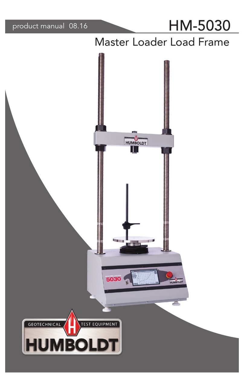
Humboldt Digital MasterLoader HM-3000.3F User manual

product manual
07.08
HM-3000.3F
Humboldt
Digital MasterLoader

TABLE OF CONTENTS
Introduction...........................................................................................1
Applications
Product Use
Product Description
General Warnings ...................................................................... 2
Safety Warnings
Electrical Warnings
Manufacturer’s Rights and Responsibilities ............................... 2
Software Copyright
Important Notice ............................................................................. 3
Updated products............................................................................ 3
Fitness for application...................................................................... 3
Quick Start Guide...................................................................... 4
Startup Scenarios
Installation and Set-up............................................................... 5
Unpacking ........................................................................................ 5
Electrical Connections...................................................................... 5
Instrument Inputs (transducer connections)................................. 5, 6
Mounting Transducers.................................................................. 6, 7
Computer Connection ..................................................................... 7
Additional Device Connection ..................................................... 8, 9
Analogue Device Connection ...................................................... 8, 9
Operation .................................................................................10
Power Switch.................................................................................. 10
Key Function................................................................................... 10
Emergency Stop............................................................................. 10
Set Up Key...................................................................................... 11
Speed Key ...................................................................................... 11
Up Key............................................................................................ 11
Stop Key ......................................................................................... 11
Down Key ....................................................................................... 11
Function Keys ................................................................................. 11
Set-Up Functions ......................................................................12
Set Date ......................................................................................... 12
Set Time ......................................................................................... 13
Set Units ......................................................................................... 14
Set Standards ........................................................................... 14, 15
Set Speed................................................................................. 15, 16
Set Logging Interval....................................................................... 16

©2005 Humboldt Mfg. Co.
Channel Configuration ................................................................... 17
Naming Channel ...................................................................... 17, 18
Set Min ........................................................................................... 18
Set Max .................................................................................... 18, 19
Channel Test Configuration...................................................... 19, 20
Calibration .......................................................................... 21-23
Device ID ........................................................................... 23, 24
Standard Tests ......................................................................... 24
CBR/LBR................................................................................... 24-26
Marshall .................................................................................... 26-28
User Defined Compression ...................................................... 28-30
Soil Cement/TSR ............................................................................ 31
UU Triaxial ...................................................................................... 31
CU Triaxial ...................................................................................... 31
Software .................................................................................. 32
Specifications........................................................................... 33
Test Accessories ...................................................................... 34
Support.................................................................................... 35
Hidden Functions..................................................................... 35
Notes....................................................................................... 36

Introduction
Applications
The HM-3000 Series MasterLoader Compression Testing Frame is designed
for applications requiring multi-purpose loading systems. It is ideal
for Geotechnical laboratories, road construction projects, educational
institutions, and start-up laboratories. Its modular design minimizes initial
costs and allows easy upgrades as desired.
Product Use
This product is intended for use only in accordance with the directions
and specifications contained in this User Guide. Your HM-3000 has been
configured according to your specifications.
The HM-3000 Series Digital MasterLoader has been designed for testing that
complies with ASTM D1883, D2850, D2166, D4767, D5581 and D6927 and
AASHTO T193, T296, T297, T208, T245, T246, and applicable International
standards.
Product Description
The HM-3000 Series Digital MasterLoader has been designed to provide
all the basic functions required to carry out soil (CBR, LBR, Unconfined,
Triaxial), Soil-Cement, and Hot Mixed Asphalt (Marshall, TSR) testing in a
single instrument. Your Compression Testing Frame/Master Loader arrives
factory calibrated for the specific tests you requested.
The HM-3000 Series Digital MasterLoader includes the following key
features:
• Controlofasteppermotordrivenplatenatspeedsfrom0.000001to
3.000000 in/min (or equivalent 00.000001 to 75.000000 mm/min).
• Supportforupto4analoguetransducerinputsfrom0to100mV
suitable for most load, pressure, volume change and displacement
devices. Configuration and calibration capability is provided, and all-
important data is stored in non-volatile memory for safe preservation.
• CompleteDataloggercapacityforthefollowingtests:Triaxials,CBR,
Marshall/TSR, Unconfined Compression, as well as Soil-Cement
tests. All are fully configurable for automated Start, Stop and Logging
conditions and can hold up to 1000 readings per test.
• AlargeLCDscreenand9keymembranepanelforeasypresentation
of results, parameter configuration, and machine control. To protect
against operator misuse, key parameters can only be changed under
pass code control.
1
• PlugandplaySerialport(RS232)communicationswithHumboldt
Material Testing Software (HMTS) for controlling and downloading
stored data.
• UniqueIDandRS485communicationportformultipleunit
connections with a single computer.
In addition, the loader offers a large, backlit LCD display, a touch-sensitive
keypad, a battery-backed real time clock, and auto-conversion of calibration
and speed parameters between English and SI units.
General Warnings
Safety Warnings
Operators should take care to operate this machine under the maximum
load restrictions. The machine is programmed at the factory to provide
safety shutdown if the upper or lower maximum travel is exceeded as well
as if the upper instrument calibration is exceeded.
Electrical Warnings
Typically, there is no reason for the operator to open the machine.
However, if the customer’s engineers attempt to change settings to the
circuit board connected to the back panel, the machine must always be
unplugged before this operation. Unplugging the internal connection to
the back panel circuit board while the machine is under power will result
in permanent damage to the circuit board.
Manufacturer’s Rights and Responsibilities
Software Copyright
COPYRIGHTNOTICE
©2006 HUMBOLDT MFG. CO.
All Rights Reserved.
This manual or parts thereof, may not be
reproduced in any form without the expressed written
permission of HUMBOLDT MFG. CO.
UNPUBLISHEDLICENSEDPROPRIETARYWORK
©2006 HUMBOLDT MFG. CO.
2

The programmable, read-only memory, integrated circuit package
contained in this equipment and covered with a copyright notice label
contains proprietary and confidential software, which is the sole property
of HUMBOLDT MFG. CO. It is licensed for use by the original purchaser
of this equipment for a period of 99 years. Transfer of the license can be
obtained by a request, in writing, from HUMBOLDT MFG. CO.
WiththeexceptionofHUMBOLDTAuthorizedServiceFacilitiesyoumay
not copy, alter, de-compile, or reverse assemble the software in any fashion
except as instructed in this manual. US copyright laws, trademark laws,
and trade secrets protect the materials.
Any person(s) and /or organizations that attempt or accomplish the above
violation or knowingly aid or abet the violation by supplying equipment
or technology will be subject to civil damages and criminal prosecution.
IMPORTANT NOTICE
The information contained herein is supplied without representation
or warranty of any kind. Humboldt MFG. CO. therefore assumes no
responsibility and shall have no liability, consequential or otherwise,
of any kind arising from the use of the described equipment contained
in this manual.
Updated products
The manufacturer reserves the right to change or modify product design
or construction without prior notice and without incurring any obligation
to make such changes and modifications on products previously or
subsequently sold.
Fitness for application
The manufacturer makes no recommendations or claims regarding fitness
for applications other than the specific tests as defined in this User Guide.
3

1
Quick Start Guide
Startup Scenarios
If your HM-3000 was purchased with instrumentation for
one specific test: the instrumentation has been installed and
calibrated. There is no need to configure or calibrate the machine.
It is ready for use.
DO NOT RECALIBRATE!
Refer to the Installation and Setup Section and then proceed to the
section for the specific test desired.
If your HM-3000 was purchased with instrumentation
for multiple tests: one of those tests is ready for use and the
additional tests may or may not require the mounting of a different
transducer than the one that is currently mounted. However all
instrumentation shipped with your unit is calibrated and assigned
specific channels for use. These channels are marked on the
corresponding instrumentation. Unless it is required by your
QC/QA program, there is no need to configure or calibrate the
machine. It is ready for use.
DO NOT RECALIBRATE!
Refer to the Installation and Setup Section and then proceed to the
section for the specific test desired.
If your HM-3000 was purchased without instrumentation
for specific tests: you will need to acquire, check compatibility,
mount and calibrate your instrumentation for use with the
HM-3000.
Refer to the Installation and Setup Section to make sure if your
instrumentation is compatible with the HM-3000. You will need
to calibrate your instrumentation, please refer to configuration and
calibration instructions.You can then proceed to the Section for
the specific test desired.
2
3
4

Installation and Set-up
Unpacking
Initial inspection should include checking for physical damage during
shipping and obvious external damage to the product.
Packagecontentsaredenedbyyourpackinglist.EachMasterLoaderis
configured according to customer specifications. In your inspection, make
certain that the contents of your shipment match the documentation
provided by your packing list.
Placeunitonaatsmoothsurfaceanduselevelingfeet(supplied)anda
bubble level to ensure that the unit is level side-to-side and back-to-front.
Electrical Connections
The HM-3000 is equipped with an internal, digital, switching power supply,
which allows it to be used with most power configurations throughout
the world. The unit is supplied with an IEC electrical cord with a standard
110Vplug.
The HM-3000 arrives ready for operation. Attach the supplied IEC electrical
cord to the machine and plug into a standard wall receptacle for use in the
United States.
For locations other than the U.S., replace the supplied electrical cord with
an IEC cord with the correct plug for your application. The supplied cord
can also be used by cutting the standard plug from the cord and attaching
the correct plug.
Instrument Inputs (load cell/transducer connections)
The HM-3000 has 4 instrumentation inputs located on the back panel to ac-
commodate load cell/transducer connections. This feature allows you to set
up and calibrate up to 4 different instruments, which the unit can quickly
switch between for those needing to do multiple types of tests.
If you purchased load cells/transducers with your unit, they will either be
mounted and calibrated, or in the case of multiple load cells/transducers,
will be calibrated but not mounted. Additional load cells/transducers will
be marked to indicate what input channel was used in the calibration; and,
these load cells/transducers should be connected to the indicated channels.
Third-party load cells/transducers, which are compatible, can also be used
with the HM-3000. Compatible units will have an excitation voltage of
0-10voltsandanoutputof0-100millivolts.Priortouseallthird-party
instrumentationmustbeconguredandcalibratedforuse.Pleasereferto
the Configuration and Calibration sections of this manual.
5

If you are using third-party cables for load cells/transducers connections,
make sure they are wired to be compatible with the HM-3000. Consult
Figure#1foracompatiblereferencewiringdiagram.Plugstoconnect
third-party instrumentation to the Humboldt HM-3000 are available, order
part HM-000474.
Mounting Load Cells and Transducers
If you purchased your HM-3000 with instrumentation, one of the load cell/
transducer setups should already be mounted. If you are using the machine
for multiple tests or want to use instrumentation not included, including
third-party instrumentation, the following photos can be used as a guide for
load cells/transducers setup.
Figure 1. Compatibility wiring diagram for 3rd party cables
Pin3= +dc Output
Pin4= –dc Output
6
Figure 2. Marshall Setup Figure 3. CBR Setup

Computer Connection
Single Device Connection
TheHM-3000canbeconnectedtoaPCcomputertotakeadvantageof
Humboldt’s HMTS software capabilities, conduct real time data logging
and enhanced report generation. This is accomplished via the RS-232 port
on the back panel of the machine (refer to Figures 7 & 8.). Use a RS-232
cable (supplied) and attach it between the computer’s RS-232 port and
the HM-3000.
TheminimumcompatiblecomputercongurationisaPCwithPentiumIII
800MHzprocessor,512MBofRAManda40GBharddrive.Windows2000
orXPwithSP2orlater.
Figure 4. Unconfined Setup Figure 5. UU Triaxial Setup
7
Figure 6. TSR/Soil Cement Setup

Figure 7. Rear panel of HM-3000 showing Analogue Port, RS-232 Port,
RS-485 Input and Output and the four instrumentation channel
inputs.
Multi Device Connection
Multi devices, such as HM-3000s, HM-2325A, HM-2330D MiniLoggers, HM-
2560A, HM-2700A, HM-2700D Direct shear Apparatus can be connected to
a computer via the HM-3000’s RS-485 port. This allows you to daisy-chain
several devices to the same computer; require HM-000375 (RS232 to RS485
converter not included). Use a standard CAT 5 cable (not included) to link
the additional device’s output port to the HM-3000’s RS-485 input port
(refer to Figures 7 & 8). Dip switches need to be set to primary or
secondary usage (see Figure 9).
TheminimumcompatiblecomputercongurationisaPCwithPentium4,
1.2GHzprocessor,512MBofRAM,anda80GBharddriveWindows2000or
XPwithSP2orlater.
Analogue Device Connection
The HM-3000 can be set up to output directly to a chart recorder to provide
a hard copy printout of test results. To accomplish this, connect your chart
recorder via cable attached to the HM-3000’s Analogue port on the back
panel (see Figure 7).
8
69
51
sweepreset not
connected
CH3CH4 CH1CH2
D-SUB, 9-PIN MALE
ANALOG PORT ACCESS
Cable configuration for
analogue port access.
Pins 1, 2, 3 & 4
(Reserved for
Humboldt Chart
Recorder)

Figure 8. Diagram illustrating computer and multiple device connections.
CAT 5 Cable
RS-232 to
RS-485
converter
(HM-000375)
Figure 9. Back Panel electronic board showing location of Dip switches
for setting Computer connections. For single device setups, set
Dip Switch #4 to on (default setting). For multiple device setups,
set Dip Switch #4 to off.
9

Operation
Power Switch
ThePowerSwitchislocatedinthebackpanelontherearofthemachine
above the electrical cord inlet. Also, located between the electrical cord
inletandthePowerSwitchistheFuseCompartment.TheHM-3000usesa
10ampfuse.Tobeginoperation,pressthePowerSwitch.
Figure 10. HM-3000 Power Switch, Electrical Cord Inlet and Fuse
Compartment.
Figure 11. HM-3000 Front Control Panel and Emergency Stop Button
Key Functions
Fuse Compartment.
Emergency Stop
The emergency stop button can be used to stop platen movement quickly.
Pressingthebuttonwillstopplatentravel.Oncetheemergencybuttonhas
been pushed the operator must push the button and pull out the
emergency stop button to clear the emergency stop. Once this has been
done the and buttons can then be used again. If the operator
pulls out the emergency stop button before pressing the button the
machine will emit a high pitched sound until the button has been
pressed.
10

Set Up Key
PushingtheSetUpKeybringsupthemainsetupscreen
from which you can run a test, review your last test, access
the engineering set up menus and set the date, time, units,
standards criteria. This key also is used to return to a previous
screen.
Speed Key
PushingtheSpeedKeyallowsyoutosetthetestspeedsofthe
machine.
Up Key
PushingtheUpKeyallowsyoutomovetheplatenupto
facilitate testing. Also, by pressing and holding down the Up
Key,youcanmovetheplatenupatitsfastestrateofspeed—
3.0"/min.ReleasingtheUpKeyreturnstheplatentoitsset
speed.Whenthekeyispushedthegreenlightnexttoitislit.
Stop Key
PushingtheStopKeystopsplatenmovement.Whenthekeyis
pushed the red light next to it is lit.
Down Key
PushingtheDownKeyallowsyoutomovetheplatendown.
Also,bypressingandholdingdowntheDownKey,youcan
movetheplatendownatitsfastestrateofspeed—2.0"/min.
ReleasingtheDownKeyreturnstheplatentoitssetspeed.
Whenthekeyispushedthegreenlightnexttoitislit.
Function Keys
The four function keys are used to navigate through the
HM-3000’s menu-driven display. The function keys
correspond with the command lines on the HM-3000’s menu
display. F1 corresponds with the first command line; F2, the
second, etc. Command lines that are active in any display will
be proceeded by an (*). If no (*) is present, the corresponding
function key is not active.
11
LOAD 1 0001.2 lb
DISP 1 0.003 in
PRES 1 0.1 psi
VOLU 1 0.1 cc
Except when viewing all four channels values as above left, the function
keys will perform a tare function to the displayed value and "T" will be
displayed next to the channel name to indicate that the value of the
channel has a tare (above right).
LOAD 1 T 0000.0 lb
DISP 1 T 0.000 in
PRES 1 T 0.0 psi
VOLU 1 T 0.0 cc

Set-up Functions
Set Date
To set the Date press until you see this screen:
Press you will see this screen:
Press (DATE/UNIT/STANDARD).Youshouldseethisscreen:
Press (CHANGEDATE).Youshouldseethisscreen:
Press (DATE)toselectthemonth/date/year.Press (INCREASE)
orPress (DECREASE) to change the appropriate number.
To return to any prior screen you can always press
* REVIEW LAST TEST
* RUN TEST
* MORE SETUP
* ENGINEERING SETUP
* SENSOR LIMITS OFF
* RAW_DATA
* MORE SETUP
* RECALL CALIBRATION
* CHANGE DEVICE ID
* DATE/UNIT/STANDARD
* MANUFACTURES INFO
12
* CHANGE DATE
* CHANGE TIME
* UNIT = ENGLISH/METRIC
* STANDARD = ASTM/BS
* DATE = "MM/DD/YY"
* INCREASE
* DECREASE

13
Set Time
To set the Time press until you see this screen:
Press you will see this screen:
Press (DATE/UNIT/STANDARD).Youshouldseethisscreen:
Press (CHANGETIME).Youshouldseethisscreen:
Press (TIME)toselecttheHOURS/MINUTES/SECONDS.Press
(INCREASE).orPress (DECREASE) to change the appropriate number.
To return to any prior screen you can always press
* REVIEW LAST TEST
* RUN TEST
* MORE SETUP
* ENGINEERING SETUP
* SENSOR LIMITS OFF
* RAW_DATA
* MORE SETUP
* RECALL CALIBRATION
* CHANGE DEVICE ID
* DATE/UNIT/STANDARD
* MANUFACTURES INFO
* TIME = "HH/MM/SS"
* INCREASE
* DECREASE
* CHANGE DATE
* CHANGE TIME
* UNIT = ENGLISH/METRIC
* STANDARD = ASTM/BS

14
Set Units
To set the Units the HM-3000 will use to display results, press until
you see this screen:
Press you will see this screen:
Press (DATE/UNIT/STANDARD).Youshouldseethisscreen:
Press (units) to toggle between English and Metric Units.
Selectthestandarddesired—theashingstandardistheactivechoice.
To return to any prior screen you can always press
Set Standards
To set the Standards the HM-3000 will use, press until you see this
screen:
* REVIEW LAST TEST
* RUN TEST
* MORE SETUP
* ENGINEERING SETUP
* SENSOR LIMITS OFF
* RAW_DATA
* MORE SETUP
* RECALL CALIBRATION
* CHANGE DEVICE ID
* DATE/UNIT/STANDARD
* MANUFACTURES INFO
* CHANGE DATE
* CHANGE TIME
* UNIT = ENGLISH/METRIC
* STANDARD = ASTM/BS

15
Press you will see this screen:
Press (DATE/UNIT/STANDARD).Youshouldseethisscreen:
Press (STANDARD)totogglebetweenASTMandBRITISHSTANDARD.
Selectthestandarddesired—theashingstandardistheactivechoice.
To return to any prior screen you can always press
Set Speed
To set the speed of the HM-3000 press You should see this screen:
* REVIEW LAST TEST
* RUN TEST
* MORE SETUP
* ENGINEERING SETUP
* SENSOR LIMITS OFF
* RAW_DATA
* MORE SETUP
* RECALL CALIBRATION
* CHANGE DEVICE ID
* DATE/UNIT/STANDARD
* MANUFACTURES INFO
* CHANGE DATE
* CHANGE TIME
* UNIT = ENGLISH/METRIC
* STANDARD = ASTM/BS
MOTOR SPEED ADJUST
* SPEED = “X.XXXXXX”
* INCREASE
* DECREASE

16
Press (SPEED)tomovebetweenthenumbers.Keeppressing
untilthedigityouwanttochangeisashing.Onceyouhaveselected
the number you want to change, press (INCREASE)or
(DECREASE) to change the number to the desired value.
Set Logging Interval
TosetorchangetheloggingintervalforUSERDEFINEDTESTpress
until the following setup screen appears:
Press you will see this screen:
Press (ENGINEERINGSETUP).Youshouldseethisscreen:
Press (LOGGINGINTERVAL).Youshouldseethisscreen:
Press (TIME) to cycle between the hour/minute/second/tenths to
selectthedesiredincrement.Press (INCREASE)to
(DECREASE) to change to the appropriate number
* REVIEW LAST TEST
* RUN TEST
* MORE SETUP
* ENGINEERING SETUP
* SENSOR LIMITS OFF
* RAW_DATA
* MORE SETUP
* CONFIGURATION
* CALIBRATION
* LOGGING INTERVAL
SAMPLE LOGGING TIME
* TIME = HH:MM:SS.T
* INCREASE
* DECREASE

17
Channel Configuration
If you are adding new instrumentation, changing existing instrumentation
or reconfiguring the HM-3000’s channel setup, you need to configure the
channel for use with the devices you have.
To configure a channel, press You should see this screen:
Press you will see this screen:
Press (ENGINEERINGSETUP).Youshouldseethisscreen:
Press (CONFIGURATION)Youwillbeaskedforapassword,enter:
You should see this screen:
Press (SELECTCHANNEL)toscrollthroughandchoosethechannel
you wish to configure. Once you have selected a channel press
(CONFIGURECHANNEL).Youshouldseethisscreen:
Naming Channel
Fromthepreviousscreen,shownabove,Press (NAME)toselectthe
name you wish to change, press the key until the name you wish to change
is indicated. You should see this screen:
* REVIEW LAST TEST
* RUN TEST
* MORE SETUP
* ENGINEERING SETUP
* SENSOR LIMITS OFF
* RAW_DATA
* MORE SETUP
* CONFIGURATION
* CALIBRATION
* LOGGING INTERVAL
CONFIGURATION screen
* SELECT CHANNEL "CHI"
* CONFIGURE CHANNEL
* CONFIGURE TEST
Table of contents
Other Humboldt Test Equipment manuals

Humboldt
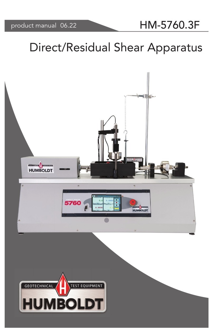
Humboldt HM-5760.3F User manual

Humboldt
Humboldt HM-2750 Series User manual

Humboldt
Humboldt Deluxe Series User manual

Humboldt
Humboldt HM-5470.3F ConMatic IPC User manual

Humboldt
Humboldt H-4374 User manual

Humboldt
Humboldt H-3630A User manual

Humboldt
Humboldt HS-4157 User manual

Humboldt
Humboldt HM-5040.3F User manual

Humboldt
Humboldt HM-5030 User manual

Humboldt
Humboldt HM-4100A User manual