Bender UNIMET 300ST User manual

Operating Manual
UNIMET® 300ST
Testing system for
electrical safety
Software version: 3.2 and later
TGH1365en/10.2012

©Bender GmbH & Co. KG
All rights reserved.
Reprinting only with permission
of the publisher.
Subject to change!
Bender GmbH & Co. KG
Londorfer Str. 65 • 35305 Grünberg • Germany
Postfach 1161 • 35301 Grünberg • Germany
Tel.: +49 6401 807-0
Fax: +49 6401 807-259
E-mail: [email protected]
Web: http://www.bender-de.com

3
TGH1365en/10.2012
Table of Contents
1. How to get the most out of this manual ............................................................. 5
1.1 About this operating manual .............................................................................................. 5
1.2 Technical support .................................................................................................................... 5
1.3 Explanation of symbols and notes ..................................................................................... 6
2. Safety instructions .................................................................................................. 7
2.1 Delivery ........................................................................................................................................ 7
2.2 Intended use .............................................................................................................................. 7
2.3 Skilled persons .......................................................................................................................... 7
2.4 General safety instructions ................................................................................................... 7
2.5 Delivery conditions, guarantee, warranty and liability .............................................. 8
3. System description ................................................................................................. 9
3.1 Function ...................................................................................................................................... 9
3.2 Standard-compliant tests .................................................................................................. 10
3.3 System components ............................................................................................................10
3.4 Controls .................................................................................................................................... 12
4. Operation and configuration ............................................................................. 13
4.1 Commissioning ...................................................................................................................... 13
4.1.1 Connecting a printer ............................................................................................................ 14
4.1.2 Connecting the keyboard and barcode scanner ....................................................... 14
4.2 Principle of operation .......................................................................................................... 14
4.2.1 Operating the device ........................................................................................................... 14
4.2.2 Operation via the keyboard .............................................................................................. 15
4.2.3 Reading in with the barcode reader .............................................................................. 15
4.3 Main menu .............................................................................................................................. 16
4.4 Test engineer catalogue ..................................................................................................... 16
4.5 Device settings ....................................................................................................................... 19
4.5.1 Test probe calibration ......................................................................................................... 20
4.5.2 Device type query ................................................................................................................. 21
4.5.3 Warm-up and cool-down period ..................................................................................... 21
4.5.4 Changing the company name ......................................................................................... 22
4.5.5 Time/date ................................................................................................................................. 22

Inhaltsverzeichnis
4TGH1365en/10.2012
4.5.6 RS-232 parameters ................................................................................................................ 23
4.5.7 Buzzer On/Off ......................................................................................................................... 24
4.5.8 Summer time/winter time ................................................................................................. 24
4.5.9 Language/Sprache ............................................................................................................... 25
4.5.10 Firmware update ................................................................................................................... 25
4.6 Information .............................................................................................................................. 28
5. Testing and measuring ........................................................................................ 29
5.1 Testing via classification ..................................................................................................... 29
5.1.1 Classification ........................................................................................................................... 29
5.1.2 Tests ........................................................................................................................................... 33
5.1.3 Evaluating the test result .................................................................................................... 40
5.2 Recurrent test and device catalogue ............................................................................. 41
5.2.1 Collective printout ................................................................................................................ 42
5.2.2 Backing up the device catalogue .................................................................................... 43
5.3 Single test ................................................................................................................................. 49
6. Maintenance and calibration ............................................................................. 51
6.1 Calibration ............................................................................................................................... 51
6.2 Changing the battery ........................................................................................................... 51
6.3 Error messages ....................................................................................................................... 51
6.4 Disposal .................................................................................................................................... 52
7. Data ......................................................................................................................... 53
7.1 Standards ................................................................................................................................. 53
7.1.1 Application standards ......................................................................................................... 53
7.1.2 Design standards ................................................................................................................... 53
7.2 Test steps .................................................................................................................................. 54
7.3 Technical specifications ...................................................................................................... 56
7.4 Ordering data ......................................................................................................................... 57
INDEX ...........................................................................................................................59

5
TGH1365en/10.2012
1. How to get the most out of this manual
1.1 About this operating manual
This operating manual describes the UNIMET® 300ST with the software version indicated on the cov-
er page. The functions and processes described may vary from those featured in other versions. It is
designed for electrically skilled persons working in electrical engineering and electronics.
Please read this operating manual before using the devices. This documentation must be kept in an
easily accessible location near to the device.
Although great care has been taken in the drafting of this operating manual, it may nevertheless
contain errors and mistakes. The Bender Group cannot accept any liability for injury to persons or
damage to property resulting from errors or mistakes in this manual.
Each of the registered trademarks which appears in this document remains the property of its owner.
1.2 Technical support
As a Bender customer, you will receive technical support and assistance in the event of queries relat-
ing to equipment you have purchased. Please contact our Service Department or your next Bender
agency for more information:
Service-Hotline:
0700-BenderHelp (Telefon und Fax)
Carl-Benz-Straße 8 • 35305 Grünberg • Germany
Tel: +49 6401 807-760 • Fax: +49 6401 807-629
E-Mail: info@bender-service.com • www.bender-de.com

How to get the most out of this manual
6TGH1365en/10.2012
1.3 Explanation of symbols and notes
The following terms and symbols are used to denote hazards and instructions in Bender documen-
tation:
This symbol indicates an immediate risk to life and limb.
Failure to observe the associated instructions and take appropriate precautions
will result in death, serious physical injury or substantial damage to property.
This symbol indicates a potential risk to life and limb.
Failure to observe the associated instructions and take appropriate precautions
may result in death, serious physical injury or substantial damage to property.
This symbol indicates a potentially dangerous situation.
Failure to observe the associated instructions and take appropriate precautions
may result in minor physical injury or damage to property.
This symbol indicates important information about the correct use of the equip-
ment purchased.
Failure to observe the associated instructions can result in equipment malfunc-
tioning or cause problems in the environment in which it is being used.
This symbol indicates tips for using the equipment and particular useful infor-
mation. This type of information will help you to optimise your use of the equip-
ment.
Danger !
Warning
Caution

7
TGH1365en/10.2012
2. Safety instructions
2.1 Delivery
Inspect the dispatch packaging and equipment packaging for damage, and compare the contents
of the package with the delivery documents. Equipment damaged in transit must not be used. If
equipment has been damaged in transit, contact Bender immediately.
Equipment may only be stored in areas where it is protected against dust, damp, spray water and
dripping water and where the specified storage temperatures can be assured.
The selling company’s "General conditions of sale and delivery" always apply.
2.2 Intended use
The UNIMET®300ST has been designed exclusively for use in the area of application stipulated in the
chapter entitled "System description" on page 9.
Intended use also implies:
Observance of all instructions in this operating manual and
Compliance with any test intervals
Use which deviates from or is beyond the scope of these technical specifications is considered non-
compliant. The Bender Group cannot accept any liability for damage resulting from such use.
2.3 Skilled persons
Only electrically skilled persons may work on Bender products. Personnel who are familiar with the
installation, commissioning and operation of the equipment and have undergone appropriate train-
ing are considered skilled persons. Such personnel must have read this manual and understood all
instructions relating to safety.
2.4 General safety instructions
Bender devices are designed and built in accordance with the state of the art and accepted rules in
respect of technical safety. However, the use of such devices may introduce risks to the life and limb
of the user or third parties and/or result in damage to Bender devices or other property.
Only use Bender equipment:
– As intended
– In perfect working order
– in compliance with the accident prevention regulations and guidelines applicable at the loca-
tion of use
Eliminate all faults that may endanger safety immediately
Do not make any unauthorised changes and only use replacement parts and optional accesso-
ries purchased from or recommended by the manufacturer of the equipment. Failure to
observe this requirement can result in fire, electric shock and injury
Information plates must always be clearly legible. Replace damaged or illegible plates immedi-
ately.

Safety instructions
8TGH1365en/10.2012
2.5 Delivery conditions, guarantee, warranty and liability
The conditions of sale and delivery set out by Bender apply.
For software products, the "Softwareklausel zur Überlassung von Standard-Software als Teil von
Lieferungen, Ergänzung und Änderung der Allgemeinen Lieferbedingungen für Erzeugnisse und
Leistungen der Elektroindustrie" (software clause in respect of the licensing of standard software as
part of deliveries, modifications and changes to general delivery conditions for products and servic-
es in the electrical industry) set out by the ZVEI (Zentralverband Elektrotechnik- und Elektronikindus-
trie e.V., the German Electrical and Electronic Manufacturers' Association) also applies.
Delivery and payment conditions along with a copy of the software clause can be obtained from
Bender in printed or electronic format.

9
TGH1365en/10.2012
3. System description
3.1 Function
The UNIMET® 300ST is used to test electrical safety. It has been designed for following areas of use:
Hospital and care beds
"Prüfung nach Instandsetzung, Änderung elektrischer Geräte - Wiederholungsprüfung elek-
trischer Geräte" (Inspection after repair, modification of electrical appliances - Periodic inspec-
tion on electrical appliances) DIN VDE 0701-0702 (VDE 0701-0702):2008-06
with appropriate adapter*also protection class I and II three-phase electrical equipment
according to DIN VDE 0701-0702 and DIN EN 62353
* Use the DS32DCT three-phase current adapter to test devices not being in operation.
Use the DS32A three-phase current adapter to test devices during operation.
The test system supplies measurement results which it evaluates immediately in order to classify the
test as "passed" or "failed". The test sequence which follows classification contains a visual inspection
and a functional test in addition to the electrical tests. The test sequence can be carried out automat-
ically or manually depending on the device under test.
The test results can be displayed on the screen, saved or printed out using an external printer. In the
event of unexpected results, the DUT can be inspected in more detail by carrying out a single test.
The device catalogue provides memory space for the test results from up to 600 tested beds or de-
vices.
Tests can be transferred to a PC software program via the RS-232 interface. This software is included
with the UNIMET®300ST. For recurrent tests, the data stored in the PC software are transferred back
to the UNIMET® 300ST. The RS-232 interface is also used for any subsequent updates of the internal
operating software on the test system.
The test engineer catalogue can be beneficial if more than one person is working with the test sys-
tem. Test engineers already registered on the system are simply selected from this folder. There is no
need to re-enter the name of the test engineer. The names of up to ten test engineers can be stored.
The LC display is backlit. For entering data, a standard keyboard or barcode reader can be connected
to the PS/2 interface.
UNIMET® 300ST has been designed solely for use with earthed systems. If the test
system is used other than as intended, i.e. on an IT system, the measured values
of any leakage currents will not be reproducible. The test result cannot be used.
Alternative measurements of leakage currents, however, carried out with the
UNIMET® 300ST in IT systems will deliver correct test results.

System description
10 TGH1365en/10.2012
3.2 Standard-compliant tests
The UNIMET® 300ST carries out measurements and tests according to the following standards (see
also chapter "7.1 Standards"):
IEC 62353:2007-05
DIN EN 62353 (VDE 0751-1):2008-08
ÖVE/ÖNORM EN 62353:2009-01-01
DIN VDE 0701-0702 (VDE 0701-0702):2008-06
ÖVE E8701-1:03-01
The UNIMET® 300ST carries out the following measurements and tests:
Visual inspection
System voltage
Measurement of current consumption and calculation of power consumption
PE resistance for Protection Class I equipment
Insulation resistance
Equipment leakage current according to the differential measurement method or by direct
measurement
Equipment leakage current -Alternative method
Touch or PE conductor current according to the differential measurement method or by direct
measurement
Functional test
3.3 System components
The following accessories are supplied with the UNIMET® 300ST test system:
1Carrying bag For the storage and transport of the test system
and its accessories. Accessories are kept in the side
pocket and the inside pocket.
2Test probe For testing accessible parts of the DUT
3Test terminal (safety claw grip) For connection to accessible parts of the DUT
4Interface cable (null modem
cable)
Enables data to be exchanged between the test
system and a PC (RS-232 interface)
5Calibration certificate Proof of the calibration carried out in the factory
6Technical device manual on CD Test system manual
7UNIData300 PC software (CD) UNIData300 software for
- backing up the device catalogue on a PC
- transferring a firmware update to the
UNIMET® 300ST
8VK701-6 Adapter Schuko
(German)
For testing extension cables and socket strips
9VK701-7 Adapter for non-
heating appliances
For testing device connecting cables
10 USB1.1 RS-232 converter Enables data exchange between the RS-232
interface of the UNIMET® 300ST and the USB port
of a PC (with installation CD)

System description
12 TGH1365en/10.2012
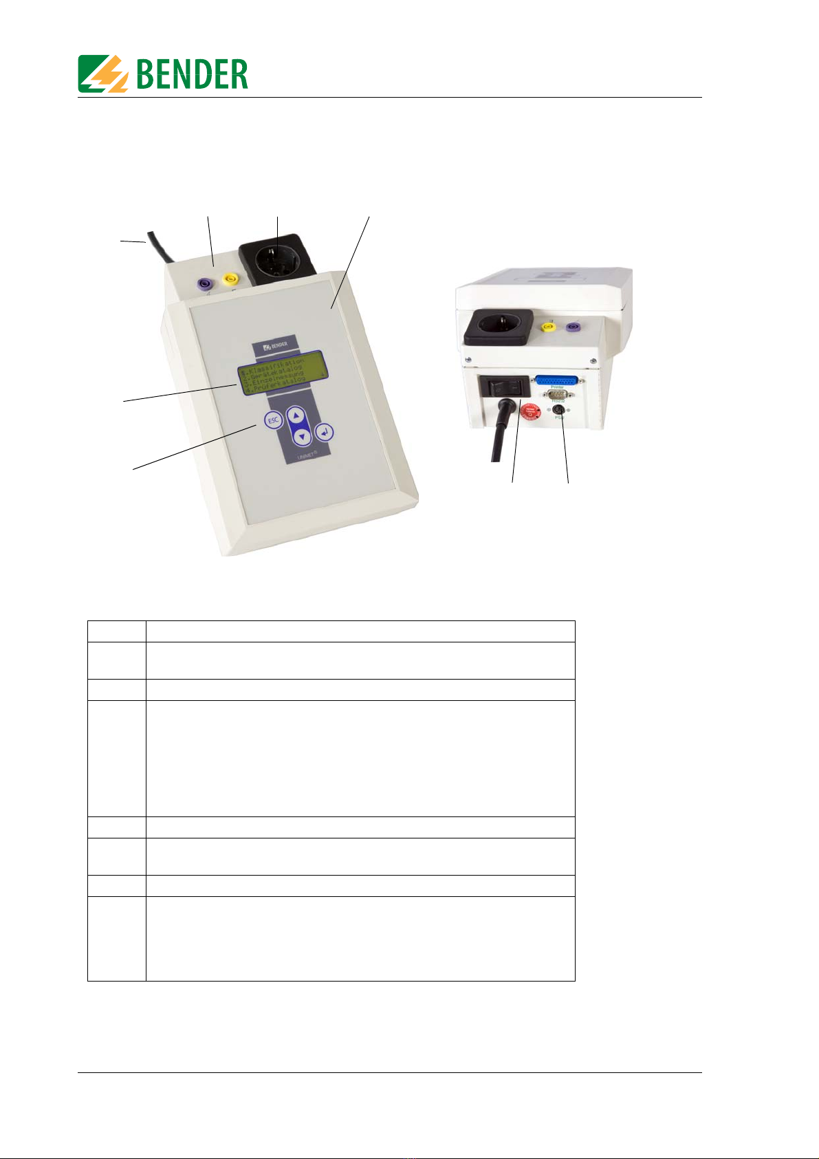
3.4 Controls
1 Control buttons
2 Backlit LCD for displaying the user menu and the measurement results. Four
lines of 20 characters each.
3 Permanently attached power cable for connection to the supply voltage.
4Sockets
- violet: Connection for test probe for testing accessible parts of the
device under test.
- yellow (E): for a second measuring lead when the low-resistance continuity
of the PE conductor is to be measured between two points (e.g.,
on single-phase, permanently installed devices or extension
cables).
5 Test socket: This is where the DUT's power supply cable is plugged in.
6 Durable plastic enclosure, with pushbuttons for safe storage in the carrying
bag.
7 Power switch with thermo-magnetic circuit-breaker.
8Interfaces
- RS-232 interface, 9-pin, galvanically isolated, for connection to a PC
- Centronics interface for connection to a printer
- PS/2 port for connection to an external standard keyboard and a barcode
reading wand or scanner.
2
8
7
6
5
4
3
1
13
TGH1365en/10.2012
4. Operation and configuration
4.1 Commissioning
1. Lay the UNIMET® 300ST down on an even surface with the coloured edges of the bag facing
up. Open the two covers (Velcro fasteners).
2. Connect the UNIMET® 300ST to the supply voltage using the permanently attached power
cable.
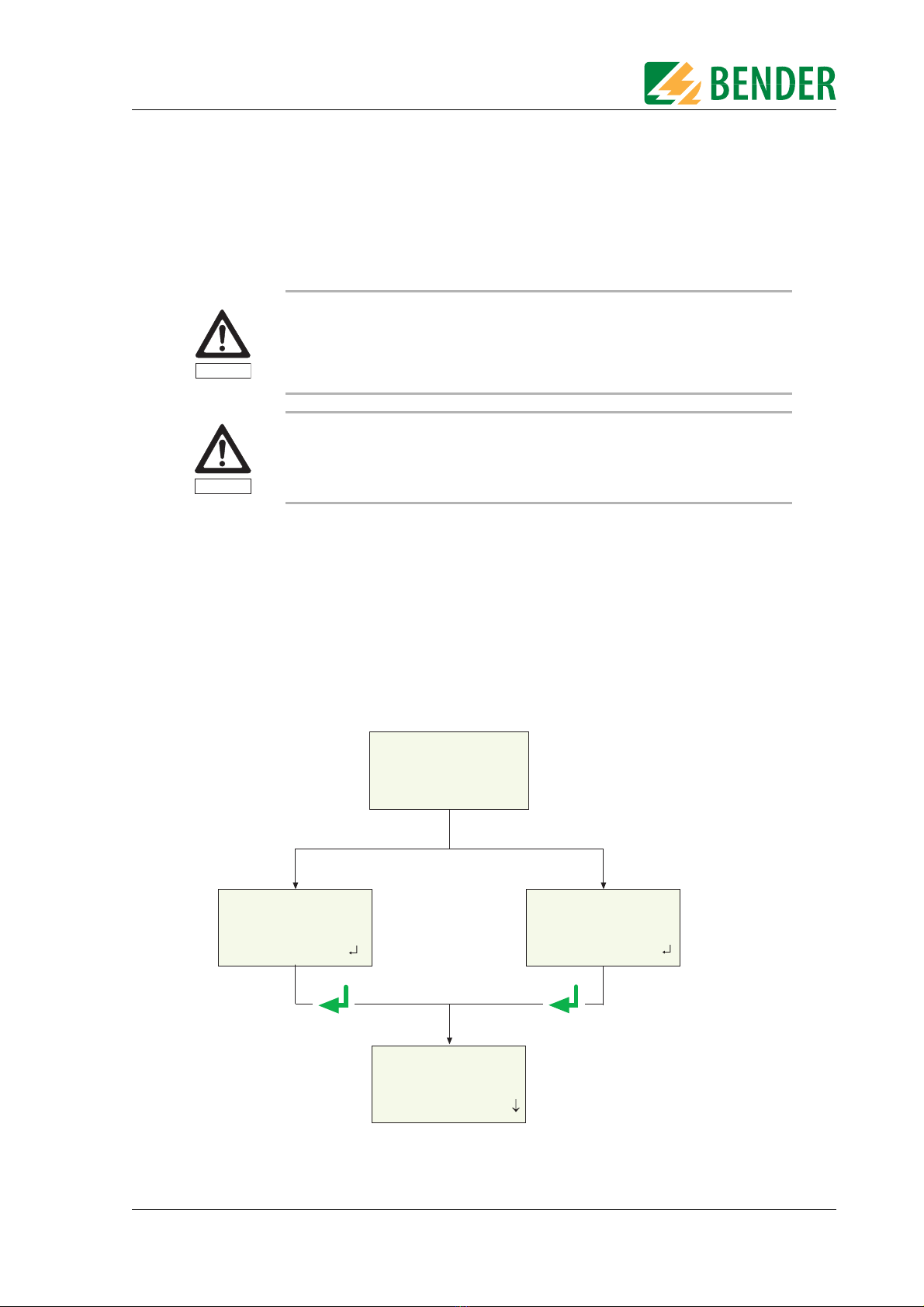
3. Switch on the device using the power switch.
The test system logs on with a beep (only when the buzzer is switched on) and displays the welcome
text:
The test system is now ready for operation. The main menu appears.
Inspect UNIMET® 300ST, its supply cable and measuring leads connected to it for
visible damage on the outside. Do not operate equipment showing any visible
damage.
The UNIMET® 300ST must always be connected to the supply voltage indicated
on the nameplate. Failure to observe this requirement may damage the test sys-
tem and any device under test connected to it.
Warning
Caution
------------------------------
Test eng. logged on:
Hofmann
Next:
** WARNiNG **
No test engineer
logged on!
Next:
UNIMET300ST
Test system for
electrical safety
BENDER GMBH & CO.KG
1. Classification
2. Device catalogue
3. Single test
4. Test eng. catalog
If no test engineer
has logged on yet
If a test engineer has
already logged on
Main menu
Press the ENTER key
or wait 3 seconds
leads to main menu

Operation and configuration
14 TGH1365en/10.2012
4.1.1 Connecting a printer
A printer can be connected to print out the test results. Providing that:
The printer used has an IBM 8-bit character set
The printer is set to IBM emulation
GDI printers (GDI = Graphic Device Interface) are not suitable for the UNIMET®300ST.
You need a standard printer cable (25-pole D-Sub plug to Centronics) to connect the printer. This ca-
ble is not included with the equipment.
4.1.2 Connecting the keyboard and barcode scanner
A keyboard and/or barcode reading wand or barcode scanner can be used to make it easier to input
the ID numbers and names of test engineers. UNIMET® 300ST supports the PS/2 interface to which
either a standard keybboard, a PS/2 barcode-pen reader or PS/2 barcode scanner can be connected.
If an AR100 barcode-pen reader is connected to a PS/2 keyboard switch cable (see “Ordering data”
auf Seite 57.), it can be connected to a keyboard at the same time. If no keyboard is connected, then
plug the keyboard simulator supplied with the AR100 barcode-pen reader to this port.
The keyboard and barcode pen reader or barcode scanner can be plugged in and unplugged during
operation. Adjustments on the UNIMET are not necessary. The keyboard and barcode pen reader
must not be connected before switching on the UNIMET. This increases flexibility during testing.
When the UNIMET detects a PS/2 keyboard, then the "Num-Lock" LED lights up. The LED indicates
that the keyboard is ready.
4.2 Principle of operation
4.2.1 Operating the device
All the functions of the UNIMET®300ST are controlled using the four control keys and the displays on
the screen. The current position on the menus is indicated by a flashing marker (cursor).
Earthed printers can affect the measurements. Therefore, during the measure-
ments, make sure that either
- the Centronics interface is not connected to an earthed printer or
- the Centronics interface is electrically isolated via a suitable component.
Use the arrow buttons to move the cursor up or down on the menus.
Use the Enter button to confirm selection of the current menu item.
ESC The ESC button enables you to leave functions without making
changes. It also enables you to return to the main menu.
Caution

Operation and configuration
15
TGH1365en/10.2012
4.2.2 Operation via the keyboard
An external keyboard makes it easy to enter the names and ID numbers of the test engineers. You
can also operate the UNIMET entirely via the keyboard. The Cursor block " ", " ", " " "ENTER"
and "ESC" keys have the same function as the buttons on the front of the UNIMET.
Note when entering text:
The text entry cannot be longer than 20 characters. The UNIMET will truncate longer entries to
20 characters.
You can enter all characters which can be selected directly on UNIMET.
Upper and lower case is available but not umlauts.
The numeric keypad can only be used to enter digits. The LED "Num-Lock" therefore lights up
constantly.
When entering text, the following keys can be used to edit the text:
" ", " " (Cursor block), " " (Backspace), Del, Home.
Entries via the keyboard can also be combined with texts read in from the barcode scanner and
barcode reading wand.
Save the entry after entering the last character by
– by holding down the Enter button " " on the UNIMET for approx. 3 seconds
– or by pressing the " " ENTER key on the keyboard once.
4.2.3 Reading in with the barcode reader
Refer to the operating instructions for the barcode reading wand or barcode scanner.
The AR100 barcode reading wand (see “Ordering data” auf Seite 57.) reads more reliably by sweep-
ing it quickly over the barcode. Also follow the instructions for the barcode reading wand. Barcodes
can be read both forwards and backwards.
The data string which is read in can be up to 20 characters long. The UNIMET will truncate longer en-
tries to 20 characters.
When reading in the names and ID numbers of new test engineers, the input screen will remain
open. This allows you to check the entry and change or replace it if necessary. .
You can delete the entry and go to the previous menu by holding down
– the "ESC" button on the UNIMET for approx. 3 seconds
– or by pressing the "ESC" key on the external keyboard once.
Save the entry by holding down
– the Enter button " " on the UNIMET for approx. 3 seconds
– or by pressing the " " Enter key on the external keyboard once.
You can use the barcode scanner or barcode reading wand to call up tests from the device catalogue
again using the ID number. In this case, after successfully reading in the barcode, it will immediately
switch to the next screen of the operating process.

Operation and configuration
16 TGH1365en/10.2012
4.3 Main menu
All UNIMET®300ST functions and submenus can be accessed from the main menu.
Each submenu is accessed by selecting it with the arrow buttons and confirming by pressing the
" " button.
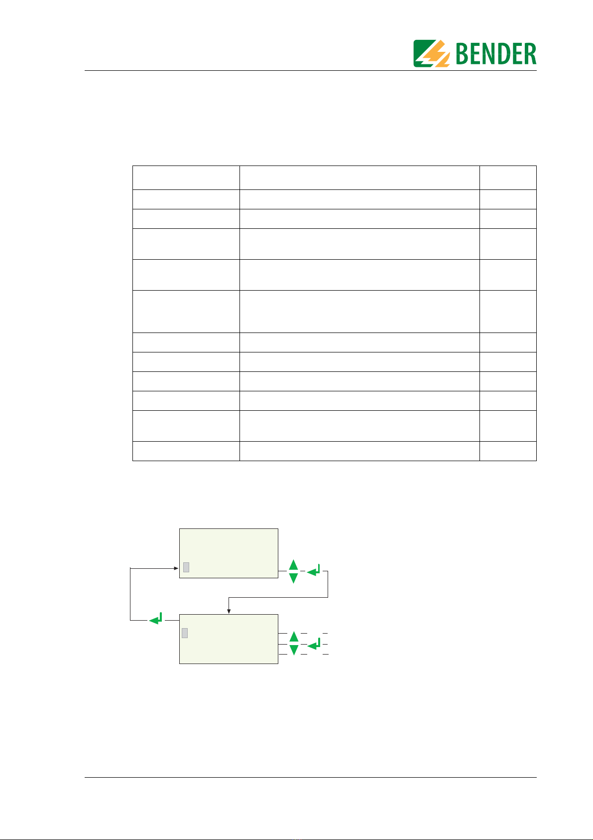
4.4 Test engineer catalogue
The names of the test engineers are stored in the "Test engineer catalogue".The test engineer whose
name appears in the test protocol is also logged on here. You should therefore set the name of the
test engineer before carrying out the first test.
The test catalogue can be particularly beneficial if more than one person is working with the test sys-
tem. Test engineers already registered on the system are simply selected from the test catalogue us-
ing the arrow buttons. There is no need to re-enter the name of the test engineer.
A name of a test engineer cannot be longer than twenty characters. The names of up to ten test
engineers can be stored.
Menu item Function Page
1. Classification Answer the questions that appear on the screen. The
test system will identify the required test steps and
limits to be observed. The assisted test sequence will
guide you through all necessary steps to be taken.
29
2. Device catalogue The test results, tests and limits of the device tested by
the test system are stored in the device catalogue.
41
3. Single test Test steps can be called up in the form of single tests
and repeated as often as required.
49
4. Test engineer
catalogue
Select test engineer, enter new test engineer, delete
test engineer
16
5. Device setting Settings for test probe, type query, warm-up period,
company name, clock, RS-232 interface, buzzer,
language and update
19
6. Info Provides information about the device names,
software version and serial number of the device.
28
Main menu
1. Select "Test eng. catalog."
ESC - Select and log on test engineer
- Enter and log on new test engineer
- Delete existing test engineer
2. select required function:
1. Exit
2. Select test eng.
3. Enter new test eng
4. Delete test eng.
1. Classification
2. Device catalogue
3. Single test
4. Test eng. catalog.

Operation and configuration
17
TGH1365en/10.2012
Select the name of a test engineer (log on) as follows:
To enter the name of a new test engineer:
SELECT TEST ENGINEER
Test engin.: ( 3/ 4)
HENRY STONE
Select: , Confirm:
1. Call up
“Select test eng.” function
2. Use the arrow keys to select
the test engineer
3. Confirm with ENTER key
-----------------------------
Test eng. logged on:
HENRY STONE
-----------------------------
Selected test engineer is
displayed for approx. 3 seconds
ESC
1. Exit
2. Select test eng.
3. Enter new test eng
4. Delete test eng.
ENTER TEST ENG. NAME:
_
Char.: A-Z, 0-9, -. /
Exit: ESC Next:
1. Select “Enter new test eng”
2. Use the arrow keys to select the first characters
and then press the ENTER key
4. After entering the last character,
press and hold down the
ENTER key for approx. 3 seconds.
3. Select all the remaining characters also
Briefly press the ESC key
= edit previous character
Press and hold down the ESC key
= Exit menu without making changes
The new test engineer is
saved and logged on
3 s
ENTER TEST ENG. NAME:
JOHN MEYER
Char.: A-Z, 0-9, -. /
Exit: ESC Next:
ESC
ESC
ESC
ESC
1. Exit
2. Select test eng.
3. Enter new test eng
4. Delete test eng.
1. Exit
2. Select test eng.
3. Enter new test eng
4. Delete test eng.

Operation and configuration
18 TGH1365en/10.2012
To delete the name of a test engineer:
1. Call up “Delete test eng.”
function
2. Use the arrow keys to select
the test engineer
3. Confirm with ENTER key
Confirmation is displayed
for approx. 3 seconds
The selected test
eng. will be deleted
from the catalogue.
Please wait!
1. Exit
2. Select test eng.
3. Enter new test eng
4. Delete test eng.
SELECT TEST ENGINEER
Test engin.: ( 3/ 4)
PETER MILLER
Select: , Confirm:
ESC
Operation and configuration
19
TGH1365en/10.2012
4.5 Device settings
Some of the following settings are used in generating reports to record the test
results. You should therefore check these settings before carrying out the first test.
To access the device settings:
Menu item Function Page
1. Exit Returns to the main menu -
2. Test probe calibration Zero calibration test probe 20
3. Device type query This is where you determine whether another device type
is to be queried and stored in addition to the device ID.
21
4. Warm-up/cool-down Setting for devices which require a warm-up period before
the test and cool-down period after the test.
21
5. Change comp. name The company name entered here will appear on the
printout of the test report and after switching on the
device on line 4 of the welcome menu.
22
6. Time/date Set system time and date 22
7. RS-232 parameters Set data transfer speed 23
8. Buzzer On/Off Switch buzzer on or off 24
9. Summer/wintertime Automatic switchover from summer time to winter time 24
10. Language/Sprache Select German or English for user menus and protocol
text. Activate settings for use in Austria.
25
11. Firmware update Load new version of operating software 25
Main menu
1. Select “Device setting”
ESC 2. Select required function
1. Exit
2. Test probe calibr.
3. Device type query
4. Warm-up/cool-down
2. Device catalogue
3. Single test
4. Test eng. catalog.
5. Device setting

Operation and configuration
20 TGH1365en/10.2012
4.5.1 Test probe calibration
Zero balance must be carried out for the UNIMET® 300ST test probe. As with an ohmmeter, this en-
sures that the ohmic resistance of the test probe will not affect the PE conductor test result.
Recalibrate each time after connecting
– another test probe,
– another measuring lead,
– or a three-phase adapter
to the test system.
Proceed as follows to calibrate the test probe:
*) With permanently connected Protection class I devices or extension cables al-
so, the low resistance continuity of the PE conductor can be tested. The measure-
ment is carried out between the test probe and the measuring lead connected to
the yellow socket E.
Before the test, a single zero calibration must be carried out with the test probe
and the measuring lead.
Carry out a zero calibration again if you want to run the PE conductor test with
the test probe on equipment with Schuko plug.
Failure to follow these instructions may lead to false test results.
Device setting
1.Select “Test probe calibr.”
2. Hold the test probe on the earth contact
of the test socket*).
Make sure that the test probe
remains there during the entire
calibration process.
*** CALIBRATION ***
Insert test probe
and contact PE of
socket outl. Next:
*** CALIBRATION ***
Testprobe/Cable
Please wait !
3. Start calibration.
1. Exit
2. Test probe calibr.
3. Device type query
4. Warm-up/cool-down
ESC
Table of contents
Other Bender Test Equipment manuals


