Bendix CVS SmarTire Trailer-Link User manual

SmarTire Trailer-Link™TPMS
Tire Pressure Monitoring System
Operator’s Manual
This booklet contains important operational and safety
information that benets you and subsequent owners.

2
The trademarks used in this document, including Bendix™, are United States
trademarks owned by or licensed to Bendix Commercial Vehicle Systems LLC.
Sources of Additional Information about
your SmarTire®System by Bendix™CVS
Consult the vehicle manufacturer’s documentation.
Visit www.bendix.com for free downloads of these
publications from the Literature Center at www.bendix.com.
BW2799 SmarTire Tire Pressure Monitoring System
(TPMS) Operator’s Manual
BW2809 SmarTire TPMS Hand Tool Manual
BW2820 SmarTire Low Frequency (LF) Tool Users Manual
BS2822 SmarTire TPMS Walk Around Card
or
Contact the Bendix Tech Team at
techteam@bendix.com or
1-800-AIR-BRAKE (1-800-247-2725, option 2).
Representatives are available
Mon. - Fri. 8:00 a.m. to 6:00 p.m. ET.

3
INDEX
About the SmarTire®TPMS and SmarTire Trailer-Link™TPMS . . . . . . . . 5
Section A - System Overview . . . . . . . . . . . . . . . . . . . . . . . . . 7
1.0 System Overview. . . . . . . . . . . . . . . . . . . . . . . . . . . 7
1.1 System Components . . . . . . . . . . . . . . . . . . . . . . . . . 7
1.2 Maintenance Tool. . . . . . . . . . . . . . . . . . . . . . . . . . . 7
1.3 How Does The SmarTire Trailer-Link™TPMS System Work?. . . . 8
1.4 Fundamentally, Why Is Temperature Monitoring Important?. . . . . 9
2.0 Tire Maintenance. . . . . . . . . . . . . . . . . . . . . . . . . . . 12
Section B - System Installation – Tire Sensors . . . . . . . . . . . . . . . . 14
3.0 System Installation: Tire Sensors . . . . . . . . . . . . . . . . . . 14
3.1 Sensor Overview . . . . . . . . . . . . . . . . . . . . . . . . . . . 14
3.2 Tools Required . . . . . . . . . . . . . . . . . . . . . . . . . . . . 14
3.3 Tire Sensor Installation. . . . . . . . . . . . . . . . . . . . . . . . 15
3.4 Re-mounting Tires After A Sensor Has Been Installed . . . . . . . 16
3.5 Removing A Tire That Has A SmarTire®Sensor Installed . . . . . . 20
3.6 Tire Sensor Specications . . . . . . . . . . . . . . . . . . . . . . 22
Section C: System Installation – Components and Programming. . . . . . . 23
4.0 Installing The SmarTire Trailer-Link System . . . . . . . . . . . . . 23
4.1 Conguring & Customizing Your SmarTire Trailer-Link System . . . 27
4.2 SmarTire Trailer-Link Axle CIP Adjustment Instructions . . . . . . . 28
Section D: SmarTire Trailer-Link Display Options . . . . . . . . . . . . . . .34
5.0 Trailer Information Display Options . . . . . . . . . . . . . . . . .34
5.1 Tractor SmarTire Dash Display. . . . . . . . . . . . . . . . . . . . 34
5.2 Tractor SmarTire Dash DisplayAlerts . . . . . . . . . . . . . . . .35
5.3 Trailer-Link To SmarTire Dash Display Link-Up Procedure . . . . . 35
5.4 Trailer Lamp Blink Codes. . . . . . . . . . . . . . . . . . . . . . .35
Section E: Additional Component Details . . . . . . . . . . . . . . . . . . . 37
6.0 Trailer-Link System Component Details . . . . . . . . . . . . . . .37
6.1 Trailer-Link Module Specications . . . . . . . . . . . . . . . . . . 37
Section F: Troubleshooting . . . . . . . . . . . . . . . . . . . . . . . . . . 41
7.0 Troubleshooting Guide . . . . . . . . . . . . . . . . . . . . . . . . 41
7.1 SmarTire Gauge Display And Trailer-Link Module Q&A . . . . . . . 41
7.2 SmarTire System Q&A . . . . . . . . . . . . . . . . . . . . . . . .46
7.3 Diagnosing A Defective, Missing, Or Misplaced Sensor . . . . . . . 46
7.4 SmarTire Hand Tool Troubleshooting . . . . . . . . . . . . . . . . 47
Appendix 1: Replacement Parts . . . . . . . . . . . . . . . . . . . . . . . . 48
8.0 Replacement Parts. . . . . . . . . . . . . . . . . . . . . . . . . .48
Appendix 2: System Scope Of Use & Alerts. . . . . . . . . . . . . . . . . .49
9.0 System Scope Of Use And Alerts . . . . . . . . . . . . . . . . . . 49
9.1 System Installation And Usage. . . . . . . . . . . . . . . . . . . .49
9.2 Use Of Chemicals . . . . . . . . . . . . . . . . . . . . . . . . . . 49
9.3 Reacting To Alerts . . . . . . . . . . . . . . . . . . . . . . . . . .49
9.4 FCC Notice . . . . . . . . . . . . . . . . . . . . . . . . . . . . . .50

4
GENERAL SAFETY GUIDELINES
WARNING! PLEASE READ AND
FOLLOW THESE INSTRUCTIONS
TO AVOID PERSONAL INJURY OR DEATH:
When working on or around a vehicle, the following
guidelines should be observed AT ALL TIMES:
▲Park the vehicle on a level surface, apply the parking
brakes and always block the wheels. Always wear
personal protection equipment.
▲Stop the engine and remove the ignition key when
working under or around the vehicle. When working
in the engine compartment, the engine should be shut
off and the ignition key should be removed. Where
circumstances require that the engine be in operation,
EXTREM E CAUTION should be used to prevent personal
injury resulting from contact with moving, rotating,
leaking, heated or electrically-charged components.
▲Do not attempt to install, remove, disassemble or
assemble a component until you have read, and
thoroughly understand, the recommended procedures.
Use only the proper tools and observe all precautions
pertaining to use of those tools.
▲If the work is being per formed on t he vehicle’s air brake
system, or any auxiliar y pressur ized air systems, make
certain to drain the air pressure from all reservoirs
before beginning ANY work on the vehicle. I f the vehicle
is equipped with a Bendix® AD-IS® air dryer system, a
Bendix® DRM™ dryer reservoir module, or a Bendix®
AD-9si® air dryer, be sure to drain the purge reservoir.
▲
Following the vehicle manufacturer’s recommended
procedures, deactivate the electrical system in a manner
that safely removes all electrical power from the vehicle
.
▲Never exceed manufacturer’s recommended pressures.
▲Never connect or disconnect a hose or line containing
pressure; it may whip. Never remove a component or
plug unless you are certain all system pressure has
been depleted.
▲ Use only genuine Bendix® brand replacement parts,
components and kits. Replacement hardware, tubing,
hose, ttings, etc. must be of equivalent size, type
and strength as original equipment and be designed
speci cally for such applications and systems.
▲Components with stripped threads or damaged parts
should be replaced rather than repaired. Do not
attempt repairs requiring machining or welding unless
speci cally stated and approved by the vehicle and
component manufacturer.
▲Prior to returning the vehicle to ser vice, make c ertain all
components and systems are restored to their proper
operating condition.
▲ For vehicles with Automatic Traction Control (ATC),
the ATC function must be disabled (ATC indicator
lamp should be ON) prior to performing any vehicle
maintenance where one or more wheels on a drive a xle
are lifted off the ground and moving.
▲The power MUST be temporarily disconnected
from the radar sensor whenever any tests USING A
DYNAMOMETER are conducted on a Bendix® Wingman®
Advanced™-equipped vehicle.
▲You should consult the vehicle manufacturer's
operating and service manuals, and any related
literature, in conjunction with the Guidelines above.

5
About the SmarTire® Tire Pressure Monitoring
System (TPMS) and SmarTire Trailer-Link™ TPMS
Full SmarTire®TPMS System Overview
Thankyoufor purchasing theSmarTireTrailer-Link™Tire PressureMonitoring
System (TPMS) by Bendix CVS. With SmarTire Trailer-Link TPMS onboard,
your vehicle is equipped with a wireless communication network allowing
seamless integration of wireless tire pressure sensing technology.
The SmarTire Trailer-Link TPMS system is an advanced tire pressure
monitoring system specically designed for commercial vehicle trailers. The
system monitors the pressure and temperature of each trailer tire in order
to provide real-time, tire status information and to warn the driver of a tire-
related problem before it becomes dangerous.
Bendix SmarTire System Advantages
●Extends tire life;
●Reduces maintenance costs and time;
●Helps maximize fuel economy by ensuring that tires are properly inated;
●Reduces trailer downtime; and
● Reduces accident risk caused by a tire blowout or tire re.
System Features
●Temperature compensated alerts: Know when your tires are at risk no
matter how long you’ve been driving;
●Real-time trailer tire information displayed on the dash whenever the
tractor is equipped with the SmarTire TPMS system by Bendix CVS;
●Tire alerts provide instant visual warning of a tire problem using the
tractor’s dash display or a trailer lamp;
●There are three types of tire alerts: Pressure Deviation Alert, Critical
Low Pressure Alert, and High Temperature Alert;
●The SmarTire Trailer-Link system data can be sent through the tractor’s
J1939 communication network via the tractor-mounted SmarTire TPMS
for seamless vehicle integration; and
●The trailer tire data can be broadcast on the J1939 communication
network and accessed by telematics devices for back-ofce reporting
of tire data.

6
IMPORTANT NOTICE: PLEASE READ
To prevent sensor damage, when mounting and dismounting tires that
have SmarTire®TPMS tire sensors, be sure that the maintenance facility
is aware that a tire pressure monitoring system is installed.
If any rims are relocated or replaced, be sure to follow the SmarTire by
Bendix system guidelines to permit the system to re-learn the tire sensor
positions.
To monitor your trailer tires with your existing SmarTire by Bendix tractor
ECU, you must ensure that the SmarTire Trailer-Link™enable function
is set to ON in the SmarTire TPMS system tractor-mounted ECU (part
number 200.0216).
Additionally, for tractors equippedwithECUpartnumber200.0184,inorder
for the ECUto be able tocommunicatewiththeSmarTireTrailer-LinkECU,
the ECU rmware MUST BE updated to new rmware. For instructions
on performing this update, please contact your Bendix account manager
or call 1-800 AIR-BRAKE (1-800-247-2725), option 2.

7
Section A - System Overview
1.0 System Overview
1.1 System Components
Figure 1 - System Components and Hand Tool
ECU. The Electronic Control Unit (ECU) of the SmarTire Trailer-Link™Tire
Pressure Monitoring System receives data transmissions from individual tire
sensorsmountedoneach trailerwheel. Theinformationreceived iscompared
to user-dened settings. An alert is triggered if the system detects that a tire
is under-inated and/or above expected temperatures.
Where the tractor is equipped with Bendix™SmarTire®TPMS, the data
and alerts are communicated to a dash display along with the tractor tire
information. Alternately, where the tractor is not equipped with a SmarTire
TPMS system, the Trailer-Link system alerts the driver using an optional
trailer-mounted lamp.
Sensors. Designed for the harsh environment of a commercial truck tire,
each tire sensor is mounted in a break-away cradle for extra protection.
The tire sensor measures internal tire pressure and temperature every 12
(twelve) seconds and transmits data every three to ve minutes. If the system
detects a pressure change of 3 PSI (0.206 bar) or greater, it does not wait
until the next transmission, but will transmit the data immediately.
Sensor Straps. Sensors are mounted to the surface of the rim using a
stainless steel strap, a reliable and universal method of sensor installation.
Harness. Designed to not require a separate power supply, the harness
supplies trailer ABS system power to the SmarTire Trailer-Link Tire Pressure
Monitoring System ECU.
1.2 Maintenance Tool
Maintaining tires in the yard is just as important as real-time tire information
for the driver, but many TPMS systems don’t include functionality to help
yard maintenance personnel. The SmarTire universal hand tool acts like an
“electronic billy-club” allowing maintenance personnel to wirelessly ‘ping’
each tire to measure its pressure and temperature. The SmarTire hand tool
reduces diagnostic time and helps keep every tire rolling safely and cost-
effectively. (For the Maintenance Tool manual, see BW2809.)
Harnesses
Stainless Steel
Tire Straps Trailer-Link ECU
Tire Sensors
and Cradles
Maintenance
Hand tool

8
1.3 How Does The SmarTire Trailer-
Link™ TPMS System Work?
Full SmarTire®TPMS System Overview
1. The SmarTire Trailer-Link™ECU creates a wireless bubble around the
trailer, allowing it to sense and transfer trailer tire data to a SmarTire®-
equipped tractor.
2. Tire sensors mounted on each trailer wheel measure tire pressure and
temperature every twelve (12) seconds and wirelessly transmit tire data
every three to ve minutes.
3. Industrially-designedfor the ruggedrequirements of a commercialtrailer
chassis,the SmarTireTrailer-LinkECUcan monitor up toeight(8) wheel
positions when linked with a tractor with SmarTire TPMS, and more
when applied as a stand alone trailer TPMS. The total number of tires
monitored on both the tractor and trailer cannot exceed twenty.
4. Whenthe tractor connects up tothetrailer, the wireless transmissions of
the SmarTire Trailer-Link ECU will link up to the SmarTire tractor ECU.
Oncethe link up is achieved,the tractor SmarTiredisplaywill restart and
add the additional trailer axles to the tractor display. The new axles will
be indicated as trailer axles by showing a “T” in front of the axle number,
e.g. T1, T2, etc.
5. Real-time tire pressure and temperature information is available to the
driver on demand via the SmarTire TPMS tractor display, if equipped.
An easy-to-read and simple-to-use interactive gauge that provides real-
time tire status information, the SmarTire display will alert the driver to a
low pressure or high temperature trailer tire condition before it becomes
dangerous.
6. Trailer tires can also be monitored using the system as a stand-alone
application connected to an optional trailer-mounted alert lamp.
7. The SmarTire maintenance hand tool is used to check trailer tire
pressures and temperatures during maintenance inspections. It can
also be connected directly to the SmarTire Trailer-Link ECU to set the
trailer axle Cold Ination Parameters (CIPs) and to congure trailer tire
sensor IDs. The SmarTire maintenance hand tool improves ination
accuracy and reduces diagnostic time in order to keep every tire rolling
cost-effectively. Please refer to Section 3.2 of this manual or BW2809
for detailed information on programming the SmarTire Trailer-Link ECU
with the maintenance hand tool.

9
1.4 Fundamentally, Why Is Temperature
Monitoring Important?
The Pressure/Temperature Relationship
Tiremanufacturers specifythattirepressuresshouldbe checkedand adjusted
when a tire is “cold”, but most people may not know why, or even what a
“cold tire” is. The temperature of a tire actually has a signicant impact on
its ination pressure.
According to tire manufacturers, a tire is considered to be “cold” when
its temperature is 65°F (18°C). The ination values provided by vehicle
manufacturers, eet maintenance personnel, or industry-published load
ination tables are called ‘Cold Ination Pressures’ (CIP) because they
represent the correct amount of pressure a tire should be inated to when
it is “cold”. The reason that tires have cold ination pressures set at
specic temperatures is because a tire’s pressure will change relative to its
temperature.
Air naturally expands when heated and contracts when cooled. Inside a
contained vessel such as a tire, this expansion and contraction causes a
changein containedair pressure. As atireheatsup,itspressure willnaturally
increase and as it cools down, its pressure will naturally decrease.
For example, a tire inated to a CIP of 105 PSI at 65°F will increase in pressure
to125PSI at152°Fanddecrease in pressureto 97PSIat32°F. TheSmarTire
Trailer-Link™tire monitoring system considers these changes in temperature
and pressure as part of normal operation and adapts accordingly to provide
more accurate information while helping to prevent false alerts.
Tire manufacturers never recommend inating a tire to less than the specied
cold ination pressure. In extreme cases, the beads of a commercial tire
can unseat if its pressure gets too low resulting in a catastrophic tire failure.
Always refer to the vehicle manufacturer’s recommendations for minimum
cold ination pressures.

10
The charts below illustrate the equivalent ination values for a series of Cold
Ination Pressures (CIPs) at various temperatures. The temperature values
representthetemperatureoftheaircontainedinsidethe tire. Thistemperature
can be estimated for a cold tire using the outside, ambient temperature.
Chart 1
Chart 2
The char ts above are to be used as a guide only. Always refer to the
tire and/or vehicle manufacturer’s recommendations for minimum CIPs.

11
Thermal Equilibrium
As a vehicle moves, its tires naturally heat up due to friction from the road
and the exing of its side-walls. Weight, vehicle speed and a tire’s starting
ination pressure all have an impact on how much, and how quickly, heat
is generated.
As the tire generates heat, its pressure increases, causing a reduction in
side-wall exing. Less side-wall exing and road resistance, combined with
air rushing past the tire as the vehicle moves, effectively counteract the
conditionsthatcausethetireto heat up. Asa result,thetemperatureincrease
tapers offuntilthetirereaches a point of balancecalled“thermalequilibrium.”
Tire thermal equilibrium is the point where the heat being generated is
equal to the heat being dissipated. Tires are designed with the principles
of temperature and pressure in mind in order for them to achieve thermal
equilibrium. Once a properly inated tire reaches thermal equilibrium, it will
operate at its peak; providing the best performance, handling, tire life and
fuel economy.
SmarTire Trailer-Link™ TPMS Temperature Compensation
Since a tire’s contained air pressure naturally increases as a vehicle moves,
it can be difcult to tell if a hot tire is under-inated. Without some form of
temperature compensation, a hot tire that is under-inated might appear to
be ne because its contained air pressure is at, or above, its Cold Ination
Pressure (CIP).
For example, a tire correctly inated to a CIP of 105 PSI at 65°F will reach
thermal equilibrium whenitstemperature increasesto 152°Fand itspressure
increases to 125 PSI. A tire starting at 95 PSI at 65°F (10 PSI under inated)
would have to reach 202°F for it to reach thermal equilibrium (125 PSI). The
tire will then be running 50°F hotter than it should be, causing more tire wear
and the potential for a catastrophic failure or tire re.
When checked using a handheld gauge ora tiremonitoring systemthatdoes
not measure operating temperature, this 10 PSI under-inated tire can appear
to be normal. When equipped with tire sensors that mount inside the tire,
SmarTire Trailer-Link TPMS measures both tire pressure and temperature
in order to provide “Temperature Compensated” pressure deviation values
and alerts. By measuring the operating temperature of a tire and comparing
it to the CIP value programmed into the system, the SmarTire Trailer-Link
system will know what a tire’s pressure is supposed to be in relation to its
operating temperature.
The system is able to warn the driver of an under-inated tire even if that
tire’s actual contained air pressure is at — or above — its CIP.

12
The advantagesof temperature compensation are evenmore dramaticwhen
a tire has a slow leak. A tire that is constantly losing pressure will not be
able to reach thermal equilibrium because the contained air simply cannot
expand enough to generate the required pressure, regardless of how hot the
tire becomes. Since the leak is slow, the tire may appear over an extended
period of time to be properly inated when it is actually dangerously under-
inated and operating well above its temperature capacity.
As air leaks from the tire, increased side-wall exing and rolling resistance
causethe tire’s temperature andpressuretoincrease. Thepressure increase
will soon plateau and begin to slowly decrease while the tire’s temperature
continues toincrease. Eventually,thetirewillbecomesohotthat itsstructure
will degrade, and then fail in the form of a blow-out and/or tire re.
2.0 Tire Maintenance
Proper tire maintenance is critically important for keeping tires rolling
smoothly. When properly maintained and inated, tires will provide shorter
stopping distances, bettervehiclehandling inemergencysituations,improved
fuel economy and increased tire life.
Maintenance Tips for Long Tire Life:
● Keep tires properly inated at all times.
●Visually inspect tires for injuries prior to each trip.
●Match dual tires for size and keep pressures within 5 PSI (0.344 bar).
●Re-tread tire before wear causes excessive belt damage or fatigue.
13
IMPORTANT
READ THESE INSTRUCTIONS PRIOR TO INSTALLATION
This SmartTire Trailer-Link™TPMS kit is pre-programmed and ready to use,
subject to your application:
●The sensors have been PRE-ASSIGNED TO WHEEL POSITIONS and
are identied on each unit with a position label (P1, P2, P3, etc.) – install
the sensors as shown in Figure 1.
●Default values have been assigned to each axle for the following
(depending on kit conguration):
◊ Cold Ination Pressure (CIP) – preset to 100 PSI
◊ First Alert Level (FAL) – preset to ±15% from expected (temperature
compensated)
◊ Second Alert Level (SAL) – preset to -20% from CIP
◊ High temperature alert – 185°F (85°C)
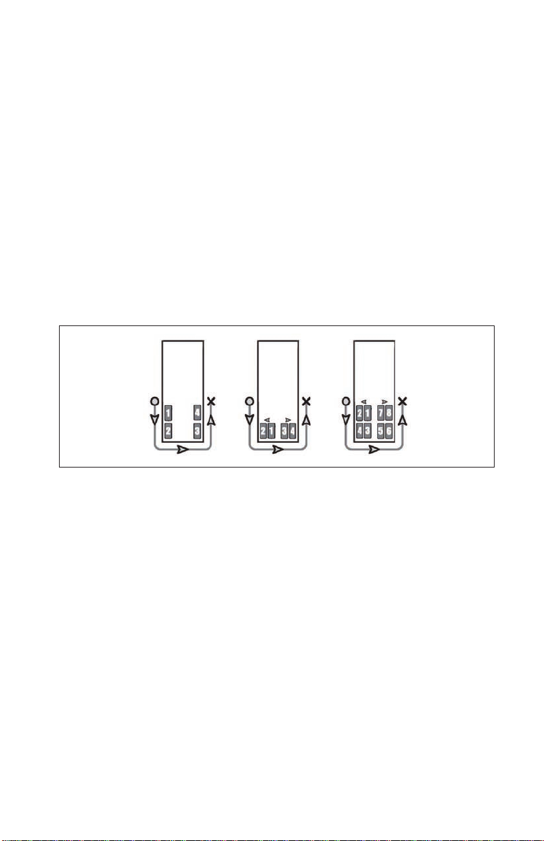
Figure 2

14
Section B - System Installation – Tire Sensors
3.0 System Installation: Tire Sensors
3.1 Sensor Overview
The SmarTire®TPMS sensor monitors tire pressure and temperature every
twelve (12) seconds and transmits tire data every three (3) to ve (5) minutes.
If a pressure change of 3 PSI is detected, the sensor will not wait for the next
regular transmission and will transmit tire data immediately. The sensor has
an estimated battery life of ve (5) years.
3.1.1 Break Away Cradle
If proper care is not taken when removing or installing a tire on a rim that
has a tire sensor installed, damage can occur. Each SmarTire tire sensor is
conveniently mounted in a break-away cradle so that if damage accidentally
occurs, the inexpensive cradle is broken instead of the sensor.
IMPORTANT NOTICE: PLEASE READ
Please read this section carefully and follow each step precisely to
ensure that you do not damage a sensor and that the sensors are
installed in the correct, pre-programmed locations.
SmarTire tire sensors can be broken when mounting and dismounting
a tire unless specic instructions are followed. If tire work is done
by an unauthorized facility, please let them know that a tire pressure
monitoring system is installed on the vehicle before they remove a tire
from a wheel.
Exercise caution and take precautions when cutting the steel strap
(See Section 3.3 step 2.). Beware of potential sharp edges!
Figure 3
3.2 Tools Required
Installing the Sensors
1. 5/16" or 8 mm hexagon driver
2. Metal cutter
3. Torque wrench

15
4. Tire changing equipment
5. Tire balancing equipment
3.3 Tire Sensor Installation
1. Remove the wheel from the vehicle and then remove the tire.
2. Wrap the strap around the rim in the lowest point of the drop center well
and mark it 1” (2.5 cm) past the worm gear. Cut the strap at the mark.
Excess strap MUST be removed or it will break-off and damage the tire.
3. Slide on the sensor.
1"
Figure 4
4. With the strap and sensor positioned in
the lowest point of the center well, feed
the end of the strap into the worm gear
and pull it tight. Orient the sensor so that
it is positioned at the valve with the worm
gear 4" (10 cm) away from the edge of
the sensor. The sensor MUST always
be installed at the valve in order to know
its approximate location after the tire has
been mounted. Figure 5
5. Tighten the strap using a 5/16" (8 mm) hexagon driver until the sensor
can not be moved. Reference torque: 35 in-lbs (4 Nm).
CAUTION: Do not over tighten the strap.
6. Indicate the location of the sensor by
applying the supplied rim label to a
clean and dry location on the rim.
Figure 6 - The actual
label design may vary

16
3.4 Re-mounting Tires After A Sensor Has Been Installed
Please read this section carefully and follow each step precisely toensureyou
do not damage the sensor when mounting the tire. If steps are not taken to
avoidthe sensor locatedin the drop center well of the rim,itcan be damaged
by tire beads as the tire is mounted.
3.4.1 Internal Tire Sensor Servicing
SmarTire®TPMStiresensors aredesigned tobe serviceableif damage occurs
duringthemounting or de-mounting process. Eachsensor is mounted inside
a break-away cradle that is designed to absorb the impact of damage during
the tire mounting / de-mounting process. If damage occurs, the inexpensive
cradle will break instead of the tire sensor.
If a sensor cradle is damaged, it along with the mounting strap must be
replaced. Carefullyremovethe tire sensorfromthedamaged cradle,re-insert
it into a new cradle (Bendix part number 264.00228N), and then continue
the mounting process.

17
3.4.2 Re-Mounting Tires Using Tire Irons
To avoid damaging the sensor, simply mount the tire ensuring that the last
part of the bead to slip over the ange happens directly at the sensor. Start
atoneendof thetireandwork towards the opposite end withthetire oriented
so that the beads are rst pushed under the rim ange directly opposite the
sensor (1) and then worked over the ange toward the sensor (2). The bead
will nally slip over the rim ange at the sensor without contacting it (3).
Repeat for the remaining bead.
12 3
Figure 7

18
3.4.3 Re-Mounting Commercial Tires
Using a Vertical Tire Machine
1. Place the rim on the machine so that the rim ange clamp is at the
12 o’clock position, the sensor is at the 2 o’clock position and the
mounting hook is at the 8 o’clock position.
Figure 8
RimFlangeClamp
Sensor
2. Advance the wheel clockwise to pass both beads over the rim ange
simultaneously.The tire should mountonto the wheel without contacting
the sensor.
Mounting
Hook
Figure 9
3.4.4 Re-Mounting Commercial Vehicle Tires
Using A Center Post Tire Machine
1. Place the rim on the machine with the mounting shoe at the 9 o’clock
position and the sensor at the 5 o’clock position.
Figure 10 Sensor
Mounting
Shoe

19
2. Place the tire on the rim with the bottom bead under the ange at the
6 o’clock position with the mounting shoe at the 9 o’clock position.
3. Advance the mounting shoe clockwise to pass the lower bead over the
rim ange.
4. Return the mounting shoe to the 9 o’clock position, depress the upper
bead under the rim ange at the 6 o’clock position and advance the
mounting shoe clockwise until the second bead is completely mounted.
3.4.5 Dual Wheel Assemblies
Inorder toaccommodateSmarTire®TPMS systemprogramming,dual wheels
MUST always be mounted on the vehicle with the valve stems 180° apart or
as close as possible to opposite each other.
Sensor
Sensor
Inboard TireOutboard Tire
Valve Stem
Valve Stem
Figure 11
3.4.6 Re-Mounting Light Truck Tires Using a Tire Machine
1. Placethe rimonthe turn-tableof a tiremounting machine withthe sensor
at the 7 o’clock position and the mount head at the 12 o’clock position.
2. Starting from the mount head, manually depress the bottom bead of the
lubricated tire on the rim and into the drop center well until its pinch point
is approximately 3” (7.5 cm) before the sensor.
(Note: The pinch point, also known as a “traction point” is the position
on the rim where the tire bead encounters resistance when trying to slip
over the rim ange.)
Figure 12

20
3. Advancethe turn-table clockwise using themount head to guidetherest
of the bottom bead over the ange and on to the rim. When assembled
correctly, the bead will slip over the ange without contacting the sensor.
4. Repeat for the top bead. Do not allow the pinch point to slip as the rim
rotates or the sensor could be broken.
5. Finish the tire installation as normal (seat the beads, install the valve
core, inate to the recommended cold ination pressure, balance tires
and mount wheels in specied locations).
3.5 Removing A Tire That Has A
SmarTire® TPMS Sensor Installed
This section outlines the correct methods for removing a tire from a wheel
that is equipped with a SmarTire®sensor. Instructions for using both tire
irons and a tire mounting machine are provided.
Please read these instructions carefully and follow each step precisely to
ensure you do not damage a sensor when dismounting the tire. If steps are
not taken to avoid the sensor located in the drop center well of the rim, it can
be crushed by the beads as the tire is removed.
3.5.1 Using Tire Irons
1. After removing the deated tire / wheel assembly from the vehicle, lay
the assembly on a oor mat and unseat both beads directly opposite
the sensor. The sensor should be located at the valve stem (the rim
mounteddecal shouldalso indicatethe sensor’slocation). Do notunseat
the bead at or near the sensor/valve stem.
Figure 13
2. Ensure that the mounting side of the wheel is facing upward and both
the bead and wheel ange are properly lubricated.
3. Starting near the sensor, lift the top bead over the wheel ange using tire
irons and progressively work away from the sensor until the top bead is
free. Be careful not to contact the sensor with the tire irons.
4. Again starting near the sensor, repeat the process for the bottom bead
until the tire is free from the wheel.
Table of contents


