SPX PEARPOINT P350 User manual

P350 flexitrax
Pearpoint’s advanced crawler-
based video inspection system
90/P350-OPMAN-ENG/05
Operation Manual lIssue 5 lJuly 2011

P350 flexitrax system
™

P350 exitrax Operation Manual i
Preface
Before you begin
Please read this operation manual before attempting to
use the P350 exitrax system. Note that this manual and
all its contents are subject to change. Pearpoint products
are under continuous development.
Pearpoint reserves the right to modify any product, including
this manual, without notice and some product changes may
have taken place after this user manual was published.
Contact your local Pearpoint dealer or visit
www.radiodetection.com for the latest information
about the P350 exitrax product family, including all
accessories, documentation and software updates.
Important safety notices
Please observe all safety notices and warnings in this manual
before operating any Radiodetection or Pearpoint product.
Warnings, Cautions and Notes
WARNING!: Warnings alert you to possible personal
injury.
CAUTION: Cautions alert you to possible equipment
damage.
NOTE: Notes contain useful information.
Key to symbols used
General Warning: Refer to Manual for specic
instruction or advice.
Electrical Hazard: Observe safe practices and
exercise extreme caution.
Heavy object: Additional care must be taken when lifting.
Biohazard: Disinfect after use. Wear appropriate
personal protective equipment (PPE).
Hot Surface: Allow to cool or use appropriate
protection when handling.
Pinch point: Keep ngers or loose clothing clear.
General
Pearpoint has taken care to provide the necessary
information in this manual for the safe installation,
operation, maintenance and disposal of this equipment.
However, a risk assessment should be performed prior
to commencing work as it may highlight additional safety
issues specic to the application.
Installation
The P350 exitrax, including its component parts is heavy.
If available, use the wheels to assist transport. Observe
heavy-lifting safety practices when lifting any component
of this system. Refer to the specications in Appendix 9.9
for a description of the system’s dimensions and weights.
If mains operated equipment is connected to the
system then the external equipment must be earthed in
accordance with the manufacturer’s instructions. Failure
to comply with this may cause the unit to become live and
a LETHAL HAZARD.
Generator Selection
Pearpoint strongly recommends the use of generator
equipment with Inverter type outputs. This results in the
best possible quality of supply voltage to the P350 system
over varying load conditions. To power the P350 system
in isolation (in all congurations) requires an inverter output
rated at 1.2kVA, additional electrical loads connected to
the same generator will increase the overall required rating
accordingly.
Generator equipment with AVR type outputs may be
suitable for use if the minimum requirements of generator
loading for AVR operation are met under all operational
circumstances; this is one reason why inverter output
equipment is highly recommended. The minimum load
the P350 system provides can be as low as 75VA. AVR
equipment operated below its minimum loading can lead
to loss of voltage regulation that could cause damage to
the P350 system. Additional high power loads (such as a
water heater or air-conditioner) on an AVR generator can
also lead to voltage uctuations that could exceed the
maximum ratings of the P350 system.
Generator equipment that does not employ voltage
regulation techniques outlined above (e.g. condenser
output or synchro-converter output) must not be used with
the P350 system as damage to the P350 system from
unregulated voltages is likely.
If in doubt regarding generator output selection, voltage
stability or installation of the generator into a vehicle, consult
a qualied electrician and/or your generator supplier.

ii P350 exitrax Operation Manual
Operation guidelines
Please observe your company, region or country’s
Standard Code of Practice for surveying underground
utilities with CCTV equipment, if applicable, when using
this equipment.
Always carry out a risk assessment of the site to be
inspected. This equipment is NOT approved for use in
areas where hazardous gasses may be present.
Foul water systems can be a source of serious
biological hazards. Wear appropriate protection when
handling the P350 exitrax.
The camera will get hot during use. This is normal.
Exercise care when handling the camera at all times.
System components must NOT be connected/
disconnected when the power is on.
Take care to ensure that video and power cables do not
get entangled in the drum. Cables ties are recommended
and will not impede system performance.
Always store the P350 exitrax system in a clean and dry
environment.
Safety precautions
Ensure that standard safety precautions for working in
hostile environments are followed.
The exitrax Power Supply Unit (PSU) is designed to
reduce hazards from electric shock provided that proper
operating procedures are followed. The P350 exitrax
system requires connection to a protective earth; if in
doubt, consult a qualied electrician.
Electrical equipment is factory tested for electrical safety.
Routine inspection is recommended (and may be required
by law) to maintain this level of protection. If you are
unsure, contact your local safety authority for advice.
The exitrax Power Supply Unit has a number of
ventilation slots around the casing that are designed
to maximize air circulation and reduce heat. There is a
potential re risk if the build-up of heat is prevented from
escaping. Under no circumstances are these ventilation
slots to be covered or blocked.
If using a generator follow the manufacturer’s instructions
on load connection and sequencing. In the absence of
these instructions the following guidelines should be used:
When starting the generator; ensure that all electrical
loads, including the P350 are switched off before
starting the generator. Allow the generator to
stabilise before connecting any electrical loads or
switching on the P350.
•
When stopping the generator; ensure all electrical
loads, including the P350 are switched off before
stopping the generator.
Starting or stopping a generator whilst the P350
system is connected and the main switch is in the
On position could lead to damage to the P350
system or the generator.
Always use heavy duty industrial gloves when handling
cable which is being withdrawn from a sewer.
Always ensure that cabling is properly connected.
A portable generator can be a hazard if not properly
operated. Always follow the manufacturer’s instructions.
Always transport a generator with the minimum amount of
fuel in the tank.
Always switch the system on and off using the main
system switch.
Never lower crawlers or other heavy equipment into
manholes while personnel are working in the manhole.
To avoid risk of burns do not touch cameras/
lightheads when they are switched on or immediately
after switch off. Leave ample time for them to cool before
handling.
The camera’s LEDs are very powerful. Do not look
directly at the LEDs or point them at other people.
Maintenance
Clean and sanitize the P350 exitrax system at regular
intervals and after conducting an inspection.
Always keep all connectors covered with their protective
caps when the equipment is not in use.
Do not dismantle any component of this system
unless directed by this operation manual. Dismantling
components not specied by this manual may void the
product warranty.
Pearpoint recommends that only authorized service
centers carry out service of this product. Service
elsewhere will void the warranty.
For information regarding any service needs, please
visit www.radiodetection.com or contact your local
Radiodetection or Pearpoint representative or dealer.
Disposal
Do not dispose of this product in municipal waste
facilities. Please check local regulations for disposal of
electronic products.
Radiodetection complies with the requirements of
2002/96/EC Waste Electrical and Electronic Equipment.
•
•

P350 exitrax Operation Manual iii

iv P350 exitrax Operation Manual
Compliance
EU Compliance
This equipment complies with the following EU Directives.
Low Voltage Directive: 2006/95/EC
Machinery Directive: 98/37/EC
EMC Directive: 2004/108/EC
R&TTE Directive: 99/5/EC
FCC Compliance Statement
This equipment complies with Part 15 of the FCC Rules.
Operation is subject to the following two conditions:
The equipment may not cause harmful interference.
The equipment must accept any interference
received, including interference that may cause
undesired operation.
Note: This equipment has been tested and found
to comply with the limits for a Class A digital device
pursuant to Part 15 of the FCC Rules. These limits are
designed to provide reasonable protection against
harmful interference when the equipment is operated in
a commercial environment. This equipment generates,
uses, and can radiate radio frequency energy and,
if not installed and used in accordance with the
manufacturer’s instruction manual, may cause harmful
interference with radio communications. Operation of
this equipment in a residential area is likely to cause
harmful interference, in which case you will be required
to correct the interference at your own expense.
Modications: Any modications made to this equipment
that are not approved by Pearpoint may void the authority
granted to the user by the FCC to operate this equipment.
Industry Canada compliance
statements
ICES-003 Class A Notice:
This Class A digital apparatus complies with Canadian
ICES-003.
Avis NMB-003, Classe A:
Cet appareil numérique de la classe A est conforme à la
norme NMB-003 du Canada.
Bluetooth transmitter
Contains Transmitter Module FCC ID: PI409B / IC:
1931B-BISMPA33.
•
•
•
•
•
•
Trademarks
exitrax, exiprobe, FlexiSight and RD7000DL are
trademarks of Radiodetection Ltd, all rights reserved.
Pearpoint is a trademark owned by Radiodetection Ltd
- SPX Corporation.
The Bluetooth word, mark and logo are registered
trademarks of Bluetooth SIG, Inc. and any use of such
trademarks by Radiodetection is under license.
Windows, Windows XP, Windows Vista, Windows
Media Player, Windows Movie Maker, Microsoft Word
and Microsoft Ofce 97 are trademarks of Microsoft
Corporation, all rights reserved.
QuickTime, Mac, Mac OS, Finder, iMovie and Final Cut
Pro are trademarks of Apple Inc., registered in the U.S
and other countries.
Other trademarks or registered trademarks mentioned in
this document belong to their respective owners.
Disclaimer
Any third-party products (including hardware, software
and services) mentioned in this manual are for
instructional purposes only and is not an endorsement by
Radiodetection Ltd, Pearpoint and SPX Corporation.
Radiodetection Ltd does not accept any liability for loss of
data or damage to equipment when using any third-party
products.
Copyright statement
Copyright 2011 Pearpoint Ltd. / Radiodetection Ltd
– SPX Corporation. All rights reserved.
Radiodetection is a subsidiary of SPX Corporation.
SPX, Radiodetection and exitrax are trademarks of
Radiodetection Ltd. and SPX Corporation. Due to a policy
of continued development, we reserve the right to alter or
amend any published specication without notice.
This document may not be copied, reproduced,
transmitted, modied or used, in whole or in part, without
the prior written consent of Radiodetection Ltd.
Training
Pearpoint provides training services for most Pearpoint
products. Our qualied instructors will train equipment
operators or other personnel at your preferred location
or at Pearpoint headquarters.
For more information go to www.radiodetection.com
or contact your local Pearpoint representative.

P350 exitrax Operation Manual v
Table of contents
Preface i
Before you begin i
Important safety notices i
Warnings, Cautions and Notes i
Key to symbols used i
General i
Installation i
Operation guidelines i
Safety precautions i
Maintenance ii
Disposal ii
Compliance iv
EU Compliance iv
FCC Compliance Statement iv
Industry Canada compliance statements iv
Bluetooth transmitter iv
Trademarks iv
Disclaimer iv
Copyright statement iv
Training iv
Section 1 – Introduction 1
1.1 About this manual 1
1.2 Overview 1
1.3 Safety notices 1
1.4 Latest updates and information 1
Section 2 – System overview 2
2.1 Command module 2
2.1.1 Keypad 2
2.2 Cable drums 4
2.2.1 Powered drum 4
2.2.2 Manual drum 4
2.2.3 External PSU (manual system only) 4
2.2.4 Link cables 4
2.3 Crawlers and Crawler cameras 6
2.4 Pushrod reels and cameras 6
2.5 Accessories 6
Section 3 – System assembly 7
3.1 Crawler and accessories 7
3.1.1 Crawler weight (P354 Only) 7
3.1.2 Wheels and tires 8
3.1.3 Cameras 10
3.1.4 Elevator 10
3.1.5 Auxiliary Lighthead 11
3.1.6 Crawler connection 12
3.2 Crawler deployment tools 12
3.3 Manual drum and external PSU 13
3.4 Powered drum 13
3.5 Command module 13
3.5.1 Mounting 13
3.5.2 Power, data and video 13
3.5.3 Compact Flash card 13
3.5.4 Keyboard 13
3.5.5 Headset 13
3.6 External video equipment 13
Section 4 – Command module
and system setup 14
4.1 Overview 14
4.2 Powering up 14
4.3 Getting help 14
4.4 Welcome screen 14
4.5 On-screen display (OSD) 15
4.5.1 Customizing the OSD 15
4.5.2 OSD layouts 15
4.5.3 System menu timeout 16
4.5.4 Text appearance 17
4.6 System Menu 17
4.6.1 General navigation and text entry 17
4.6.2 SETUP menu 18
4.6.3 CARD menu 20
4.6.4 DVR menu 20
4.6.5 SCRN menu 22
4.6.6 DRIVE 22
4.6.7 TEXT and Report menu 23
4.7 Command module settings 24
4.8 Drum and reel settings 24
4.8.1 Drum type and cable length 24
4.9 Crawler and camera settings 24
4.9.1 Crawler wheel size 24
4.9.2 Numeric inclinometer 24
4.9.3 Camera settings 25
4.10 Company details 25
4.11 Splash and video title screens 26
4.11.1 Splash screens 26
4.11.2 Video title screen 26
4.12 Ethernet conguration 26
4.13 Restoring factory settings 27

vi P350 exitrax Operation Manual
Section 5 – System operation 28
5.1 Emergency stop 28
5.2 Deployment 28
5.2.1 Before deployment 28
5.2.2 Using the crawler deployment tool 28
5.2.3 Cable and manhole rollers 30
5.2.4 Distance counter and Auto Stop point 31
5.2.5 Sonde 31
5.3 Driving crawlers 31
5.3.1 System stop 31
5.3.2 Drive mode and OSD 31
5.3.3 Mimic 33
5.3.4 Navigating with advanced mimic 34
5.3.5 Pitch proler 34
5.3.6 Manual system 36
5.3.7 Powered drum 36
5.3.8 Steering (P356 crawler only) 37
5.3.9 Tractor power 38
5.4 Video recording 38
5.5 Still pictures 38
5.6 Camera controls 38
5.6.1 Lights 38
5.6.2 Auxiliary lighthead 38
5.6.3 Focus 39
5.6.4 Pan 39
5.6.5 Tilt or rotate. 39
5.6.6 Center 39
5.6.7 Zoom 39
5.7 Digital image controls 39
5.7.1 Pan 39
5.7.2 Rotate 39
5.7.3 Zoom 39
5.8 Pendant controller 40
5.9 Retrieving the crawler 43
Section 6 – File management and Transfer 44
6.1 CARD menu 44
6.1.1 Destination folder 44
6.1.2 Reports 45
6.1.3 Card status 45
6.1.4 Formatting the card 45
6.2 Supported card types 45
6.3 File browser 46
6.3.1 Organizing your work 46
6.3.2 Filename structure 46
6.3.3 Copying les 46
6.3.4 Moving les and folders 47
6.3.5 Renaming les and folders 47
6.3.6 Deleting les and folders 47
6.3.7 Creating folders 47
6.3.8 Sending a le with Bluetooth®: 47
6.3.9 Information 47
6.4 Viewing Pitch Log 47
6.5 Viewing JPEG pictures 48
6.6 Playing videos 48
6.6.1 Screen captures 49
6.7 USB connections 49
6.6.1 Disconnecting 49
6.8 Bluetooth®50
6.8.1 Pairing 50
6.8.2 Transferring les 50
Section 7 – Inspection reports
and text pages 52
7.1 About reports and pages 52
7.2 Defect Codes 52
7.3 Video text pages 52
7.3.1 Browsing text pages 52
7.3.2 Overlay selected page 52
7.3.3 Remove text page 52
7.3.4 Editing text pages 52
7.3.5 Changing text appearance 53
7.4 Reports 53
7.4.1 Creating a new report 54
7.4.2 Client 54
7.4.3 Company 54
7.4.4 Freetext 55
7.4.5 Observations 55
7.4.6 Photos 55
7.4.7 Site page 56
7.4.8 Survey 56
7.5 Editing reports 56
7.6 Deleting reports 57
7.7 Viewing and printing reports 57
7.7.1 Folder structure 57
7.7.2 Browsing and printing 57
7.8 Exporting reports to Word 58
7.8.1 Conversion requirements 58
7.8.2 Conversion overview 58
7.8.3 Conversion troubleshooting 59
7.8.4 Customizing the Word template 59
Section 8 – Digital Video 60
8.1 Video Specication 60
8.2 Video quality Settings 60
8.2.1 Custom quality settings 61
8.3 Advanced video options 61

P350 exitrax Operation Manual vii
8.3.1 INPUT 61
8.3.2 DESTN 62
8.3.3 FNAME 62
8.4 Video playback 62
8.4.1 Command module playback 62
8.4.2 Computer playback 62
8.5 Distributing your recordings 63
8.5.1 Producing a DVD video 64
8.5.2 Supported digital video les 64
8.5.3 Unsupported digital video les 65
8.5.4 Using data CDs, DVDs and USB ash drives 65
8.6 Converting digital videos 66
8.6.1 System requirements 66
8.6.2 Conversion software for Windows 66
8.6.3 Conversion software for Mac OS X 66
8.7 Advanced video editing 67
8.7.1 FlexiSight 67
8.7.2 DV 67
Section 9 – Appendix 68
9.1 Shortcuts 68
9.2 Care and maintenance 69
9.2.1 Terminals 69
9.2.2 Cleaning the system 69
9.2.3 Storing the system 69
9.3 Upgrading software 69
9.4 Crawler cable re-termination 71
9.5 Cable drum replacement 72
9.5.1 Disassembly 72
9.5.2 Assembly 73
9.5.3 Replacing cable 73
9.6 AVC Video licence 74
9.7 Defect codes text le 74
9.7.1 Text encoding 74
9.8 Specications 75
9.8.1 Environmental specications 75
9.8.2 Command module 75
9.8.3 Cable Drums 76
9.8.4 Crawlers 76
9.8.5 Cameras 76
9.8.6 Auxiliary lighthead 77
9.8.7 Elevators 77
9.8.8 Pendant Controller 77
9.8.9 Approvals 77
List of figures and tables
Figure 2.1: Command module 3
Figure 2.2: Command module rear view 3
Figure 2.3: Command module I/O panel 3
Figure 2.4: Command module keypad 3
Figure 2.5: Powered drum with command module
installed 5
Figure 2.6: Manual drum 5
Figure 2.7: Front and rear connection panels
(Common to powered drum and external PSU) 5
Figure 2.8: External PSU 5
Figure 2.9: Link cables 5
Figure 2.10: P354 crawler with P350-CAM-FW
camera installed 6
Figure 2.11: P356 crawler with P350-CAM-PTZ
camera installed 6
Figure 3.1: P356 crawler assembly 7
Figure 3.2: Connecting various tires 8
Figure 3.3: Crawler congurations (opposite) 8
Figure 3.4: Connecting a xed view camera 10
Figure 3.5: Fixed view camera 10
Figure 3.6: Pan and tilt camera 10
Figure 3.7: Pan, tilt and zoom camera 10
Figure 3.8: P350 camera elevators 11
Figure 3.9: Adjustable elevator 11
Figure 3.10: Installing the large adjustable elevator 11
Figure 3.11: Adjusting the large adjustable elevator 11
Figure 3.12: Auxiliary lighthead 11
Figure 3.13: Strain relief clamp and spring guard 12
Figure 4.1: Welcome Screen 14
Figure 4.2 System onscreen display (OSD) 15
Figure 4.3: Normal OSD layout 16
Figure 4.4: TV OSD layout 16
Figure 4.5: Custom OSD layout 16
Figure 4.6: Main screen showing top-level
system menu 17
Table 4.1: Setup menu schema. 18
Table 4.2: CARD menu schema 20
Table 4.3: DVR menu schema 21
Table 4.4 Screen menu schema 22
Table 4.5: Drive menu schema 22
Table 4.6: TEXT menu schema 23
Figure 4.7 Company information menu 25
Figure 4.8: Video title page 26
Figure 4.9: Ethernet conguration 27
Figure 5.1: Downhole cable rollers 28
Figure 5.2: Crawler grab kit 28

viii P350 exitrax Operation Manual
Figure 5.3: Crawler grab setup 29
Figure 5.4: Crawler grab and crawler 29
Figure 5.5: Crawler grab and crawler
with attached elevator 30
Figure 5.6: Crawler grab in the closed position 30
Figure 5.7: Lowering the crawler into a manhole 30
Figure 5.8: Using cable rollers 30
Figure 5.9: Driving mode OSD 32
Figure 5.10: Basic mimic 33
Figure 5.11: Steering mimic 33
Figure 5.12: Pan and tilt mimic with steering bar 33
Table 5.1: Advanced mimic controls 34
Figure 5.13: Advanced mimic controls 35
Figure 5.14: Crank handle for powered drum 37
Figure 5.15: Pendant controller 40
Figure 6.1 Compact Flash card warning page 44
Figure 6.2: CARD menu 44
Figure 6.3: Compact Flash card status page 45
Figure 6.4: Compact Flash browser 46
Figure 6.5: File browser delete and show screen 47
Figure 6.6: Windows USB hub manager 49
Figure 6.7: Bluetooth® menu 50
Figure 6.8: Bluetooth® device selection page 51
Figure 6.9: Mac OS X Sharing preferences 51
Figure 7.1: Text and Report menu 52
Figure 7.2 Video text editing page 53
Figure 7.3: Report menu 53
Figure 7.4: Report pages 54
Figure 7.5: Viewing reports in Internet Explorer 57
Figure 7.6: Report Navigation 58
Figure 7.7: FlexiSight Report select box 58
Table 8.1: Video Quality proles 60
Figure 8.1: DVR Record settings menu 60
Figure 8.2: Advanced video settings menu 60
Figure 8.3: Video playback on Windows XP
using VLC media player 63
Figure 8.4: 4:3 aspect ratio video space usage 63
Table 9.1: Miscellaneous commands and shortcuts 68
Table 9.2: Crawler commands and shortcuts 68
Table 9.3: Camera commands and shortcuts 68
Table 9.4: Video commands and shortcuts 69
Figure 9.1: Software Versions info page 69
Figure 9.2: Camera info page 70
Figure 9.3: Crawler info page 70
Figure 9.4: Drum info page 71
Figure 9.5: Command module info page 71
Figure 9.6: Drum cassette replacement (exploded) 72
Figure 9.7: Powered drum with slave side panel
and drum support channel removed 72
Figure 9.8: Adjusting the drive train 73
Figure 9.9: Cable layering sprocket and follower 73
Figure 9.10: Cable layering mechanism 73
Figure 9.11: Cable drum cassette 73
Table 9.6: Defect_codes.txt structure 74

P350 exitrax Operation Manual 1
Section 1 – Introduction
1.1 About this manual
This manual provides comprehensive operating
instructions for the P350 exitrax™ pipeline video
inspection system. Before attempting to operate the
P350 exitrax system it is very important that you read
this manual, noting all safety warnings and procedures
in the Preface, Section 1.3 and throughout the rest of
the manual.
Once you have read this manual, it is recommended that
you retain it for reference purposes. A printed version of
this manual is available on request. Please contact your
local Pearpoint representative for more information. The
rest of the manual is detailed as follows.
Section 2 includes annotated illustrations of the command
module, powered and manual drums and selected
accessories.
Section 3 provides a detailed guide to assembling the
system ready for conducting inspections.
Section 4 provides a comprehensive introduction to using
and conguring the command module.
Section 5 introduces the basics of pipeline inspections
and describes how to deploy and drive the crawler,
create video recordings and control the camera during
an inspection. Section 5 also details retrieving the crawler
safely once the inspection is concluded.
Section 6 introduces the Compact Flash card browser and
provides a detailed guide to managing your survey les.
Section 7 introduces the report writing function and
shows you how to view reports or convert them to
Microsoft Word format. Section 7 also details the ability to
edit and display system text pages.
Section 8 provides a comprehensive guide to digital video
options and settings. Section 8 also includes a guide
to converting and distributing videos for playback on
computers and other video equipment.
Section 9 is an appendix that includes reference and
other important information as well as instructions on
caring for and maintaining your P350 system.
1.2 Overview
The P350 exitrax is an advanced pipeline video
inspection system that is ideal for a broad range of
applications. This system allows operators to identify and
document pipeline faults using the latest in digital video
recording technology.
The P350 exitrax is a fully modular system; the
command module can drive any combination of drums,
cameras and crawlers and is also compatible with the
P330+ and P340 exiprobe™ range of pushrod reels and
cameras.
1.3 Safety notices
Caution must be taken when conducting any pipeline
or draining system inspection. Please observe all safety
warnings located in the Preface and throughout this
operation manual.
Before you attempt to operate the P350 exitrax
system, it is recommended that you familiarize yourself
with any additional health and safety requirements that
may be dened by company policy and any applicable
local or national laws. Contact your company’s or
local government’s health and safety ofcer for further
information.
1.4 Latest updates and information
Pearpoint may have released new system software, user
documentation or other information after you purchased
your system.
You can download the latest software, documentation
and application notes from www.radiodetection.com.
For more information about checking and upgrading your
system’s software, please refer to Appendix 9.3.

2 P350 exitrax Operation Manual
Section 2 – System overview
RJ-45 socket: Connects to a PC running
compatible reporting software.
Optional Vehicle wall mount kit: to mount the
command module to the side of your van
(not shown).
2.1.1 Keypad
Function keys: Use to select menu items or
activate shortcuts.
Camera key: Press to take screen captures.
Text key: Press to access the Text and Report
menu.
Play: Enters the card browser menu. Starts video
playback of selected le.
Pause: Press to pause video playback or
recording.
Record: Press to begin a new video recording.
Stop: Press to stop video playback or recording.
Crawler stop: Stops the crawler moving.
Arrow keys: Use for navigation and to select
system parameters.
OK: Press to select or conrm choices in the
menu system.
LED Brightness/Camera Focus keys: Adjust LED
brightness and camera focus. Fn + brightness key
to adjust camera focus.
Rotate/Pan keys: Press to rotate the camera view.
Fn + Rotate to pan left or right. Simultaneous
press will re-center the view.
Zoom/Iris keys: Press to zoom in or out of the
camera’s subject. Fn + Zoom to modify the Iris.
Simultaneous press will reset the zoom to unity,
Fn + simultaneous press will reset to automatic
iris.
Function key (Fn): Press and hold to activate
different functions.
15.
16.
17.
18.
19.
20.
21.
22.
23.
24.
25.
26.
27.
28.
29.
30.
2.1 Command module
The command module acts as the controller and digital
video recorder and playback device. Video is displayed
on an 8” industrial LCD. Video, pictures and inspection
reports are stored on a compatible high-speed Compact
Flash card.
On/Off Switch: This switch only works when the
unit is powered by a DC source connected to the
power socket.
Keypad and function keys: Allows the operator to
control the system, select functions and edit text
entries.
Keyboard: Provides enhanced text entry
capabilities and shortcuts to access system
functions.
Display: LCD Screen shows video, images and
various on-screen system information.
Link Cable Socket: To connect the pushrod reel,
powered drum or manual external PSU to the
command module with a link cable.
Command module support clamp: To mount the
command module to the powered or manual
drum support stand or to the optional vehicle wall
mounting kit.
Fuse holder: 5x20mm T3.15A 250V cartridge
fuse.
RCA Video Jacks: Provide secondary input and
output options for external composite video
equipment.
Power Socket: DC power input from vehicle
supply, battery box or mains adapter. For use with
pushrod reels or as a standalone unit.
Compact Flash card slot: The command module
uses a Compact Flash card to store video
recordings, reports and pictures. Most stored
les can be viewed or played on the command
module or transferred to PC. Also used to store
and upload software upgrades.
Keyboard Socket: Connects the keyboard.
Audio Socket: Connects the optional headset to
record audio over videos.
USB-A socket: Reserved for future use.
USB-B socket. USB connection to transfer les to
computers.
1.
2.
3.
4.
5.
6.
7.
8.
9.
10.
11.
12.
13.
14.

P350 exitrax Operation Manual 3
2
4
1
12
11
7
8
15
9
10
13
14
Figure 2.1: Command module Figure 2.3: Command module I/O panel
Figure 2.4: Command module keypad
5
Figure 2.2: Command module rear view
17
18
20
22
23 24
26
25
30
27
28
29
19
21
6
3

4 P350 exitrax Operation Manual
2.2 Cable drums
The system supports either a powered or manual drum
that can accommodate cable lengths of 100m (330’),
150m (495’) or 250m (820’). The powered drum contains
an integral power supply whilst the manual drum requires
an external power supply unit.
The cable drum cassette in the powered drum is
user-replaceable. Please refer to Appendix 9.5 for
instructions on how to remove and install the cable
drum cassette.
Optional lengths of cable are also available for both the
powered and manual drums. Please refer to Appendix 9.5
for instructions on how to remove and install the cable.
Please visit www.radiodetection.com for a complete list
of spares and accessories.
2.2.1 Powered drum
Command module support stand.
On/Off switch. Switches the system on or off.
Command module.
Reel compartment: Houses up to 250m (820’) of
cable wound onto the drum cassette.
Removable handle, handle bars and wheels:
Allow you to manoeuvre the system easily into
position.
Emergency stop: Instantly shuts off system
power. When initiated, the system must be reset.
Pendant connector: For connecting the optional
pendant controller.
Command module connector: To connect the
command module link cable.
BNC Video Jacks: Provide secondary input and
output options for external composite video
equipment.
Power supply socket: To connect mains power.
Fuse holder: 5x20mm T12A 250V cartridge fuse.
Crank handle: Will allow the manual retrieval of
the deployed cable. (Not shown).
Optional vehicle mounting rails: To secure the
system in your van. (Not shown).
Cable rollers.
1.
2.
3.
4.
5.
6.
7.
8.
9.
10.
11.
12.
13.
14.
2.2.2 Manual drum
Cable drum: Houses up to 250m (820’) of cable.
Cable brake.
Crawler connection terminal (Not shown).
Crank handle socket.
Command module support clamp.
PSU link cable socket.
Manual layering handle: To assist with laying cable
evenly on the drum.
Cable rollers.
2.2.3 External PSU (manual system only)
On/Off switch. Switches the system on or off.
Emergency stop: Instantly shuts down the system
power. When initiated, the system must be reset.
Pendant connector: To connect the optional
pendant controller.
Command module connector: To connect the
command module link cable.
BNC Video Jacks: Provide secondary input and
output options for external composite video
equipment.
Power supply socket: To connect mains power.
Fuse holder: 5x20mm T12A 250V cartridge fuse.
Link cable connection for manual drum.
2.2.4 Link cables
Command module link cable.
Manual drum link cable.
15.
16.
17.
18.
19.
20.
21.
22.
2.
6.
7.
8.
9.
10.
11.
23.
24.
25.

P350 exitrax Operation Manual 5
Figure 2.5: Powered drum with command module installed
1
4
5
3
Figure 2.7: Front and rear connection panels (Common to powered
drum and external PSU)
8
9
10
2
11
7
6
Figure 2.8: External PSU
23
Figure 2.6: Manual drum
20
16
15
19
18
Figure 2.9: Link cables
24
25
22 22
14
21

6 P350 exitrax Operation Manual
2.3 Crawlers and Crawler cameras
The system offers two different crawlers: the P354
(100mm/4”) and P356 (150mm/6”). Both crawlers are
fully compatible with three interchangeable cameras.
The P350-CAM-FW is a xed, forward view camera. The
P350-CAM-PT offers pan and tilt capabilities and the
P350-CAM-PTZ offers pan, tilt and 10x optical zoom.
2.4 Pushrod reels and cameras
The command module is compatible with the full range
of P330+ and P340 exiprobe pushrod reels, cameras
and accessories. When used with a pushrod system,
the command module must be connected directly to
the pushrod coiler. Power is supplied by mains or a
vehicle adapter, which connects to the DC socket in the
command module’s I/O panel. When a pushrod system is
connected, the command module’s power switch will turn
the system on and off.
Refer to 4.8.1 for information on how to congure the
command module to drive a pushrod system
For information on assembling and using a pushrod
system, refer to the P330+ and P340 exiprobe user
documentation available on the FlexiSight installation CD
or at www.radiodetection.com.
2.5 Accessories
The P350 exitrax system features a range of accessories
that expand its functionality and range of applications.
Please visit www.radiodetection.com, for a complete list
of available accessories.
Figure 2.10: P354 crawler with P350-CAM-FW camera installed
Figure 2.11: P356 crawler with P350-CAM-PTZ camera installed
P350 exitrax Operation Manual 7
Section 3 – System assembly
The P350 exitrax allows you to congure the
system in a large number of ways, depending on the
components you have chosen for your survey. This
section provides details on assembling and setting up
a system using either the powered or manual drum
and external PSU.
WARNING! Before attempting to assemble the
system, ensure that the powered drum or the manual
PSU is switched off.
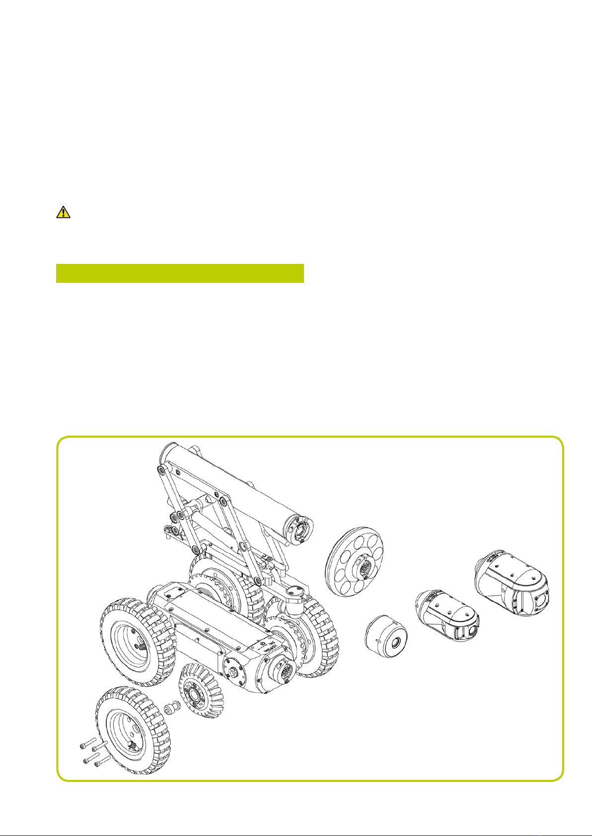
3.1 Crawler and accessories
You can congure the P354 and P356 crawlers with a
variety of wheels, tires, cameras and accessories to suit a
wide range of pipes and conduits.
Figure 3.1 demonstrates the modularity of the crawlers.
It shows an exploded view of some of the many
congurations available.
3.1.1 Crawler weight (P354 Only)
The crawler weight is a metal plate designed to increase
traction on the P354 crawler by adding more weight to
the crawler’s body.
To x this to the body, place the weight on the crawler’s
body before adding any other components or accessories
and x in place using the supplied screws.
Figure 3.1: P356 crawler assembly
8 P350 exitrax Operation Manual
3.1.2 Wheels and tires
The P354 is compatible with the 62mm (2.5”) and 110mm
(4.3”) wheel sets, which can be connected in singular
or twin congurations. This conguration allows you to
deploy the P354 in pipes from 110mm (4”) up to 380mm
(15”) in diameter.
The P356 is compatible with the 62mm (2.5”), 110mm
(4.3”) and 170mm (6.7”) wheels, which can be connected
in singular or tandem congurations. This conguration
allows you to deploy the P356 in pipes from 150mm (6”)
to 610mm (24”) in diameter.
The 62 and 110mm wheel sets are compatible with a
hard or soft tire set to suit most traction requirements.
Figure 3.2: Connecting various tires
Figure 3.3: Crawler configurations (opposite)
For a complete list of compatible wheels and tires, please
visit www.radiodetection.com.
Figure 3.3 (opposite) shows a range of recommended
wheel and elevator congurations to suit a variety of
pipe diameters and to position the chosen camera in the
center of the pipe.
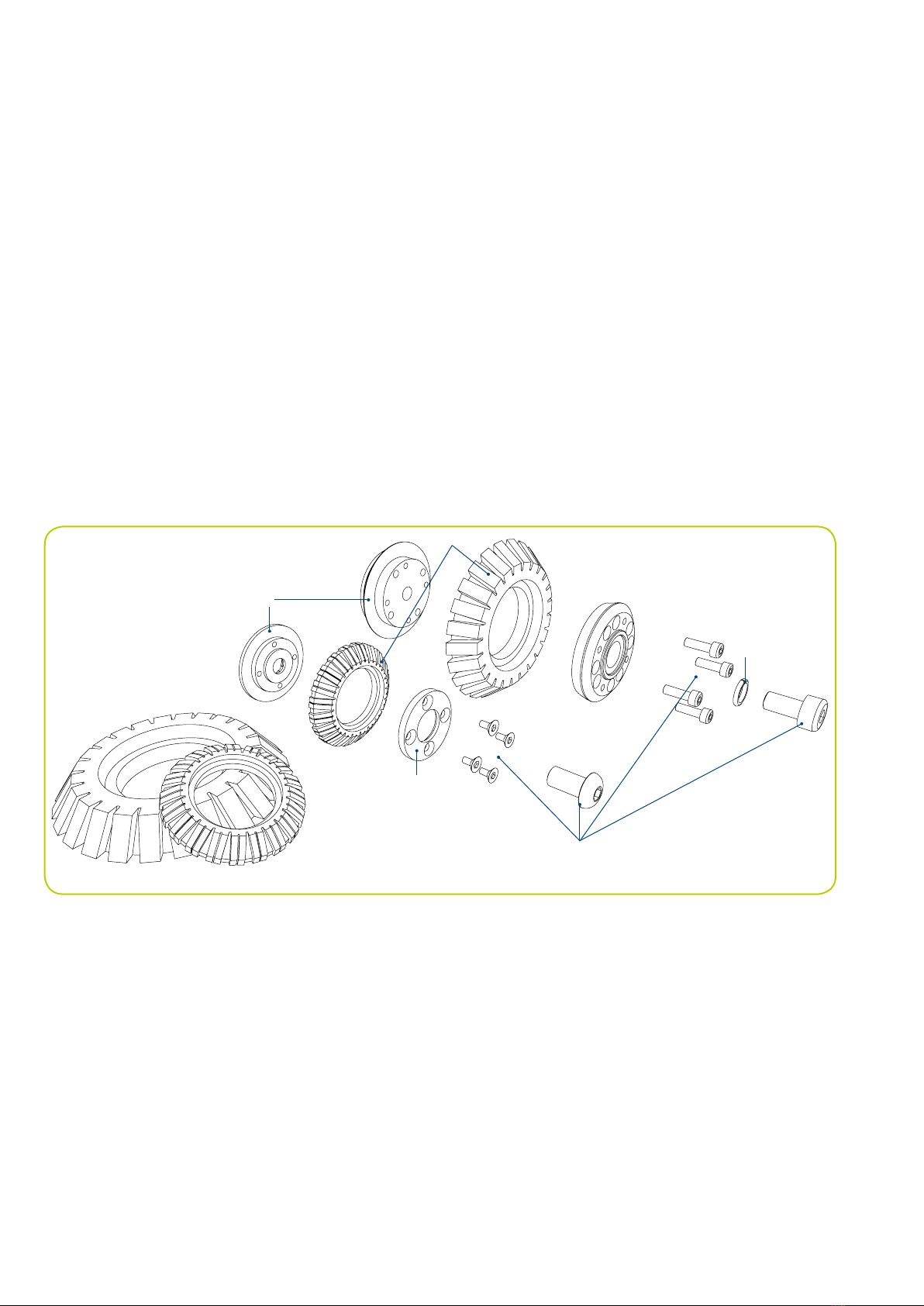
Connecting wheels and tires
Figure 3.2 demonstrates how to attach wheels and tires
to the P354 and P356 crawlers (62mm and 110mm only).
The inner hub is located on the crawler’s body. Place the
wheel on the inner hub and secure in place using the
outer hub clamp.
NOTE: Make sure you afx the wheel screws rmly to
the crawler body.
5
1 Inner hub
2 Wheel or tire
3 Outer hub clamp
4 Fasteners
5 Washer
3
2
1
4

P350 exitrax Operation Manual 9

10 P350 exitrax Operation Manual
3.1.3 Cameras
The P354 and P356 are compatible with three high-
resolution cameras that support PAL or NTSC video
standards.
All cameras offer remote focus capabilities and use the
latest generation of ultra bright LEDs for optimum light
performance.
Cameras can be tted direct to the crawler’s body or to
an elevator or lighthead if used. The cameras are simple
to attach as they can only be tted in one way. A single
3mm Allen-head screw is used to secure the camera’s
collar to the crawler’s body, lighthead or elevator.
Connecting cameras
Figure 3.4 illustrates the connection of cameras using the
C-clamp connection. Note that the procedure is the same
for all supported cameras.
Figure 3.4: Connecting a fixed view camera
Supported cameras:
Fixed View camera
P350-CAM-FW (Figure 3.5): this robust and compact
camera offers a focal range from 10mm to innity and a
120 lm light source.
Figure 3.5: Fixed view camera
Pan and Tilt cameras
P350-CAM-PT (Figure 3.6): the pan and tilt capabilities
provides the crawler with almost 360° vision. The pan
and tilt camera’s focal range is from 10mm to innity; it
features a 210 lm light source.
Figure 3.6: Pan and tilt camera
P350-CAM-PTZ (Figure 3.7): this camera has the same
pan and tilt features as the P350-CAM-PT camera. The
PTZ camera also features auto focus, 10x optical zoom
with a focal range of 10mm (WIDE) to innity and a 420 lm
light source.
Figure 3.7: Pan, tilt and zoom camera
3.1.4 Elevator
The P350 elevators are used to elevate the camera and
help center it in pipes 254mm (10”) in diameter or larger,
see Figure 3.3. The elevator is installed between the
crawler and camera.
The P350 system offers a choice of 3 elevators:
P350-ELV-F xed elevator (Figure 3.8 left). The xed
elevator will deploy the P354 in pipes up to 300mm
(12") and the P356 in pipes up to 380mm (15”).
P350-ELV-A adjustable elevator (Figure 3.8 center).
The adjustable elevator will deploy the P354 in pipes
up to 350mm (15") and the P356 in pipes up to
458mm (18").
•
•
Other manuals for PEARPOINT P350
1
Table of contents


