7/36Updated: Dec. 23, 2020
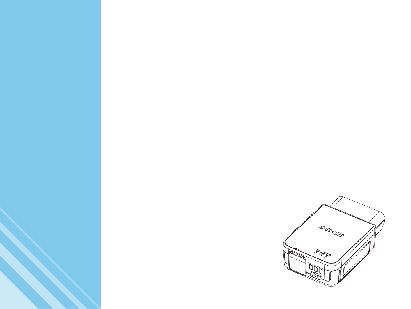
Product specifications
Item Specifications
MATSU TAKE UME
CPU 32-bit microcomputer
External interface *1
PC
communication
USB USB2.0 x 1 (Mini-DIN connector)
Wireless LAN IEEE802.11abgn
Bluetooth IEEE802.15.1 Ver.4.0/Class1
SD memory card
(supporting SD and SDHC memory cards) Slot x 1 - -
Vehicle
communication
ISO9141(K/L) 〇 〇 〇
HS-CAN 〇 〇 〇
ISO13400
(Ethernet) 〇- -
* Contact the distributor about other inquires related to communicationwith the vehicle.
Main unit power
supply voltage Vehicle power supply DC6.5 ~32V
USB power (BUS power) DC4.75 ~5.25V *2
Power consumption MAX. 2.5W(12VDC)
Operating
environment
Operating temperature
[Storage temperature]-10 ~50℃[-10 ~60℃]
Operating humidity 35 ~85%
Main unit dimensions 47.2mm(W) × 73.0mm(H) × 22.5mm(D)
Main unit mass Approx. 65g Approx. 60g Approx. 60g
*1 Some functions require the support software.
*2 This product can be turned on by the power supply from the USB power (BUS power), but power supply from the vehicle OBD connector is required
in order to communicate with the vehicle.
2. Product overview
2. Product overview