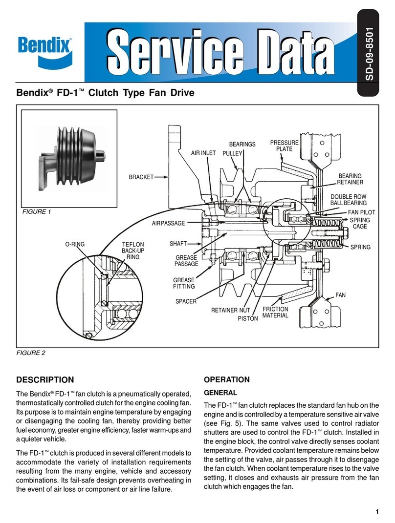
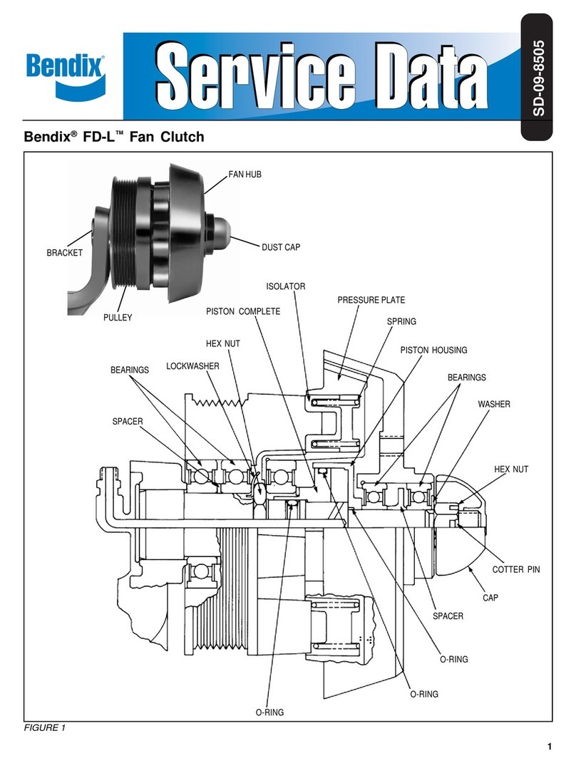
BENDIX FD-3 TORQUEMASTER F-C User manual

1
®
DUST
CAP
LOCK NUT
BEARINGS
PILOT DIAMETER
2.560
Bendix®FD-3™TorqueMaster Fan Clutch
SD-09-8504
PRESSUREPLATE
BEARINGS
FIGURE 1
SHAFT
PISTON
DRIVEPIN(2)
RETURN SPRINGS (8)
AIRINLET
FANHUB
PISTON HOUSING
BEARINGS LOCK
NUT
DUST
CAP
STANDARD PILOT
DIAMETER 1.998
O-RINGS
PULLEY
BRACKET
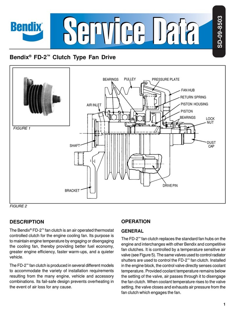
DESCRIPTION
TheBendix®FD-3™TorqueMasterfanclutchisanairoperated
thermostat controlled clutch for the engine cooling fan. Its
purpose is to maintain engine temperature by engaging or
disengaging the cooling fan, thereby providing better fuel
economy,greater engineefficiency,faster warm-upsand a
quietervehicle.
TheFD-3™fanclutchisproducedin severaldifferentmodels
to accommodate the variety of installation requirements
BRACKET
FANPLATE
PULLEY
DUST
CAP

2
FIGURE 3
FANDISENGAGED
FIGURE 2
FANENGAGED
resulting from the many engine, vehicle and accessory
combinations. Its fail-safe design prevents overheating in
the event of air loss for any cause.
OPERATION
GENERAL
The FD-3™TorqueMaster fan clutch replaces the standard
fanhubs onthe engine andinterchanges withother Bendix
and competitive fan clutches. It is controlled by a
temperature sensitive air valve. (See Figure 4). The same
valves used to control radiator shutters are used to control
the FD-3™TorqueMaster. Installed in the engine block, the
controlvalvedirectly sensescoolant temperature.Provided
coolanttemperature remainsbelow thesetting ofthe valve,
air passes through it to disengage the fan clutch. When
coolant temperature rises to the valve setting, the valve
closesand exhausts airpressure from thefan clutch which
engagesthe fan.
Dependinguponoptionalequipment installedonthe vehicle
such as radiator shutters and radiator mounted air
conditioning condenser, different piping arrangements are
necessary. These will be explained in the paragraph on
controlsystems.
DISENGAGED
When the vehicle is started with a cold engine the
thermo-pneumatic control valve is open.As brake system
airpressure isbuiltup, airpasses through thecontrol valve
to the fan clutch. Air enters the inlet port in the bracket of
thefan clutchand travels throughthe drilledpassage in the
shaft to fill the piston cavity. When air in the piston cavity
reaches a pressure of 70-75 psi, the piston slides on the
shaftmovingthepressureplate assemblytothedisengaged
position. In this position the clutch lining is out of contact
with the fan plate and the fan is no longer driven by the
engine(see Fig. 2).
ENGAGED
As the engine coolant rises in temperature, the engine
thermostat opens to circulate radiator coolant through the
engine.When the enginecoolant temperature reachesthe
setting of the control valve, the valve exhausts air from the
piston cavity. The fan clutch springs force the piston and
pressure plate forward on the shaft. When the lining
contacts the fan plate, the fan is engaged and is driven by
the engine (see Figure 3).
CONTROL SYSTEMS
Thefanclutch,in additiontoits primaryfunctionof operating
the fan as needed to maintain the cooling liquid within a
certaintemperature range, must becoordinated with other
deviceswhen installed onthe vehicle.
Theseareradiatorshuttersandradiatormountedcondenser
for air conditioning. Four basic configurations are possible
asfollows:
FIGURE 4. FAN CLUTCH ONLY
FIGURE 5. FAN CLUTCH WITH SHUTTERS
FIGURE 6. FAN CLUTCH WITH RADIATOR MOUNTED
CONDITIONING CONDENSER
FIGURE 7. FAN CLUTCH, SHUTTERS AND CONDENSER
Theobjectivein thecaseof Figure5is tonotengage thefan
until the engine thermostat is fully open. The thermo-
pneumatic control valve should therefore be calibrated to
release the air from the fan clutch when the coolant
temperatureisat least10°F higherthanthe shutteropening
point. If the shutters are the modulating type, the fan
engagement should be at least 10°F higher than the full-
opentemperature of theshutter.
Inthe caseof Figure6the fanmust becontrolled toperform
the supplementary function of pulling cooling air through
theair conditioningcondenser whenrequired, althoughthe
engine coolant may be below the fan cut-in temperature.
This is most likely to occur at high ambient temperatures
PISTON SHOULD
MOVEFORWARDAS
AIRISEXHAUSTED

3
FIGURE 5
FIGURE 7
FIGURE 6
FIGURE 4
THERMO-PNEUMATIC
VALVE
THERMO-PNEUMATIC
VALVES
BLOCK
FAN
CLUTCH
RADIATOR
RADIATOR
FAN
CLUTCH
BLOCK
SHUTTER
BLOCK
BLOCK
THERMO-PNEUMATIC
VALVE
THERMO-PNEUMATIC
VALVE
FAN
OVERRIDE
SWITCH
AIR
CONDITIONING
SIGNAL
AIRCOND. COMPRESSOR
SOLENOIDVALVES
(NORMALLYOPEN)
FAN
CLUTCH
RADIATOR CONDENSER
RECEIVER
DRYER
AIR
CONDITIONER
OVERRIDE
SWITCH
FAN
CLUTCH
RADIATOR
SOLENOIDVALVE
AIR
CONDITIONING
SIGNAL
AIR
CONDITIONING
OVERRIDE
SWITCH
FAN
OVERRIDE
SWITCH RECEIVER
DRYER
CONDENSER
AIRCOND.
COMPRESSOR
Mostvehiclesalsohavean additionaldualfunctionpressure
switch connected in series with the air conditioner clutch.
This switch is normally open, closes at approximately 30
psi and opens again at approximately 400 psi. Its purpose
isto prevent operationof the airconditioning compressor if
the refrigerant is lost or to shut off the compressor if the
system pressure reaches a dangerously high pressure
(approximately400psi). Thisswitchdoesnot normallyhave
anythingto do withfan operation; however, it is sometimes
combinedwith the previouslymentioned override switch.
Figure 7 depicts a combination of shutters, fan clutch and
airconditioning. Thiscombination requires thetwo thermo-
pneumatic controls for fan and shutters, as well as the
electro-pneumatic override for the air conditioning. With
thiscombinationthesamerequirementsforfan controlapply
asin Figure5 and6 withthe additionalrequirement thatthe
shutters should be controlled in such a manner that they
always open whenever the air conditioning compressor
operates.
A variation of this combination consists of a two section
shutter with one section in front of the condenser and the
otherin front of theremaining portion of theradiator.In this
combinationonlythesection infrontofthe condenserneeds
to open when the air conditioner engages.
PREVENTIVEMAINTENANCE
There is no need for periodic maintenance; however, the
following service checks should be made to ensure proper
function of the fan clutch.
GENERAL
The condition of the two fan plate ball bearings should be
checked at regular intervals to ensure proper operation of
the FD-3™fan clutch. The procedure presented here is
intended to check excessive bearing play by measuring
andlowroadspeedoridling.Ifthecondenserisinadequately
cooled, the air conditioning system will start to build up a
higherthan normal pressure. Therefore,a pressure switch
isconnectedinto theair conditioningcompressordischarge
line,asshowninFigure6.Whenthispressureswitch senses
ahigherthan normalpressurein theairconditioning system
(approximately250 psi), itcloses an electricalcircuit which
inturnenergizes asolenoid operatedairsupply valvewhich
exhausts the air supply for the fan control, causing the fan
toengage.
SHUTTER
IGNITION

4
FIGURE 8
FANPLATE
lateralmovement of thefan plate relativeto the edgeof the
pulley or a scribed line in the dust shield.
CHECKING PROCEDURE
1. Park thevehicleona levelsurfaceandblock thewheels.
2. Shut off the engine and apply a minimum of 85 p.s.i. to
thefan clutchtodisengage it.NOTE: If airbrakesystem
pressure is above 85 p.s.i. and the engine is cool, the
FD-3™fanclutch willbe disengaged. Disengagementis
confirmedby notingthat thefan canbe rotatedfreely by
hand. DO NOT PERFORM THIS CHECK WITH THE
ENGINERUNNING.
3. WiththeengineoffandtheFD-3™fanclutchdisengaged,
graspthe tip of onefan blade using onlythe thumb and
indexfinger. (RefertoFigure 8.)Usingamoderate force,
rock the fan blade back and forth toward the radiator
andmeasurethetotal movementofthefan platerelative
to the edge of the pulley.
Replaceor repairthe fan clutchif thetotal movement of
the fan plate is 1/16" or greater.
ALTERNATEMETHOD - usingthumb andindex finger,
pull the fan blade toward the engine with a moderate
force and scribe a line on the dust shield along the
edge of the fan plate. After scribing the lines, push the
fanblade towardthe radiatorand measurethe distance
between the scribed line and the edge of the fan plate.
(Alternatemethod notillustrated.)
Replaceor repairthe fan clutchif thetotal movement of
the fan plate is 1/16" or greater.
LINE HAUL VEHICLES
Every 50,000 miles; 1,800 hours, or every six months,
whicheveroccurs first,performthe servicechecks outlined
inthis manual.
CITY DELIVERY
Every 15,000 miles, 300 hours or two months whichever
occurs first, perform the service checks outlined in this
manual.
SERVICE CHECKS
Before performing the operational and leakage checks,
apply the vehicle parking brakes or chock the wheels.
OPERATIONAL
1. With the engine cold, the ignition off and at least 75 psi
air pressure in the brake system, note that the fan is
disengagedfrom thepulley and canbe turnedbyhand.
Ifthe fan can beturned, proceed to Step#2. If it cannot
be turned;
A. Drain all reservoirs and disconnect the air control
line leading to the fan clutch and apply at least 75
psi shop air pressure to the fan clutch.
B. If the fan cannot be turned, the clutch is defective
and must be repaired or replaced (see appropriate
section of this manual).
C. If the fan can now be turned; check the air lines
leadingtoandfromthethermostaticcontrol valvefor
‘kinks’ or obstructions, and check the control valve
itselfaccording to the manufacturer’sinstructions.
2. Afterperformingcheck #1,drainall airpressurefromthe
brake system. Note that the fan is now engaged and
cannotbeturnedbyhand. Ifitcannotbe turned,proceed
totest #3. If itcan be turned, theclutch is defective and
mustbe repairedor replaced.
3. Checktheoperationofthe thermostaticcontrol valveby
runningthe engineup tooperating temperature.
Note that the fan clutch engages when engine
temperature rises to normal or above and disengages
afterfan cooling isaccomplished. Normal engagement
timeshouldnotexceedtwo minutes.Ifengagementtime
does not exceed two minutes, proceed to check #4. If
engagementtime doesexceed twominutes:
A. If this test is being performed for the first time after
installation of the fan clutch, recheck the setting of
the thermostatic control valve and compare it with
thesetting ofthe enginecoolant thermostatorin the
case of vehicles with radiator shutters, with the
setting of the shutter control. The fan clutch control
shouldalwaysbe10°Fhigherthanthehighestsetting.
DUST SHIELD
PULLEY
THE TOTAL CHANGE IN THIS
DIMENSION FROM ITS
NARROWEST TO WIDEST
MEASUREMENT SHOULD
NOT BE 1/16” OR GREATER

5
B. Ifthe fanclutch installation hassuccessfully passed
this test before, but does not do so now, the
thermostaticcontrolvalve isdefectiveandshould be
replaced.
4. With the clutch in the engaged position (control air
vented),checkthecondition ofthedrive pinsandmating
holes in the pressure plate by attempting to rotate the
fanclockwiseandcounterclockwise.If freeplayexceeds
5/16” (8 MM), fan clutch must be repaired or replaced.
LEAKAGE CHECKS
In order to check for air leakage past the only two sliding
o-ringsinthe FD-3™TorqueMasterfan clutchit isnecessary
to disconnect the single air control line.
Checkforleakagebyconnectinga90cu.in.reservoir(Bendix
part number 225000) with a gauge installed to the control
portof thefan clutch.Afterfilling the90 cu.in. reservoirwith
100 psi, allow the pressure to stabilized and observe the
time required for the reservoir pressure to drop to 90 psi. If
thetimerequired islessthan 1minute,leakage isexcessive
andrepair orreplacement is necessary.
WARNING! PLEASE READ AND FOLLOW
THESE INSTRUCTIONS TO AVOID
PERSONAL INJURYOR DEATH:
When working on or around a vehicle, the following
general precautions should be observed at all times.
1. Park the vehicle on a level surface, apply the
parking brakes, and always block the wheels.
Always wear safety glasses.
2. Stop the engine and remove ignition key when
working under or around the vehicle. When
working in the engine compartment, the engine
should be shut off and the ignition key should be
removed. Where circumstances require that the
enginebe in operation, EXTREMECAUTION should
be used to prevent personal injury resulting from
contact with moving, rotating, leaking, heated or
electrically charged components.
3. Do not attempt to install, remove, disassemble or
assemble a component until you have read and
thoroughly understand the recommended
procedures. Useonly the proper tools and observe
all precautions pertaining to use of those tools.
4. If the work is being performed on the vehicle’s air
brake system, or any auxiliary pressurized air
systems,makecertainto drain the air pressure from
all reservoirs before beginning ANY work on the
vehicle. If the vehicle is equipped with an AD-IS™
air dryer system or a dryer reservoir module, be
sure to drain the purge reservoir.
5. Following the vehicle manufacturer’s
recommendedprocedures, deactivate the electrical
system in a manner that safely removes all
electrical power from the vehicle.
6. Never exceed manufacturer’s recommended
pressures.
7. Never connect or disconnect a hose or line
containing pressure; it may whip. Never remove a
component or plug unless you are certain all
system pressure has been depleted.
8. Use only genuine Bendix®replacement parts,
components and kits. Replacement hardware,
tubing, hose, fittings, etc. must be of equivalent
size, type and strength as original equipment and
be designed specifically for such applications and
systems.
9. Components with stripped threads or damaged
parts should be replaced rather than repaired. Do
not attempt repairs requiring machining or welding
unless specifically stated and approved by the
vehicle and component manufacturer.
10. Prior to returning the vehicle to service, make
certain all components and systems are restored
to their proper operating condition.
REMOVAL
Itis recommended thatthe FD-3™TorqueMaster fanclutch
be removed from the vehicle for service even though it is
possible on some installations to install kits 104937 and
104938without clutchremoval.
1. Secure the vehicle on a level surface by means other
than the brakes.
2. DrainALLreservoirs to 0 psi (0 kPa) air pressure.
3. Disconnect the air line from the fan clutch.
4. Removethesix capscrewsand lockwashersthatattach
thevehicle’sfantothefanplateoftheFD-3™TorqueMaster.
5. Removethefan.NOTE: Removeandretainanyspacers
that may be installed between fan and fan plate
assembly.
6. Loosen,remove andretain the vehicle’sfan belts.
7. Remove the attaching hardware from the fan clutch
mounting bracket and remove the fan clutch from the
vehicle.
DISASSEMBLY (Refer to Figure 9)
1. Removethe dustcap(1) bypulling itoff ofthe endof the
shaft.
2. Removethe cotter pin(2)from the lock nut(10).
3. Removethe locknut(10).
4. Removethe fan plate assemblyand set aside.
5. Slidethe pistonhousing(15)and piston(16)offthe shaft.
6. Separatethepiston(16)from thepistonhousing(15)and
removethe o-rings(4 &5) from thepiston.
7. Removeo-ring(3)fromtheshaft.
8. Remove pressure plate(7) from the shaft. Remove the
four o-rings(6) from the drive pin holes in the pressure
plate.
9. Removethetwo1/4”x20Phillipsheadscrewsthatsecure
thespringpack(9)to thepulley.Removethespring pack.
10. Removetheanti-rotation spring(17).
11. Using a drift punch, disengage the locktab of the
lockwasher(23)from the notchof thelocknut(18).

6
FIGURE 9
12.Using a Spanner wrench, remove the locknut(18) and
the lockwasher(23). NOTE: See Figure 10 for
instructionsto fabricate a Spannerwrench.
13. Supportthepulleysothattheshaftandbracketassembly
can be pressed out of the pulley assembly. Since the
bearings(19)areoriginallyinstalled withLoctitebetween
the shaft and the bearing race, a force as high as 5000
lbs.may be requiredto separate theseparts.Press the
shaftand bracketassembly out of thepulley assembly.
PULLEY DISASSEMBLY (see Figure 11)
1. Support thepulley sothat thetapered retainingring(22)
is visible. Displace the bearing spacer(20) so that it is
eccentric to the bearing bore as far as possible. Insert
around pressingtool throughthe I.D.ofthe bearing(19)
until it contacts the spacer. Press out the lower
bearing(19) and bearing spacer(20). Discard the
bearing.
2. Remove thetapered retaining ring(22).
3. Turnthepulleyoverandpresstheremainingbearing(19)
out of the pulley. Discard the bearing.
4. Remove the retaining ring(21) from the pulley.
FAN PLATE DISASSEMBLY WITH PILOT
DIAMETER OF 1.998
1. Support the fan mounting surface of the fan plate
assemblymakingcertain sufficientspace isleftbeneath
to permit the ball bearings(11) to be pressed out.
Key
No. Qty. Description
1 1 Cap
2 1 CotterPin
3 1 O-ring
4 1 O-ring
5 1 O-ring
6 1 O-ring
7 1 PressurePlate Complete
8 2 1/4" Sems Screw
9 1 SpringPack
Key
No. Qty. Description
10 1 FlangeNut
11 1 BallBearing
12 1 Spacer
13 1 BallBearing
14 1 RetainingRing
15 1 PistonHousing
16 1 PistonComplete
17 1 Anti-rotationSpring
18 1 Locknut
19 2 BallBearing
20 1 Spacer
21 1 RetainingRing
22 1 RetainingRing
23 1 Lockwasher
Key
No. Qty. Description
10 1 FlangeNut
11 1 Ball Bearing
12 1 Spacer
13 2 BallBearing
14 1 RetainingRing
15 1 PistonHousing
16 1 PistonComplete
17 1 Anti-rotationSpring
18 1 Locknut
19 2 BallBearing
20 1 Spacer
21 1 RetainingRing
22 1 RetainingRing
23 1 Lockwasher
PILOT DIAMETER 1.998 PILOT DIAMETER 2.560
3
3
PILOT DIAMETER
2.560
PILOT DIAMETER
1.998
20
9
8
4
4
7
22
19
621 18 17
23
510 1
2
515 14 13 11
16
10
1
12
716 15 14 12 11
13
2

7
FIGURE 10
MATERIAL O.H.T.S. TUBING
HDN.&DRAW.RC40-45
27/32” DRILL THRU
(2 HOLES FOR 3/4”
BAR”
2-3/4”
.235 + - .002 CENTERED
(4 LUGS)
FIGURE 11
DRIVEPINS
PULLEY
22
19
SEAL
19
20
21
SEAL
Displace the bearing spacer(12) so that it is eccentric
to the bearing bore as far as possible. Insert a round
pressing tool through the I.D. of the ball bearing(13)
until it contacts the spacer(12). Press the ball
bearing(11) and the bearing spacer(12) out of the fan
plate. Discard the bearing because it will be damaged
bydisassembly.
2. Remove retaining ring(14) using Waldes tool #6500.
Turnfanplateoverandpress outremainingbearing(13).
Discard the bearing.
FAN PLATE DISASSEMBLY WITH PILOT
DIAMETER OF 2.560
1. Remove theretaining ring(14) fromthe fanplate.Place
the fan plate on a firm surface and utilizing a round
pressing tool, press out the two ball bearings(13) and
the spacer(12). Discard the bearings.
REASSEMBLY
ASSEMBLY OF PULLEY (Refer to Figure 11)
1. Install snap ring(21) using Waldes tool #6500 or
equivalent.
2. Support the pulley on the drive pin end and press one
of the bearings(19) (seal side up) into the pulley until it
contacts the snap ring(21). Use a pressing tool that
contacts the outer race of the bearing.
3. Turn the pulley over and position the spacer(20)
concentricwith theinner raceof thepreviously installed
bearing.Pack grease (ExxonUnirex N-2 orequivalent)
around the spacer making certain not to overfill the
volume. Support both the inner and outer race of the
previously installed bearing. Press in second
bearing(19) (seal side up) using a tool that contacts
both the inner and outer race until the inner race of the
bearing contacts the spacer(20).
4. Turnthe pulleyoverandinstallthetaperedsnapring(22)
(flat side towards the bearing) making sure the snap
ring is fully seated in its groove.
ASSEMBLY OF PULLEY ONTO THE BRACKET
AND SHAFT
1. Support the bracket with the shaft pointing up. Apply
one bank of Loctite RC609 around the shaft at the
locationof inner races ofthe bearings(19) in thepulley.
Also put a band of the Loctite on the inner races of the
bearings(19). NOTE: Parts must BE free of oil and
grease for Loctite to properly bond.
2. Slide the pulley onto the shaft, making sure the bottom
bearings inner race(19) contacts the bracket. Allow 24
hours for complete curing of the Loctite to take affect.
3. Place lockingring(23)ontheshaft andinstalllocknut(18)
usingthesame toolas Step 12of ‘Disassembly’.Torque
locknut to 100-150 ft. lbs. until one of the tangs of the
lockring(23) can be bent up into one of the slots of the
locknut. Never back the torque off to align parts.
ASSEMBLY OF FAN PLATE WITH 1.998 PILOT
DIAMETER
1. Support thefanplate onthe fanmounting surface(nose
down) and press bearing (13) into the housing until it
bottoms against the shoulder of the fan plate. NOTE:
Use a pressing tool that contacts the outer race of the
bearing, do not use a load greater than 1100 lbs. to
press bearing into bore.
2. Turn fan plate over and fully support the previously
installed bearing (13) both inner and outer race. Install
spacer (12) concentric with the inner race of bearing
(13). Press in bearing (11) with a tool that contacts
boththeinner andouterrace andwith aforceno greater
than 1100 lbs. until the inner race contacts the spacer.
2.125+ .010
1/32” FLAT

8
FIGURE 12
The spacer (12) should be tight against both bearing
inner races, yet be able to be moved by a finger load.
3. Turnthefan plateover andinstallsnap ring(14)with the
flat side towards the bearing, making certain the snap
ring is fully seated in its groove.
ASSEMBLY OF FAN PLATE WITH 2.560 PILOT
DIAMETER
1. Supportthefanplateon thefan mountingsurface (nose
down). Using a pressing tool that contacts the outer
bearing race only, press ball bearing (13) into the fan
plate using a force no greater than 1100 lbs. Until it
contacts the fan plate shoulder. Install the bearing
spacer(12) (as illustrated in Figure 1) concentric with
the inner race of the ball bearing previously installed.
2. Continue tosupportthefan plate(nosedown) andpress
bearing(11)using apressingtool thatcontactstheouter
race of the bearing only. Carefully press the bearing
with a force no greater than 1100 lbs. until the inner
bearing race contacts spacer (12). Do not continue
pressing the bearing once the inner race has touched
thespacer; severe damage tothe bearings may result.
As a check after assembly, the bearing spacer should
betight againsteach bearingrace yetableto bemoved
by a finger load.
3. Turn the fan plate over and install snap ring (14) with
the flat side towards the bearing, making certain the
snap ring is fully seated in its groove.
FINALASSEMBLY
1. Support the bracket, shaft, and pulley assembly with
the shaft pointing up.
2. Install spring pack (9) onto the pulley assembly and
retain with the two 1/4"x20 Phillips screws. Torque to
50-75 inch pounds.
3. Install the anti-rotational spring(17) making sure one
end of the spring is engaged in the notch of the shaft.
(See Figure 12)
4. Apply a thin film of silicone lubricant BW-655M to the
four o-rings(6). Position the o-rings into the grooves
located in the drive pin holes of the pressure plate(7).
Applythe same lubricantto the drivepins on thepulley.
5. Install the pressure plate(7) onto the pulley assembly
making sure the end of the antirotational spring(17) is
engaged in the notch of the spring collar on the I.D. of
the pressure plate. Holes in the pressure plate must
slide over the drive pins.
6. Lubricate the I.D. of the piston housing(15) and the
three o-rings (3,4, & 5) with lubricant used in Step 4.
Install o-rings (4&5) onto the piston and o-ring (3) onto
theshaft.
7. Installpiston(16) into thepiston housing(15) and install
unit onto the shaft.
8. Installfan plate assemblyonto the shaftandretain with
the locknut(10). NOTE: On unit with 2.560 diameter
hub,washer(11)tobeinstalledbeforethelocknut.Torque
to 90 to 100 ft.lbs.
9. Install cotter pin(2) and bend to hold in place. Replace
cap(1).
INSTALLATION
1. Attach fan clutch unit to vehicle by installing cap nuts
and lockwashers through mounting bracket holes into
mating holes in engine bracket.
2. Reconnect air line to unit.
3. Adjust fan belts per vehicle manufacturer’s
recommendation.
4. Replace fan on pressure plate with six cap screws and
lockwashers.Torque to 300-360inch pounds. (Besure
to install any spacers that were removed during
disassembly.)
5. Performservice checksas previously outlined.
TEST
1. Withnoairpressureapplied,thetorquerequiredtorotate
the clutch must not exceed 150 in. oz.
2. With70-75psi applied,thefan platemust separatefrom
thepulley and rotatefreely.
3. Perform the leakage checks outlined in the manual.
RETROFIT INSTALLATION
INFORMATION
To determine which fan clutch piece number should be
purchasedwhen retrofittingexisting equipment,consult the
nearestauthorized Bendix distributorfor assistance.
Completeinstallation instructions and piping diagrams are
packedwith eachFD-3™TorqueMaster fan clutch.
It is recommended that only cooling fans approved by the
vehicle or fan manufacturer be installed on the
FD-3™TorqueMaster.
Maximum weight of fan blade assembly is 30 lbs.
Maximum R.P.M. of 28 inch fan is 2700.
Maximum R.P.M. of 34 inch fan is 2100.
Maximumthicknessof spacers between fan and hub plate
is 1-1/2".
ANTI-ROTATIONAL
SPRING ONE END OF SPRING
INSTALLED IN NOTCH
INSPRINGCOLLAR
ONE END OF SPRING INSTALLED
IN NOTCH OF THE SHAFT
BW1452 © 2004 Bendix Commercial Vehicle Systems LLC All rights reserved. 4/2004 Printed in U.S.A.
Table of contents
Other BENDIX Fan manuals
Popular Fan manuals by other brands

Casablanca
Casablanca M6011-01 user manual

Cool Air
Cool Air NBCXM54L Installation, operation and maintenance instructions

Giacomini
Giacomini KFC-F Installation and user manual

Sonnenkonig
Sonnenkonig CATANIA user manual

Fantech
Fantech Ezifit installation instructions

Ansult
Ansult 022491 operating instructions