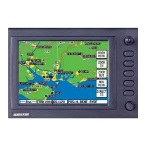
BENDIXKing Skymap IIIC Manual

Pilot’s
Guide
KFC
400
Flight Control System

This Pilot’s Guideprovides a general description
of
the vario
rational characteristics
of
the
KFC
400
Flight Control System.
ver, operation
of
the system should not be attempted without

Introduction
The KFC
400
Flight ControlSys-
tem combinescomplete autopilot and
flightdirector computationfunctions in
asingle computer.
Its
digitalflight
computer and integratedarchitecture
enable the KFC
400
to determine air-
craftcontrolrequirementssooner, and
to executethem with greater smooth-
ness and accuracy than previous au-
topilotsystems.
Due primarily to itsdualchannel
flight computer design, the KFC
400
can more positively control the air-
craft while providing a level
of
safety
monitoring unavailablewith single
channel systems. Digital, solid-state
design throughout the Flight Control
System provides maximumreliability
while economizingonsystem weight
and required installation space.
The KFC
400
is designedto opti-
mize passenger andflightcrewcom-
fort, white stillprovidingaccuratecon-
trol responsein any flight situation.
Wherever possible, autopilot-induced
aircraft motionsborder on the lower
limitsof human perceptibility, ensuring
exceptionally smooth flight. Many of
the Flight Control System's maximum
commandablevalues, however, are
determinedfor each individual aircraft
during the Flight ControlSystem
certificationprocess. Consult the
KFC
400
Flight ManualSupplement
foryour aircraft for particular values.
and vertical flightdirector modesthe
KFC
400
provides automatic, three-
dimensionalflight controlwhen inter-
facedwith the
KNS
660
Flight Man-
agement System. With eachway-
point in aflight plan assigned an alti-
tude, the KFC
400
can command
climbs
or
descents for perfect altitude
operation.
Inaddition to afull rangeof lateral
1
Internalsafety monitorsand auto-
matic self-test functions keepconstant
track of the KFC
400's
status, and
providesignals for automatic shut-
down of impairedcontrolaxes or flight
director functions. When the
KFC
400
decouples an autopilot axis it both
disengagesthe affected servo clutch
and shuts off motor drivepower, pro-
viding dual layers of protection
against servo overcontrol.
Inaddition to reliability and light
weight, the KFC
400
isdesigned to be
easy to maintain inthe field. Self-con-
taineddiagnostic tests assisttrouble-
shooting done by maintenanceper-
sonnelat BendixMing factory-ap-
proved service centers. The test func-
tions enable a technician to trace a
fault
to
the individual circuit board, or
externalsensor concerned. Circuit
boards inside remote-mounted
components areinstalledvertically, to
prevent condensation pooling.
Circuitry with the highest heat dissi-
pationrequirements are located near-
est the walls of each component
enclosureto optimize thermalman-
agement and serviceability. Qualified
Bendix/King service centersaround
the world are ready to provide assis-
tance whenever necessary.
The KFC
400
can interfacewith
electromechanical flight instruments
or the latest electronic displays, as
wellas navigation systems, radar al-
timetersand other peripheralcompo-
nents. All of the KFC
400's
digital
interfaces are based on ARlNC
429
specifications, and analog/digital con-
verters are supplied wherever neces-
sary to providethe greatest interface
versatility.

Table
of
Contents
introduction
.........................................................................................
1
System
Components
.........................................................................
4
Operational
Specifications
..............................................................
6
Operational
Capabilities
..................................................................
8
Component
Descriptions
Cockplt
Components
KMS
446
Flight DirectorMode Selector
.................................
10
KMC
440
Autopilot ModeController
.......................................
14
KHC
441
Heading and CourseController
..............................
16
KHC
442
Heading and CourseController
..............................
17
ControlWheel Switch Assembly
............................................
18
Go-Around Pushbutton
...........................................................
19
KAP
419
Annunciator Panel
...................................................
19
Electromechanical Display Units
............................................
20
EFS
10
Display Units
.............................................................
25
KAV
485
AltitudeNerticalSpeed Indicator
.............................
26
KST
488
SpeedflemperatureIndicator
..................................
29
Remote-Mounted
Units
KCP
420
FlightComputer
......................................................
30
KDA
430
GyroAdapter
...........................................................
30
KAM
432
Autopilot Monitor
.....................................................
30
KSA
470
Servo Actuator
........................................................
31
KDC
481
CentralAir Data Computer
.....................................
31
Preflight
TesVStartup
Procedures
...............................................
32

Flight Director Operations
RollAttitude HoldpitchAttitude Hold
............................................
35
Control
Wheel
Steering
.................................................................
35
Heading
.........................................................................................
35
Nav
...............................................................................................
35
Approach
.......................................................................................
36
Flight Director
................................................................................
36
Mach
..............................................................................................
36
VNAV
.............................................................................................
37
Altitude Hold
..................................................................................
37
Altitude Select
................................................................................
38
Climb
.............................................................................................
38
Descent
.........................................................................................
38
IndicatedAirspeed Hold
................................................................
39
Vertical Speed
...............................................................................
39
Go-Around
.....................................................................................
39
Autopilot Operations
Autopilot
.........................................................................................
40
Yaw Damper
..................................................................................
41
Half Bank
.......................................................................................
41
Soft
Ride
........................................................................................
41
RollAttitude Control
.......................................................................
41
Vertical Trim
..................................................................................
42
Operational Examples
Takeoff and Climb
.........................................................................
44
VNAV Descent
...............................................................................
46
Outboundon Front Course
............................................................
48
Front Course ILS
...........................................................................
50
Abnormal Procedures
.....................................................................
52
Emergency Procedures
..................................................................
54
3

The KFC400 Flight ControlSys-
tem is designed
to
locateall mode
andfunctioncontrolswithin conven-
ient reach
of
the pilot and to provide
clear, easily interpretedinformation
displays. Thefollowing components
are included inthe FlightControl
System.
Cockpit
Units
1
KMS446 Flight Director Mode
KMC440 Autopilot ModeController
m
488
Selector
KHC441 or KHC
442
Course/
HeadingController (electro-
mechanicalor electronicflight
instrument installations)
ControlWheel SwitchAssembly
Power LeverGo-AroundPushbutton
KAP41
9
Annunciator Panel
(electromechanicalflight instrument
installationsonly)
ElectromechanicalDisplay Units
EFS
10
Display Units
KAV 485 AltitudeNerticalSpeed
KST488 Speedmemperature
Indicator
Indicator (optional)
Remote-Mounted Units
KCP 420 FlightComputer
KDA 430 Gyro Adapter
KAM432 Autopilot Monitor
KSA 470 Servo Actuators
KDC481 CentralAir DataComputer
KAY
485
T
I
4

Dual
KFC
400
System
Diagram
I
ED
102
ED
loZ
I
1
KAV
485
5

Operational Specifications
ControllersC52a, C9c Panel
Units
Remote Units C52a, C9c
Servos
C9c
KAP 419 KAV 485 KCP420 KSA 470
KMS446 (C~C,ClOb) KDA 430
(plus
C87,
KMC440 C41c, C~C,
C4c)
KHC
441
KST488 (C43a) KAM432
KHC442 KDC481 (C~C,C8c,
ClOb, C43a,
C46a,
C88a, C95)
Environmental
Cate
Controllers Pane
Altitude
55,000
ft.
55,000
ft.
Temperature
-20' to +70°C -20' to +70°C
Temperature Variation
6
C
Humidity
A
Vibration
KPS KPS
Explosion Proof
X
X
A
55,000
ft.
55,000
ft.
-55'
to +7OoC
65'
to +7OoC
B
A
MNO
El
B
A
JLY
El
6

Unit Weight Dimensions
(H
x
W
x
L)
(Ibs)
KGs)
(IN)
(CM)
KAP 419
KCP 420
KDA
430
KAM 432
KMC 440
KHC
441
KHC 442
KMS
446
KSA 470
KSM 475
KDC
481
KAV
405
KST
488
KCI
310
KRG 332
.3
8.0
2.6
2.4
1.3
1.7
.6
1.2
3.0
1.4
3.7
3.6
.a
5.0
4.2
6.0
6.8
.a
4.8
.3
.2
.14
3.63
1.2
1.07
.6
.77
.27
.54
1.36
.63
1.68
1.63
.37
2.27
1.93
2.72
3.1
.34
2.18
.14
.1
1.1
x
4.3
x
4.5
5.3 x
5.5
x
13.7
5.3
x
2.0
x
12.8
5.3
x
2.0
x
12.8
1.9 x
5.8
x
7.3
1.9
x
5.8
x
7.3
1.5
x
5.8
x
3.9
1.9
x
5.8
x
7.3
3.5
x
4.2
x
3.7
3.9
x
4.2 x 2.2
5.3
x
3.1 x 13.6
6.2 x 3.4
x
9.1
1.7
x
3.4
x
7.3
4.3
x
4.3
x
9.4
4.3
x
4.3
x
10.4
4.3
x
4.3 x 9.1
5.4
x
5.5
x
9.92
2.1
x
2.2
x
5.0
5.4
x
7.8
x
4.3
3.4
dia
x
1.a1
1.2
x
2.1
x
3.0
2.8
x
10.8
x
i
1.4
13.5
x
14.0
x
34.8
13.5
x
5.1
x
32.5
13.5 x 5.1 x 32.5
4.8~14.7~18.5
4.8
x
14.7
x
18.5
3.8
x
13.6
x
9.9
4.8
x
14.7
x
18.5
7.7
x
10.7
x
9.4
9.9
x
10.7 x 5.6
13.5
x
7.9
x
34.5
15.7
x
8.6
x
23.1
4.3
x
8.6
x
18.5
10.8
x
10.8
x
21.2
10.8
x
10.8
x
26.3
10.8
x
10.8
x
23.2
13.7
x
14.0
x
20.1
5.4
x
5.6
x
12.7
13.6
x
19.8
x
10.9
8.5
dia
x 4.6
3.0
x
5.4
x
7.6
7

Operational Capabilities
Mode Parameter
KFC
400
Value
Attitude Hold
Heading Hold
NAV
(VOR Capt)
(VOR Track)
(Over Station)
PitchCommand Limit
PitchCommandAccel Limit
PitchHoldAccuracy
RollAngle Limit
RollCommand RateLimit
Roll
Command Accel Limit
RollHold Accuracy
RollAngle Limit
RollCommand RateLimit
RollCommandAccel Limit
Accuracy
Beam Intercept Angle
Capture Point
RollAngle Limit
RollCommand RateLimit
Roll
CommandAccel Limit
RollAngle Limit
Crosswind Correction
CourseChange
RollAngle Limit
+25 Deg, -15 Deg
.05g
f
.3
Deg SmoothAir
25 Deg
3
DegISec
1.6
DegiSecondISecond
f
1Deg SmoothAir
25 Deg
3
DegISecond
1.6
DegISecondiSecond
f
1 Deg Smooth Air
AllAngle
Function
of
DME, Deviation, Dev
Rate
&
Course Error
25 Deg
3
DegiSecond
1.6 DegiSecondiSecond
25 Deg
UpTo
30
Deg
UpTo
90
Deg
25 Deg
Approach
Beam Intercept Angle Upto 105 Deg Front Course
(LOC Capture) RollAngle Limit 25 Deg
(LOCTrack)
GS
Roll
Command RateLimit
Roll
Command Accel Limit
Capture Point
RollAngle Limit
Cross Wind Correction
Gain Programming
PitchCommand Limit
Capture Point
GS Damping
PitchRate Limit
Gain Programming
6 DegISecond
4
DegISecondiSecond
Function
of
Deviation, Dev Rate
&
Course Error
10 Deg
UpTo
30
Deg
Function
of
RadAlt or
(time, TAS)
+25 Deg, -15 Deg
Function
of
Deviation, Dev Rate
PitchAtt
&
TAS
Max 2 DegiSecondor .15G
Function
of
Rad Alt or
(time, TAS)
8

Mode Parameter
KFC
400
Value
Go-Around
PitchUpCommand
Engage Range
PitchLimit
Engage Vert
Spd
Limit
Max "g"DuringCapture
Engage Range
Engage Vert
Spd
Limit
Accuracy
PitchCommand Limit
PitchRate Limit
IAS
Hold
Engage Range
Accuracy
PitchCommand Limit
PitchRate Limit
Engage Range
Accuracy
Select Range
PitchCommand Limit
PitchRate Limit
Engage Range
PitchCommand Limit
Accuracy
Profile
Engage Range
PitchCommandLimit
Accuracy
Vert
Spd
Command
Engage Range
O)
PitchCommand Limit
(When
Installed
Station Elevation
Bias Range
Accuracy
Altitude Range
PitchRate Limit
Engage Range
PitchCommandLimit
Below
9,000
Ft. MSL
9
Selectable
0
to
55,000
Ft.
+
25 Deg,
-15
Deg
f
6,000
FVMin
f
.07g
-1,000
to
55,000
Ft.
f
2,000
FVMin
f
20
Ft, Smooth Air*
+25
Deg, -15 Deg
.l
g Vert Accel
60 Ktsto V,
f
2
Kts, Smooth Air
+
25
Deg,
-15
Deg
.15g Vert Accel
f
6,000
FVMin
f
50
Ft/Min*
f
6,000 FVMin
+
25
Deg,
-15
Deg
.lG
Vert Accel
60 Ktsto
V,
+
25
Deg,
-15
Deg
f
2 Kts
Selectable
f
6,000 Ft.
+25
Deg,
-15
Deg
f
50
FVMin*
Selectable
f
6 DegVTA Max (Certification)
Stored in660 Memory
+25
Deg,
-15
Deg
f
99.9
Mi
f20
Ft
0
to
55,000
Ft.
.lG
Vert Accel
UP
to Mmo
f
.005
MACH, Smooth Air
f
25
Deg,
-15
Deg

Component Descriptions
KMS
446
Flight
Director Mode Selector
16
17
18
19 20 21
I
I I
I I
I
I
22
I
23
I
24
I
25
I
26
I
27
10
11
12
13
14 15
16
17
18
19 20 21
I
112345161
7189)
unuuuu
'1
10
11
12
13
14 15
10

The
KMS
446
modeselector pro-
vides
control
and annunciationof the
KFC
400's
Flight Director modes. Illu-
minationof the annunciations is ad-
justed automatically by a photocell
locatedontheface of the unit.
Display
Features
Mode
Annunciations
1.
HDG
(headingselect)
-
Illumin-
ates when headingselect mode is
engaged bythe headingpushbutton.
Flashing indicates
loss
of a sensor
requiredto hold selected
HDG
(e.9.
invalidmagnetic heading, invalid
se-
lected heading) and continues untila
second pushof the
HDG
pushbutton
to acknowledgeautomatic disengage-
ment of the mode.
2.
NAV
(capture and track selected
navigation sensor)
-
Illuminates
when
NAV
capture or
NAV
track
mode is engaged by the
NAV
push-
button and normally sequenced
through
NAV ARM.
Flashing indi-
cates lossof a sensor requiredto cap-
tureor track the selected nav (e.g.
invalid
NAV,
invalidselected course)
and continues untila second push of
the
NAV
pushbutton acknowledges
automatic disengagementof the
mode.
3.
NAV ARM
(preengagecondition of
NAV)
-
Illuminateswhen
NAV
mode
iscalledfor by the
NAV
pushbutton.
It
allows acompatible lateralmodeto
beusedto interceptthe desired
course or track. Inthe event of a sus-
tained
NAV
invalid,
NAV ARM
willdis-
engage leavingthe current engaged
mode active and allowing later rearm-
ing
of
the
NAV
mode.
4.
APR
(capture andtrack selected
navigationsensor with approach
accuracy)
-
Illuminateswhen ap-
proach capture or approachtrack
mode is engaged by the
APR
push-
button and normally sequenced
through
APR ARM.
Flashing indi-
cates loss of a sensor requiredto cap-
ture or track the selected nav (e.g.
invalid
NAV,
invalidselected course)
and continues untila second push of
the
APR
pushbuttonacknowledges
automaticdisengagementof the
mode.
5.
APR ARM
(preengagecondition
of
APR)
-
Illuminateswhen
APR
mode iscalledfor by the
APR
push-
button.
It
allows acompatible lateral
mode to be used to intercept the de-
sired course. Inthe event of asus-
tained
NAV
invalid,
APR ARM
will
dis-
engage leavingthe current engaged
mode active and allowing rearmingof
the
APR
mode later.
6.
FD (flight director
)
-
Illuminates
when FD or
AP
buttonis pushedor
any flightdirector mode is engaged.
7.
MACH
(Holdcurrent
MACH
refer-
ence speed)
-
Illuminates when the
MACH
hold mode is engaged by the
MACH
pushbutton. Flashing indi-
cates
loss
of a sensor requiredto hold
current reference
MACH
airspeed
(e.g. invalidindicated airspeed) and
continues untilasecond pushof the
MACH
pushbutton acknowledges
automatic disengagement of the
mode.
8.
VNAV
(fly selected vertical track
angle)
-
Illuminates when vertical
navigation mode is engaged by the
VNAV
pushbutton. Flashing indicates
11

loss
of asensor requiredto fly the ver-
ticaltrack angleor achange inthe
VNAV
parameters requiring disen-
gagement (e.g. invalid
VNAV
devia-
tion) and continues untilthe
VNAV
pushbuttonis pushedto acknowledge
automatic disengagement.
9.
VNAV ARM
(preengage condition
of
VNAV)
-
Illuminates when vertical
navigationmode is calledfor by the
VNAV
pushbutton but the aircraft has
not yet reachedthe selected vertical
track angle
(VTA).
It
allows a
compatible vertical mode to be used
to interceptthe desired
VTA.
Inthe
event of invalid altitude or
VNAV
in-
puts,
VNAV ARM
will
disengage, leav-
ingthe current engaged mode active
and allowing rearming
of
the
VNAV
mode later.
10.
ALT
(hold current reference alti-
tude)
-
Illuminateswhen the
ALT
mode is engaged by the
ALT
push-
button
or
by automaticsequencing
through altitude arm and altitude cap-
ture. Flashing indicates
loss
of asen-
sor requiredto holdcurrent reference
altitude (e.g. invalid altitude) andcon-
tinues untila pushof the
ALT
push-
button acknowledges automaticdisen-
gagement of the mode.
11.
(ALT)ARM
(automaticcaptureof
selected altitude)
-
Illuminateswhen
the
ALT SEL
mode isengaged by the
ALT SEL
pushbuttonor Climb,
Descent or
VNAV
modes. Itallows a
compatible vertical mode to be used
to approach the selected altitude. In
the event of sustained invalidaltitude,
ALT ARM
modewill disengage leaving
the current engaged mode active and
allowing rearmingof the
ALT ARM
mode later.
12.
CLB
(climbat specified profile)
-
Illuminateswhen climb mode isen-
gaged by the
CLIMB
pushbutton.
Flashing indicates
loss
of asensor
requiredto fly the stored profile(e.g.
invalidaltitude, invalidindicated air-
speed) and continues until
a
second
push
of
the Climb pushbutton ac-
knowledges automatic disengage-
mentof the mode.
13.
DES(descend at specified verti-
cal
speed)
-
Illuminateswhen
descent mode isengaged
by
the
DESCpushbutton. Flashingindicates
loss
of
a sensor requiredfor descent
mode(e.g. invalidvertical speed) and
continues untila second push of the
DESC
pushbutton acknowledges
automatic disengagementof the
mode.
14.
IAS
(holdcurrent referenceair-
speed)
-
Illuminateswhen the air-
speed hold mode is engaged by the
IAS
pushbutton. Flashing indicates
loss
of
a sensor requiredto hold cur-
rent reference airspeed (e.g. invalid
indicated airspeed) and continues un-
til
a
second pushof the
IAS
pushbut-
ton acknowledges automatic disen-
gagement of the mode.
15.
VS
(holdcurrentor selectedverti-
calspeed)
-
Illuminateswhen the
verticalspeed hold mode is engaged
bythe
VS
pushbutton or by transition
from
DES
mode. Flashing indicates
loss of a sensor requiredto hold se-
lectedverticalspeed (e.g. invalidverti-
cal
speed) and continues untilthe
VS
pushbutton is pushedto acknowledge
automaticdisengagementof the
mode.
12

Control Features
ModeSelect Pushbuttons
16.
HDG (headingselect)
-
Alter-
natelyengages and disengageshead-
ingselect mode.
17.
NAV(capture andtrack selected
navigationsensor)
-
Alternately en-
gages and disengagesthe navigation
mode.
18.
APR (captureandtrack selected
navigationsensor with approach ac-
curacy)
-
Alternately engagesand
disengagesthe approach mode.
19.
FD(flight director)
-
Engages
FlightDirector inpitch attitude hold
andwings levelmode. PressingFD
whenflight director is engagedwill
disengage allflight director modes
if
autopilot is not engaged.
20.
MACH (holdcurrent MACH refer-
ence airspeed)
-
Alternately en-
gages and disengages MACH hold
mode.
21.
VNAV (fly selected vertical track
angle)
-
Alternately engagesand
disengagesVNAV mode.
22.
ALT (holdcurrent referencealti-
tude)
-
Alternately engagesand dis-
engagesaltitude holdmode.
23.
ALT SEL (automaticcaptureof
selectedaltitude) -Alternately en-
gages anddisengagesaltitude arm
mode.
24.
CLIMB
(
climbat specified profile)
-
Alternately engagesand disen-
gages climbmode.
25.
DESC(descendat specified ver-
ticalspeed)-Alternately engages
and disengagesdescent mode.
26.
IAS (holdcurrent referenceair-
speed)
-
Alternately engages and
disengagesairspeed hold mode.
27.
VS (holdcurrent or selectedverti-
calspeed)-Alternately engages
anddisengagesvertical speed mode.
1’

KMC 448
Autopilot Controller
7
8
4
7
5
a
9
I
lo
4
13
I
5
14

The KMC
440
allows engagement
of autopilot modesas well as vertical
trim and rollratecommands. Axis fail-
ure lights are locatedonthe face to
annunciateindividualaxis failures.
Inadualsystem a second column
of
failurelights are provided as well as
an autopilot transfer button and
annunciation.
Display Features
8.
HALFBANK (half bank angle)
-
Alternately engages and disengages
half bank mode.
9.
AP XFER (dualsystems only)
(autopilot transfer)
-
Alternately
selects autopilot control from left
or
rightsides.
10.
YD (yaw damper)
-
Alternately
engages and disengages yaw
damper.
Mode
Annunciations
1.
AP (autopilot)
-
Illuminateswhen
the autopilot is engaged by the AP
pushbutton.
2.
HB (half bank angle)
-
Illuminates
when half bank mode is engaged by
the Half Bank pushbutton.
3.
>
(Dual Systemsonly)
(autopilotcouple IefUright)
-
Illumi-
natespointing left or right alternately
when AP XFER ispushed.
4. YD (yaw damper)
-
Illuminates
when yaw damp isengaged.
5.
SR
(soft
ride)
-
Illuminateswhen
soft ride mode is engaged bythe
SOFT
RIDEpushbutton.
6.
Axis failure lightsilluminate when
the internal monitordetectsafailure in
one of the controlaxes.
Control Features
Mode
Select pushbutton
11.
SOFT
RIDE
(soft
ride) -Alter-
nately engages and disengagessoft
ride mode.
Other Controls
12. Rollrate command knobwhen
turnedfrom its center detent position
cancels existing lateral mode and
engages rollattitude hold. The farther
from center the knobis held, the
faster the autopilot increasesthe
aircraft's bank angle. When released,
the rollattitude stabilizes and the
autopilot holds rollattitude.
13. Vertical Trim allows modification
of certainvertical modes (e.g. altitude,
pitchattitude, MACH, IAS, VS). It
will
cancelvertical modeswhich utilizea
verticaltrack or stored vertical profile
(e.g. Glideslope, VNAV, Climb,
GoAround) and revertto pitchattitude
hold.
Action is either by discrete pushes
to modify a reference by a set amount
or continuous by holdingthe controlin
one position and slewing the refer-
ence.
7.
AP (autopilot)
-
Alternately
engages and disengagesthe autopi-
lot. Also engages Yaw Damper when
the autopilot is engaged.
15

KHC
441
Heading and Course Controller
(Mechanical Instruments Only)
2
\
4
\
/
1
3
Control Features
3.
Heading knob when rotated
1.
Course knobwhen rotated
repositionsthe course arrow on the
KPI
5538.
2.
Center pushbutton(pushdirect)
when pushedrotates course arrow
on
KPI
5538
to obtain acentered
deviation bar.
repositionsthe heading bugonthe
KPI
5538.
4.
Center pushbutton (push sync)
when pushed repositions the heading
bug on the KPI
5538
to under the
lubber line.
16

KHC
442
Heading and Course Controller
(EFS
10
Installations Only)
w
PULL
DIRECT
-
PULL
ON
0
I
PULL
SYNC
I
2
Control Features
1.
Course knobwhen rotatedreposi-
tions the course arrow on the EHSI.
2.
“Pull Direct”
-
When the course
knobis pulledrotatesthe course
arrow onthe EHSIto obtain a
centered deviation bar.
3.
Headingknobwhen rotatedreposi-
tions the heading bug onthe EHSI.
I
I
6
4
4. “Pull Sync”
-
When the heading
knob ispulled repositions the heading
bug on the EHSlto under the lubber
line.
5.
DHset knobwhen pulled out and
rotated sets the radar altitude at
which the DHwarning willoccur.
6.
TEST
when pushed enablesthe
radar altimeter self test.
17

Control Wheel Switch
Assembly
CONTROLWHEEL STEERING
MANUAL
ELECTRIC
TRIM
AP
DISCJTRIM
INTERRUPT
Mountedonthe aircraft control
wheel(s), the ControlWheel Switch
Assembly providespushbuttoncon-
trolsfor the ControlWheel Steering
function(flight director synchroniza-
tion) andAutopilot Disconnemrim
Interrupt. The manualelectrictrim
split rockerswitchesare also located
onthe control wheel switch assembly.
1.
ControlWheel Steering Push-
button
-
Pressingthe CWS Push-
buttondecouplesautopilot
servo
clutches, if engaged, and synchroniz-
es
the flight director commandbars
withthe current vertical and lateral
modes. SelectingControl Wheel
Steeringalso illuminatesa “CWS”
annunciatoronthe KAP
41
9
annun-
ciator panelor the EFS
10
EADI.
Uponrelease of the pushbutton, the
autopilot
servo
clutchesreengage
andthe flight directorcommands atti-
tudesto maintainthe current values
set inthe engaged modes.
If
the flight director is not en-
gaged, pressingthe CWS Pushbutton
activates it in PitchAttitude Holdand
Roll
Attitude Hold. The flight director
commandbar will synchronizeto the
attitudepresent upon pushbutton
re-
lease.
2.
AutopilotDisconnectrrrim Interrupt
Pushbutton-When pressed
momentarily,disengagesthe autopilot
andcancels alloperatingflight direc-
tor modes. A tone willsound upon
autopilot disconnectwhenthe push-
button isreleased.
pilot Disconnectnrim InterruptPush-
buttondisengagesthe autopilot,yaw
damper, suppressesthe autopilotdis-
connecttone, and may insome instal-
lationsdisengagethe flight director
and/or interruptelectrictrim power.
When pressedand held, the Auto-
3.
ManualElectricTrim Control
-A
splirocker switchcontrols manual
electricpitchtrim and disengagesthe
autopilot. Movingthe switchtothe
forward position activatesnosedown
trim, while movingit rearward acti-
vates nose-uptrim.
Note:
Certaininstallationsmay utilize
the originalmanufacturers electric
pitch trim control.
18
Other manuals for Skymap IIIC
7
Table of contents
Other BENDIXKing Control System manuals
Popular Control System manuals by other brands
Pentair
Pentair EASYTOUCH PL4 installation guide

Actility
Actility Click&Go Quick starter guide
m-Dimension
m-Dimension D4006 user guide
Centroid
Centroid Acorn CNC installation manual

Taylor Made Environmental
Taylor Made Environmental Cruisair SMX II Installation & operation
Airzone
Airzone UNO PACK installation manual
