GCS CYSCAN Product manual

GC S
GC S
GUIDANCE
GUIDANCE
LIMITED
CONTROL
CONTROL
SYSTEMS
SYSTEMS
LIMITED
CyScan
Positioning
System
Installation and
Maintenance Guide
GC S
GC S

Copyright © 2003 Guidance Control Systems Limited. All Rights Reserved.
Copyright in the whole and every part of this manual belongs to Guidance Control
Systems Limited (the “Owner”) and may not be used, sold, transferred, copied or repro-
duced in whole or in part in any manner or form or in or on any media to any person
other than in accordance with the terms of the Owner’s Agreement or otherwise without
the prior written consent of the Owner.
Windows is a trademark of Microsoft Corporation.
All other brand or product names are trademarks or registered trademarks of their
respective companies or organisations.
Release: 1.1
Date: 17/3/03
Document No: 94-0003-1
Previous issue: Installation and Maintenance Guide v1.0
Date: 9/1/03
Changes: Various changes and additions
Guidance Control Systems Limited
4 Dominus Way • Meridian Business Park
Leicester • LE19 1RP • United Kingdom
Tel: +44 (0)116 229 2600
Fax: +44 (0)116 229 2604
Email: [email protected]
Website: http://www.gcsltd.co.uk
Printed in the UK

1CyScan Positioning System • Installation and Maintenance Guide r1.1
GC S
GC S
Contents
Introduction .................................................... 3
CyScan Installation ....................................... 4
Unpacking the CyScan System .................................................................. 4
Mounting the System Components ........................................................... 6
When mounting two CyScan sensors on the same vessel....... 6
Wiring the CyScan System......................................................................... 8
Power Supply Unit (PSU) ................................................................. 8
The Data Converter....................................................................... 10
Notebook computer ...................................................................... 10
Connecting the CyScan Sensor ................................................................ 11
CyScan LED Indicators ............................................................................. 12
Correct startup indication.............................................................. 12
Error states and possible causes ..................................................... 12
Shutdown/suspend ....................................................................... 12
CyScan Removal .......................................... 13
Switching off the CyScan Console System ............................................... 13
Disconnecting the CyScan Sensor ............................................................ 14
Un-mounting the CyScan Sensor ............................................................. 14
Packing the CyScan System ..................................................................... 15
Maintenance and Servicing ....................... 17
Removing and fitting key components ..................................................... 17
Stage 1 - The Rotor Heatshield ...................................................... 17
Stage 2 - The Rotor ....................................................................... 18
Stage 3 - The Body Cover .............................................................. 19
Stage 4 - The Motor Gearbox ........................................................ 20
Stage 5 - The CPU Module ............................................................ 21
Stage 6 - The Controller Board ...................................................... 22
Stage 7 - The Yaw Gyro ................................................................ 23
Stage 8 - The Vertical Reference Unit (VRU) ................................... 24
Stage 9 - The Actuators ................................................................ 25
Cleaning the CyScan Sensor .................................................................... 27
To clean the casing and bellows: ................................................... 27
To clean the optical window: ......................................................... 27
To clean the targets: ...................................................................... 27
Greasing the Gearbox ............................................................................. 27

2CyScan Positioning System • Installation and Maintenance Guide r1.1
GC S
GC S
Troubleshooting .......................................... 2
For further assistance .............................................................................. 28
No communication between CyScan Console and the Sensor ........ 28
Sensor head does not rotate ......................................................... 28
Sensor rotates slowly..................................................................... 29
System appears to be operational, however, the sensor
head is not levelling or rotating ..................................................... 29
System appears to be operational, however, no reflections
are displayed within CyScan Console ............................................. 29
System is operational but is not navigating .................................... 29
System navigating but no data is received at the DP system ........... 29
System appears to be operational, however, it is exhibiting
erratic behaviour with communications locking up occasionally ..... 29
System operates correctly but in cold weather loses targets. .......... 29
Alarm Codes ........................................................................................... 30
Fatal alarms - codes 2xxx ............................................................... 30
Errors - codes 3xxx ........................................................................ 30
Warnings - codes 4xxx .................................................................. 30
Information - codes 5xxx ............................................................... 30
CyScan Fuse Information ......................................................................... 31
Power Supply Unit Fuse ................................................................. 31
Controller Board Fuse.................................................................... 31
Appendices ................................................... 32
Appendix 1 - CyScan Sensor Connector Pin-outs ..................................... 32
Appendix 2 - CyScan Sensor Mounting Template ..................................... 33
Appendix 3 - CyScan PSU Mounting Template ......................................... 34
Appendix 4 - CyScan RS485 Data Converter Mounting Template ............. 35
Appendix 5 - Recommended Spares List .................................................. 36
Appendix 6 - Using CyScan Admin Console ............................................. 37
To start CyScan Admin Console ..................................................... 37
To exit CyScan Admin Console ...................................................... 37
CyScan Admin Console Quick Start ............................................... 38
Setting up the User Console Vessel Orientation ................... 39
Checking the Comms Port Settings ..................................... 40
Reinitialise the communications link .................................... 41
Enable Sensor Components ................................................ 42
Check Scanner Enabled....................................................... 43
Check system supply voltages ............................................. 44
Mooring Point Reflectors - Installation and Definition............................... 45
Reflector types .............................................................................. 45
Reflector Installation ..................................................................... 46
Defining Reflector Positions ........................................................... 47
Reflector Positioning Examples ...................................................... 48

3CyScan Positioning System • Installation and Maintenance Guide r1.1
GC S
GC S
Introduction
Welcome to the CyScan positioning system. CyScan uses high accuracy laser navigation
to provide automated approach and/or station keeping relative to one or more desig-
nated mooring points. The mooring points can be fixed structures or other vessels.
CyScan is designed to be semi-portable and straightforward to operate. In use, the
CyScan system consists of several key elements, these being:
• The CyScan Sensor, which is mounted on
deck as required.
• The CyScan Console. A monitoring
application running within MS Windows
on a notebook computer. It provides the
DP operator with full information and
control over the data stream being fed to
the DP system.
• The Power Supply Unit (PSU). It is
contained within a watertight enclosure
and is mounted near to the CyScan
sensor. The Console and DP System cables
are fed via the PSU.
• The Data Converter. Situated near to the
DP System, this sealed enclosure translates
between the RS485 signals used by the
CyScan Sensor and DP Systems, and the RS232 signals used by the CyScan
Console Notebook computer.
The remaining requirements for the CyScan system are the Targets that must be
mounted on the designated mooring point(s). The Targets consist of specialist reflective
strips or cylinders placed in certain positions along the side of the mooring point structure
or vessel. The coordinates of the targets are then declared to (or discovered by) the
CyScan Console, and using this data the system is able to determine the exact position of
the vessel relative to the mooring point.
DP
System
CyScan
Console
PSU
Power
CyScan
Sensor
Data
Converter
The key elements of the CyScan system
CyScan
equipped
Vessel
Mooring Point/Vessel
Reflective Targets
Positional information is gained by using highly reflective target strips in fixed locations

4CyScan Positioning System • Installation and Maintenance Guide r1.1
GC S
GC S
CyScan Installation
The CyScan Sensor is designed to be semi-portable. This allows it to be mounted in
different positions on the vessel to present the best view of the mooring point targets.
Commissioning the CyScan system ready for operation involves four basic stages:
• Unpacking the CyScan System
• Mounting the CyScan Sensor
• Wiring the CyScan System
• Connecting the CyScan Sensor
Unpacking the CyScan System
The whole CyScan system (comprising: main sensor unit, power supply and data con-
verter) are supplied and shipped in a custom-built flight case. Use the following proce-
dure to unpack and prepare the system elements ready for installation.
To unpack the CyScan system:
1 Position the CyScan flight case on a level surface, close to the area where the
sensor will be installed.
!Warning: The CyScan Sensor and peripheral items weigh in excess of 30kg. Two
people, should perform all lifting and carrying of the unit.
2 Release the four locking
catches by rotating the
butterfly-wing tabs anti-
clockwise. Swing the
catches outwards until they
lock out, away from the
lower lip.
3 With the assistance of
another person, lift and
remove the upper lid of the
flight case.
4 You will now be left with
the base of the flight case and an inner box
containing the sensor. Check that the eight
screws attaching the lid of the inner box are
intact. With the assistance of another person,
hold the open sides of the lid and lift the inner
box out of the flight case base. You can then
place the inner box onto the ground or, if space
is limited, rotate it horizontally by 45 degrees
and place it onto the lip
of the flight case.
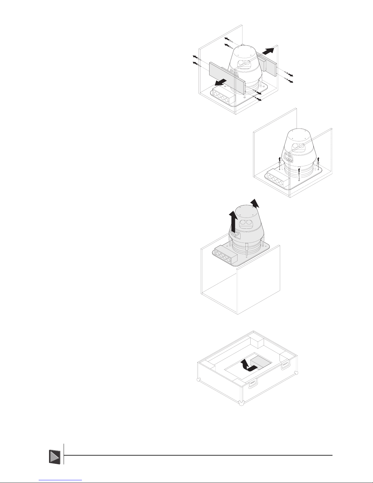
5 Using a crosshead
screwdriver, remove the
eight screws securing
the lid onto the inner
box and remove the lid.
ïRemove the flight case lid
òLift out the inner box
ïRemove the inner box lid
5CyScan Positioning System • Installation and Maintenance Guide r1.1
GC S
GC S
6 Using a crosshead
screwdriver,
remove the eight
screws securing
the two end
bumper boards
and remove.
7 Using a 13mm socket and ratchet,
remove the four bolts that secure the
CyScan sensor to the base of the inner
box.
8 With the assistance of
another person, lift the
sensor from the inner
box using the two
carrying handles. Place
the sensor next to the
pre-installed mounting
plate on deck.
9 From the access hole in
the base of the flight
case, remove the
power supply and data
converter boxes plus
their accompanying
cables.
The system is now ready for
installation.
ïRemove the bumper
boards
ñRemove the bolts
ïLift out the sensor
ïRemove the
peripheral items

6CyScan Positioning System • Installation and Maintenance Guide r1.1
GC S
GC S
Mounting the System Components
The sensor can be mounted on the vessel using four bolts. The bolts secure the sensor
unit through the holes in the base.
!Warning: The CyScan Sensor weighs approximately 30kg. Two people, using the
integral handles on either side, should perform all lifting and carrying of the
unit.
To mount the CyScan Sensor:
1 With the assistance of another person,
use the two lifting handles to lift the
CyScan Sensor onto the required
mounting plate.
2 Orient the CyScan Sensor so that its
four connectors face the Stern of the
vessel.
3 Carefully lower the CyScan Sensor onto
the mounting position so that its four
mounting holes lineup with those of the
pre-drilled mounting plate. Refer to
Appendix 2 for mounting details.
4 Insert four M8 x 25 stainless steel bolts
and tighten them evenly using a 13mm
socket and ratchet.
STERN
Refer to Appendix 2 for
CyScan Sensor mounting
template details.
5 Remove each of the four locking pins
from the sensor. Ensuring that the white
bellows are not damaged, rotate the
larger barrel of each locking pin clockwise
until it becomes short enough to remove.
Keep the locking pins with the flight case
for future shipping. Avoid using tools for
this job to minimise the chance of inad-
vertently tightening the locking pins and
damaging the CyScan Sensor.
!Important: Ensure that the CyScan Sensor has a clear view in the intended
direction of the mooring point targets. Also, there should be no object within
300mm of the rotating head in any direction as the head requires sufficient space
to tilt in response to pitch and roll vessel movements.
When mounting two CyScan sensors on the same vessel
In situations where two separate CyScan sensors are to be used on the same vessel, the
following criteria should be met:
• The two CyScan sensors must be mounted at least 20m apart.
• An opaque screen should be mounted between the two sensors to avoid crossover
of laser beams.
• The blanking zones of both units should be set so that the alternate sensor is
excluded from the zone of operation.

7CyScan Positioning System • Installation and Maintenance Guide r1.1
GC S
GC S
To mount the CyScan PSU:
The CyScan PSU must be securely mounted within
one metre of the CyScan Sensor position.
1 Prepare a suitable site for the PSU and
pre-drill pilot holes for the mounting screws
according to the template provided in
Appendix 3.
2 Remove the PSU lid and insert four M6 x
30 stainless steel cap head screws through
the mounting holes at the four corners of
the PSU enclosure.
To mount the CyScan Data Converter
The CyScan Data Converter must be securely mounted in the vicinity of the CyScan
notebook computer.
1 Prepare a suitable site for the Data Converter and pre-drill pilot holes for the
mounting screws according to the template provided in Appendix 4.
2 Remove the Data Converter lid and insert four M4 x 20 stainless steel cap head
screws through the mounting holes at the four corners of the Data Converter
enclosure.
8CyScan Positioning System • Installation and Maintenance Guide r1.1
GC S
GC S
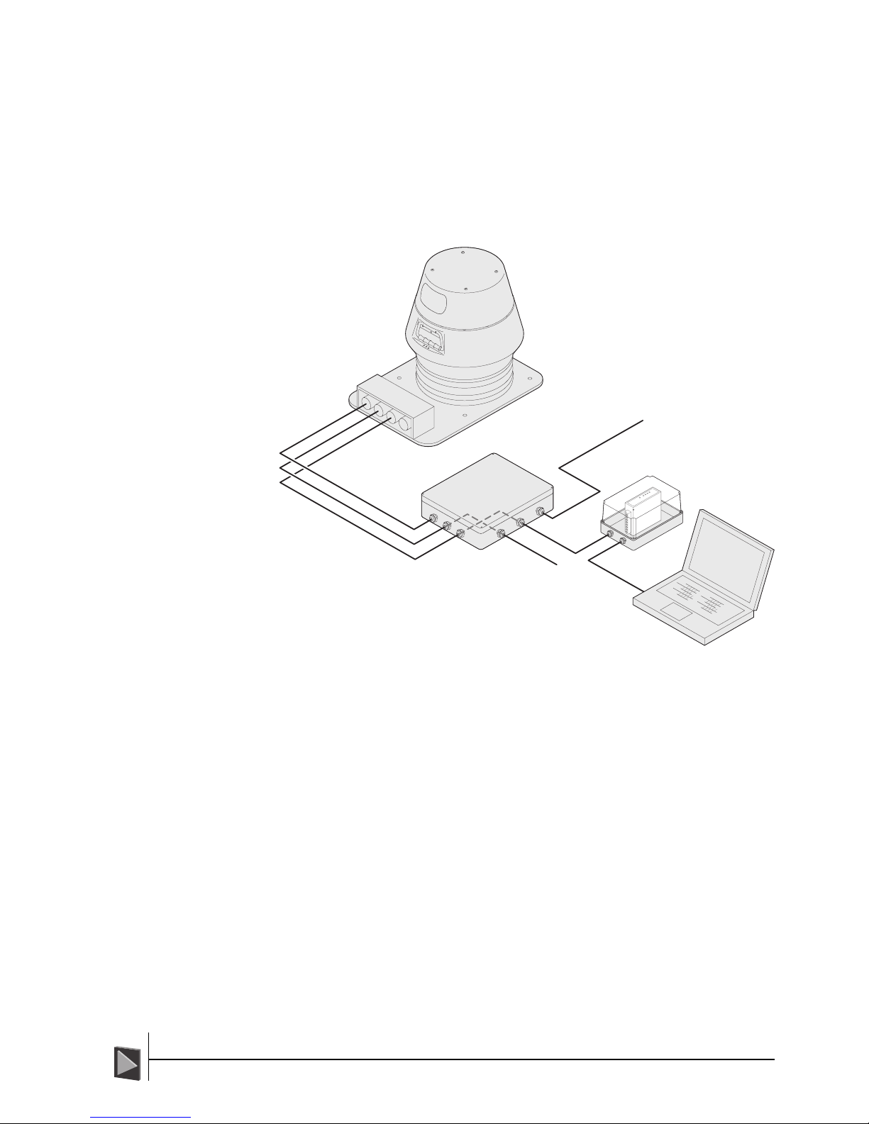
Wiring the CyScan System
The CyScan system introduces four main items to the vessel, these are:
• CyScan Sensor
• Power Supply Unit
• Data Converter
• CyScan Console Notebook Computer
The diagram below indicates the connections between the four items.
1
2
3
4
5
6
7
8
9
10
11
12
3
13
14
15
16
17
18
19
20
21
3
22
22
22
22
23
23
23
23
3
Console
DP
Power
2TX
2RX
1TX
1RX
PWR
Power
CyScan
Sensor
Power
Supply
Unit Data
Converter
DP Feed
Console Feed
To
DP Unit
Main
Power In
CyScan
Console
notebook
computer
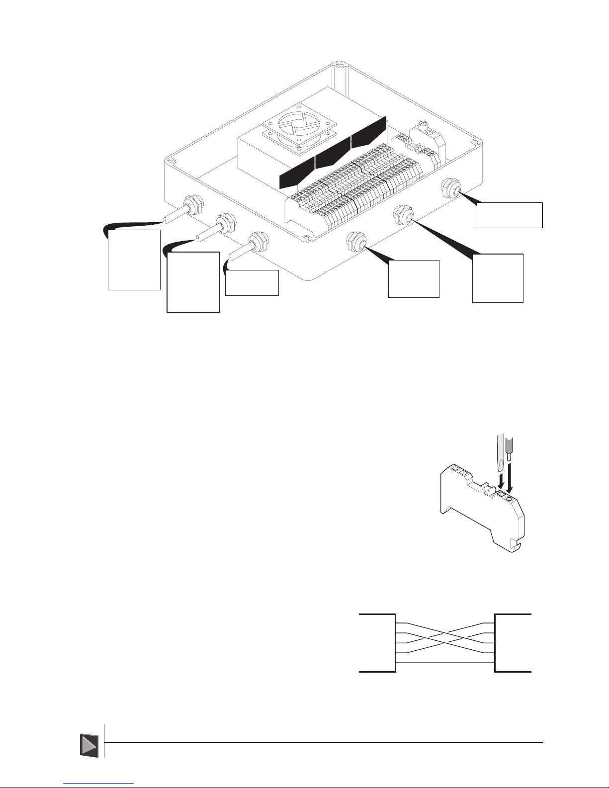
Power Supply Unit (PSU)
The PSU is supplied with three flying leads, all of which attach to the connectors at the
Stern end of the sensor. Three M20 x 1.5 threaded holes (fitted with stopping plugs) are
provided to accommodate cable glands leading to/from:
• The vessel’s DP system
• The CyScan notebook computer (via the Data Converter)
• A suitable AC power feed
Inside, the PSU contains a row of industrial connectors to make the wiring process as
quick and flexible as possible. Each connector is numbered and the relevant signal con-
nections (with their connector number) are shown on the diagram (overleaf). The PSU
requires a supply of 90-264VAC at 5A.
9CyScan Positioning System • Installation and Maintenance Guide r1.1
GC S
GC S
Power Supply Unit (continued)
!IMPORTANT: 0V is not the same as GND. 0V is the power supply return whereas
GND is a digital ground connection for the communication ports. If 0V and GND
are crossed or joined, the system will not function correctly.
!IMPORTANT: When replacing the lid on the PSU, ensure that the rubber seal is
smeared with silicone grease (Dow Corning® DC4) to maintain a watertight fit.
To insert wires:
!WARNING: Ensure all power is removed from the
system before altering any wiring.
1 Push a small flatblade screwdriver into the square
vertical hole at the front of the connector block
and press down on the lever inside.
2 While pressure is applied to the screwdriver, insert
the required wire(s) into the round hole adjacent to
the square hole.
3 Remove the screwdriver. Check that the cable is
securely held in place.
DP Signal Crossover
The RS485 connection between the
CyScan PSU and the vessel’s DP
system requires a crossover in order
that transmit and receive signals are
correctly routed. Ensure that the
crossover is correctly performed as
the cable from the DP system is
wired into the PSU.
1
2
3
4
5
6
7
8
9
10
11
12
3
19 18 17 16 15 14 13
20
21
3
23 23 23 22 22 22 22
23
3
Console
DP
Power
Power Input
90-264VAC 47-63Hz
0V AC
Earth
Conn.
1
2
3
Signal
RXA
TXB
TXA
RXB
GND
Connector
20
19
18
17
14
DP
OV
RXD+
TXD-
TXD+
RXD-
24V
Link GJ
GND
Link GJ
Cable Socket
A
B
C
D
E
F
G
H
J
Console
OV
RXD+
TXD-
TXD+
RXD-
24V
Link GJ
GND
Link GJ
Cable Plug
A
B
C
D
E
F
G
H
J
Power
Earth
24VDC
GND
Cable Socket
C
A
B
Signal
0V
24VDC
GND
RXA
TXB
TXA
RXB
Connector
23
22
11
10
9
8
5
Console Signals
(To Data Converter)
DP Connection
Main AC Power Input
3
RXA
TXB
TXA
RXB
GND
RXA
TXB
TXA
RXB
GND
CyScan
PSU
Vessel
DP System

10CyScan Positioning System • Installation and Maintenance Guide r1.1
GC S
GC S
The Data Converter
The Data Converter is necessary to translate between the RS485 signals used by the
CyScan sensor (and the DP system) and the RS232 signals used by the notebook compu-
ter. The Data Converter is contained within a watertight enclosure, however, it is usually
mounted on the bridge near to the CyScan notebook (refer to mounting template in
Appendix 4). The Data Converter requires a DC power supply between 7 and 35V – this
can be derived either from the CyScan Power Supply Unit or from the vessel’s bridge, as
required.
2TX
2RX
1TX
1RX
PWR
Signal
TX
NC
RX
NC
RTS
GND
7-35VDC
OV
Connector
1
2
3
4
5
6
7
8
Signal
GND
NC
RXB
RXA
TXB
TXA
Connector
6
5
4
3
2
1
DIP Switch
1
2
3
4
Position
OFF
OFF
ON
OFF
CyScan Notebook &
Power Connections
Console Signals
from PSU Unit
Data Converter Signal Crossover
The RS485 connection
between the CyScan PSU
and the Data Converter
requires a crossover in order
that transmit and receive
signals are correctly routed.
Ensure that the crossover is
correctly performed as the
cable from the Data Con-
verter is wired into the PSU.
RXA
TXB
TXA
RXB
GND
RXA
TXB
TXA
RXB
GND
CyScan
PSU
Data
Converter
The Data Converter is supplied with a single cable 2 metres in length that has a 9 pin
female D-Type connector for attachment to the CyScan notebook computer’s serial port.
A second cable gland allows entry for a cable to connect with the CyScan Power Supply
Unit.
otebook computer
The CyScan notebook computer is supplied with a battery charger and mains plug. This
should be connected when in use. A footprint of 400 x 400 mm should be allowed for
the console notebook computer. The notebook charger is typically 200 x 70 x 50mm and
will require mounting close to a mains supply.
11CyScan Positioning System • Installation and Maintenance Guide r1.1
GC S
GC S
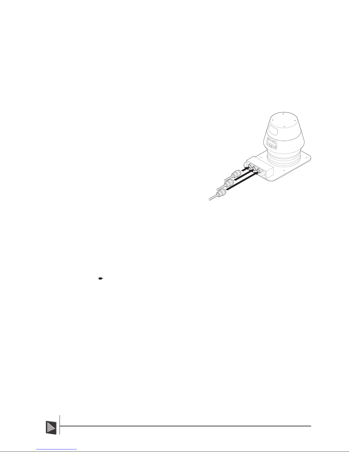
Connecting the CyScan Sensor
With the CyScan Sensor in position, the necessary electrical connections can be made.
!Important: The Console application must be closed whilst the Sensor is being
connected or disconnected.
To connect the CyScan Sensor:
1 Remove the protective dust caps from the Power, DP and Console sockets at the
Stern end of the CyScan Sensor. Do not remove the protective cap from the fourth
sensor connector.
The cable connectors and corresponding sockets are similarly labelled. Also, the
sockets and connectors are not interchangeable.
!Warning: The scanning head will begin to spin
within 30 seconds after power is applied.
Ensure that it is not obstructed before attach-
ing the power connector. Keep all objects at
least 300mm away from the scanning head
in all directions.
2 Attach each of the three cable
connectors, in the order that
follows, to the appropriate
sockets on the CyScan
sensor:
1 First, attach the
Power connector.
2 Next, attach the DP
Feed and Console connectors.
For each connection:
• Match the orientation of the cable connector to the socket (position 1 on
the connector should be facing upwards) and push it into the socket until
resistance is detected.
• Next, push the outer ring of the cable connector until it locks in place.
3 Double check that each connection is secure.
Note: For pin-outs of all sensor connectors, refer to Appendix 1.
DP Feed
Console
Power

12CyScan Positioning System • Installation and Maintenance Guide r1.1
GC S
GC S
Red
Yellow
Green
Leveller diagnostic
Embedded PC status
Main heartbeat
CyScan LED Indicators
To provide instant status information, the CyScan sensor features three LED indicators
mounted beneath the carrying handle at the Stern side. Each indicator displays the
current status of three key elements of the sensor circuitry:
Correct startup indication
As the CyScan sensor initialises itself, the following sequence should be seen:
Red Flashes once briefly when power is applied and should then be off for as
long as the yellow LED is on. As soon as the yellow LED has turned off, it
will toggle at one second intervals as the leveller circuitry initialises for about
30 seconds. After the initialisation period, the Red indicator should switch
off and stay off. If at any point it stays on permanently then a hardware
fault has been detected.
Yellow On continuously after power has been applied while the embedded PC
circuitry initialises. After the initialisation period, the Yellow indicator should
switch off and stay off. It will come on again once the system has been
shutdown or in case of an embedded PC failure.
Green Toggles twice a second after power is applied and while the yellow led is on. As
soon as the yellow led switches off and the leveller initialises (RED led toggles),
the green led will begin to flash at 10 Hz intervals giving the main system
heartbeat. When the system is suspended it flashes briefly once a second.
Error states and possible causes
Red Permanently on at any point - Electronic hardware failure within the leveller
or sensor circuitry. Can also come on when a hardware failure is detected
during operation.
Yellow On after the initialisation period is complete - Embedded PC failure or unit is
shut down. Communication with the sensor is not possible. Recycle power
to the CyScan system.
Green Permanently on or off - No heartbeat to the system. No operation is possi-
ble. Recycle power to the CyScan system.
Blinking slowly - unit suspended or shutdown (see YELLLOW and RED leds).
Toggling twice a second - after power has been applied, waiting for the PC
to initialise and the yellow LED to turn off.
Shutdown/suspend
Red Off unless there is a hardware failure.
Yellow On for shutdown, Off for suspend.
Green Flashes briefly once a second.
13CyScan Positioning System • Installation and Maintenance Guide r1.1
GC S
GC S
CyScan Removal
Decommissioning the CyScan system ready for stowage involves three basic stages:
• Switching off the CyScan Console System,
• Disconnecting the CyScan Sensor, and
• Un-mounting the CyScan Sensor
Switching off the CyScan Console System
!Important: The system running the CyScan Console application MUST be
switched OFF before the CyScan Sensor is disconnected.
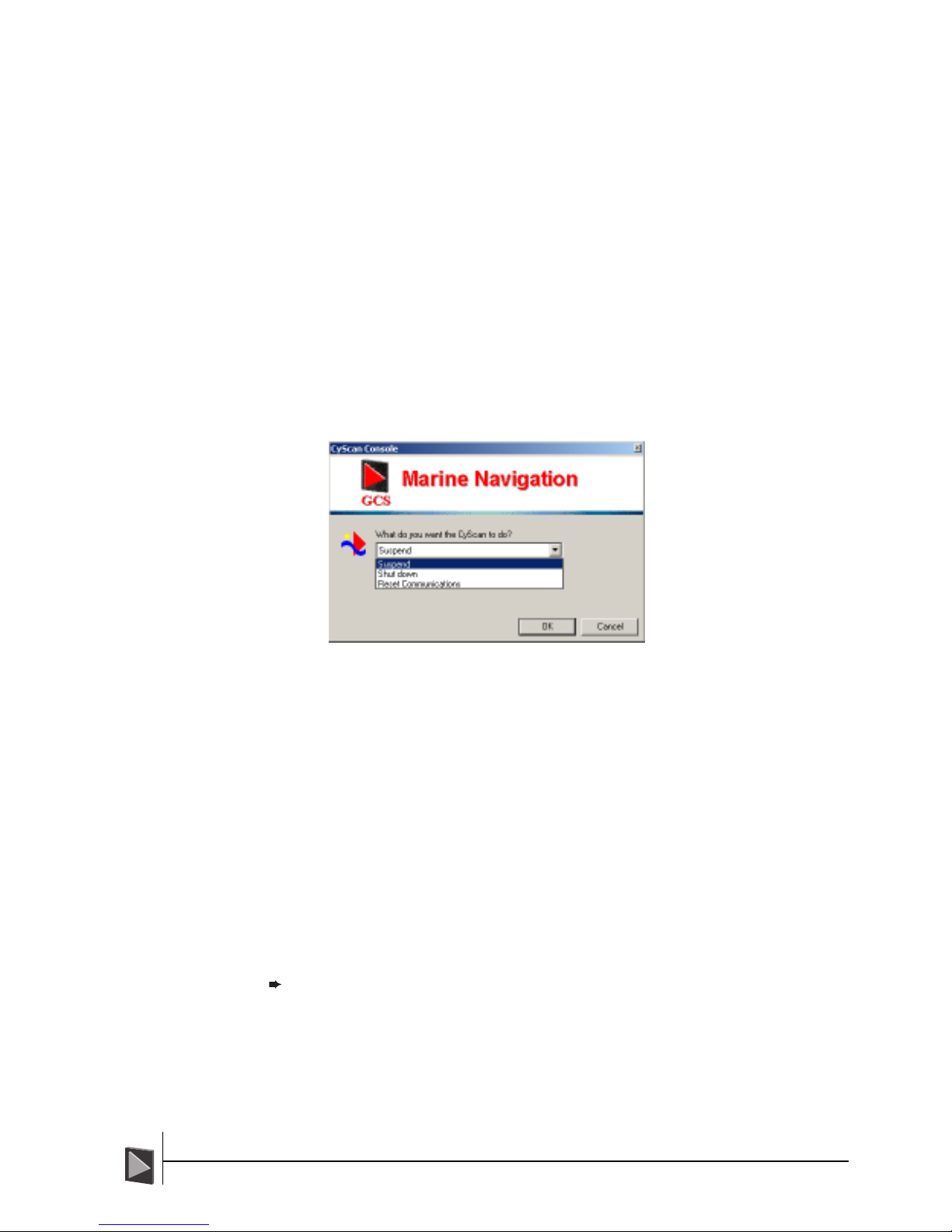
To exit CyScan Console and shutdown the system
1 Click the ‘CyScan’ button in the lower left corner of the screen (this button is
unavailable while navigating). The control dialog will be displayed:
2 Click the down-arrow to reveal the three options. Select ‘Shut down’ and click the
OK button.
3 Click ‘Yes’ to confirm your selection in the subsequent pop-up message. The
application will send shut down commands to the CyScan sensor and then close
itself down.
4 In the lower left hand corner of the Windows screen, click the Start button.
5 Select the Shut Down option.
6 In the subsequent Shut Down Windows dialog, ensure that Shut Down option is
selected and click OK.
7 When the system reports that it is ‘safe to switch off your computer’, turn off the
notebook computer.
You can now proceed to disconnect and un-mount the CyScan Sensor (if required).
The status LEDs on the sensor unit should show the yellow LED on and the green LED
flashing briefly once a second.
Note: The Console application should always be running when the Sensor is in
operation.

14CyScan Positioning System • Installation and Maintenance Guide r1.1
GC S
GC S
Disconnecting the CyScan Sensor
!Important: The system running the CyScan Console application MUST be
switched OFF before the CyScan sensor is disconnected.
!Important: Do not disconnect the sensor if the scanning head is still spinning.
To disconnect the CyScan Sensor:
1 Begin by disconnecting the DP Feed and Console connectors.
For each connection:
• Pull the outer ring of the cable connector until it disengages from the socket.
• Next, gently pull the cable connector from the socket.
2 Now disconnect the Input Power connector.
3IMPORTANT: Replace the protective dust caps onto the three sockets on the
CyScan Sensor and also on the three cable connectors.
Un-mounting the CyScan Sensor
!Warning: The CyScan Sensor weighs approximately 30kg. Two people, using the
integral handles on either side, should perform all lifting and carrying of the unit.
To un-mount the CyScan Sensor:
1 Locking pin installation:
a Locate the four anodised locking pins that
were supplied with the CyScan sensor.
b Rotate the larger barrel of each locking pin
clockwise so that they become short
enough to be inserted between the base
plate and the middle body of the sensor.
c Ensure that the scanner head is parallel with
the Sensor baseplate. Locate the four locking pin holes in the sensor base
plate holes which are adjacent to each of the four larger mounting holes.
d For each of the four locking pins, insert the point of the thinner barrel into
the locking pin hole of the base plate. Then, push the larger barrel towards
the white bellows and gently rotate the larger barrel anti-clockwise so that
the pin extends.
Important: Ensure that the white bellows are not damaged by the locking
pin rotation.
e Continue rotating the larger barrel and guide the point of the locking pin
into the corresponding hole in the underside of the sensor body (the hole
will be directly above the one on the base plate).
f Do not tighten fully until all four locking pins are in place, and then tighten
them evenly by hand so that the sensor body is fixed in a level position.
IMPORTANT: Do not use tools to tighten the locking pins.
2 Using a 13mm socket and ratchet, remove the four
mounting bolts.
3 With the assistance of another person, use the two
lifting handles to lift the sensor away from the mount-
ing plate.
4 If necessary, place the sensor in its storage case
(covered next).
15CyScan Positioning System • Installation and Maintenance Guide r1.1
GC S
GC S
acking the CyScan System
With sensor disconnected and removed from its mounting plate, you can now begin to
pack it ready for shipping.
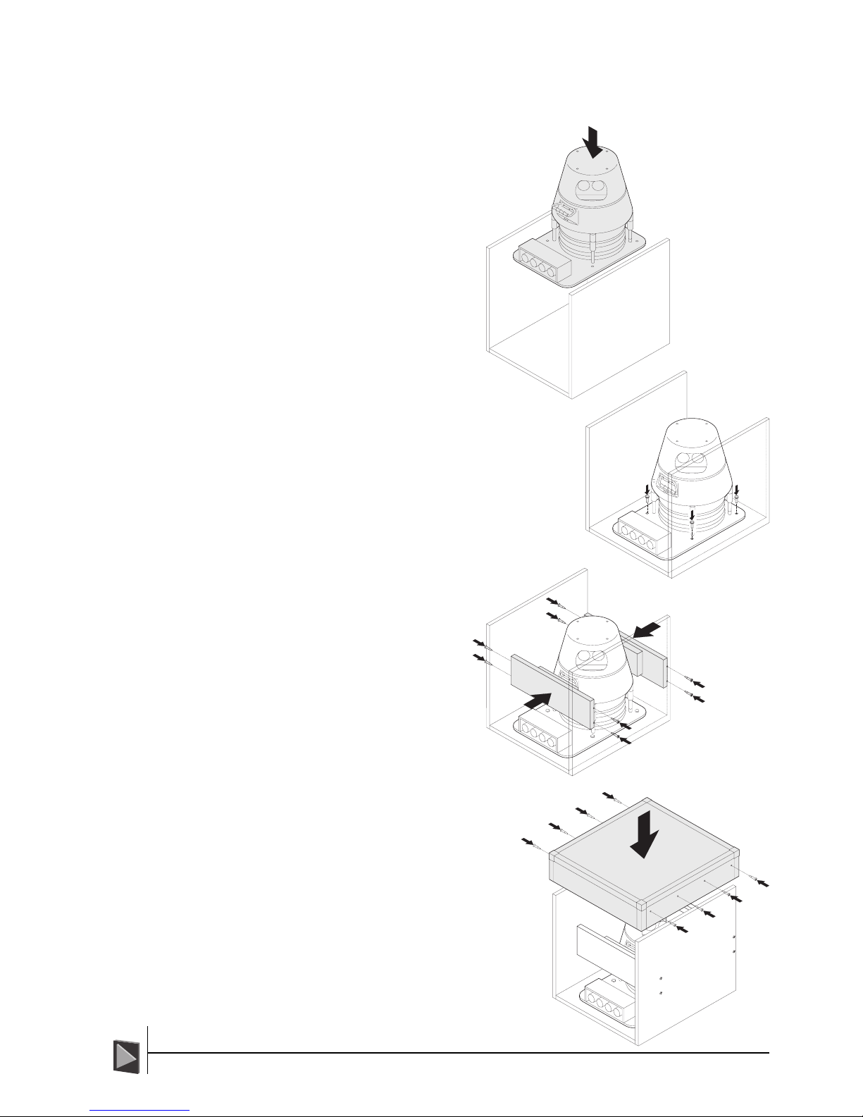
1 Locate the base and sides of
the wooden inner box in
which the CyScan sensor
was supplied. With the
assistance of another
person, lift the sensor into
the base of the inner box so
that the mounting holes of
the sensor base plate
correspond to the four
threaded inserts in the base
of the box.
2 Insert the four locking bolts. Using a 13mm
socket and ratchet, tighten the four bolts so
that the sensor is secure.
3 Locate the two end
bumper boards and
place them either side of
the sensor so that they
line up with correspond-
ing holes in the sides of
the box. The foam pads
on each of the bumper
boards should face
towards the sensor.
Insert the four screws
that secure each board
through the sides of the
inner box and tighten
with a crosshead screwdriver.
4 Place the lid of the inner box onto
base and sides and insert the
eight securing screws. Tighten the
eight screws using a crosshead
screwdriver.
16CyScan Positioning System • Installation and Maintenance Guide r1.1
GC S
GC S
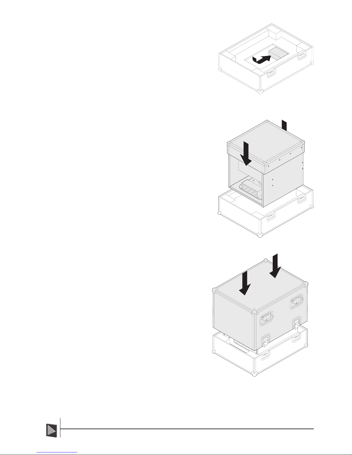
5 Locate the base of the CyScan flight
case. If the power supply and data
converter boxes are also to be
shipped, places these and their cables,
if necessary, into the lower recess of
the flight case base.
6 With the assistance of another person,
hold the open sides of the inner box
lid and lift the whole assembly into
the flight case base. Ensure that the
inner box is properly seated within the
foam guides of the flight case base.
7 With the assistance of another
person, place the lid of the flight
case onto the base so that it seats
correctly.
8 Engage the four locking catches
with the locking lips of the base
and secure each of the locking
catches by rotating the butterfly-
wing tabs clockwise.
The CyScan system is now ready for shipping.
17CyScan Positioning System • Installation and Maintenance Guide r1.1
GC S
GC S
Maintenance and Servicing
The CyScan sensor is constructed from distinct modules that can be removed and re-
placed as required. This section covers the removal, replacement, upgrading and servicing
of the CyScan sensor system. A list of recommended spare parts is listed in Appendix 5.
Removing and fitting key components
There are nine key stages of disassembly/assembly for all CyScan sensor modules, these
are:
Stage Previous stages required
1The Rotor Heatshield
2The Rotor 1
3The Body Cover 1
4The Motor Gearbox 1,2,3
5The CPU Module 1,3
6The Controller Board 1,3,5
7The Yaw Gyro 1,2,3,4,5,6
8The Vertical Reference Unit (VRU) 1,2,3,4
9The Pitch and Roll Actuators 1,2,3,4
The figures shown to the right of each stage are the other previous stages that you must
complete before access can be gained to the necessary components.
!WARNING: Ensure Static Safe Handling procedures are observed when removing/
fitting circuit board assemblies, e.g. CPU & Controller PCB, VRU, Yaw gyro, etc.
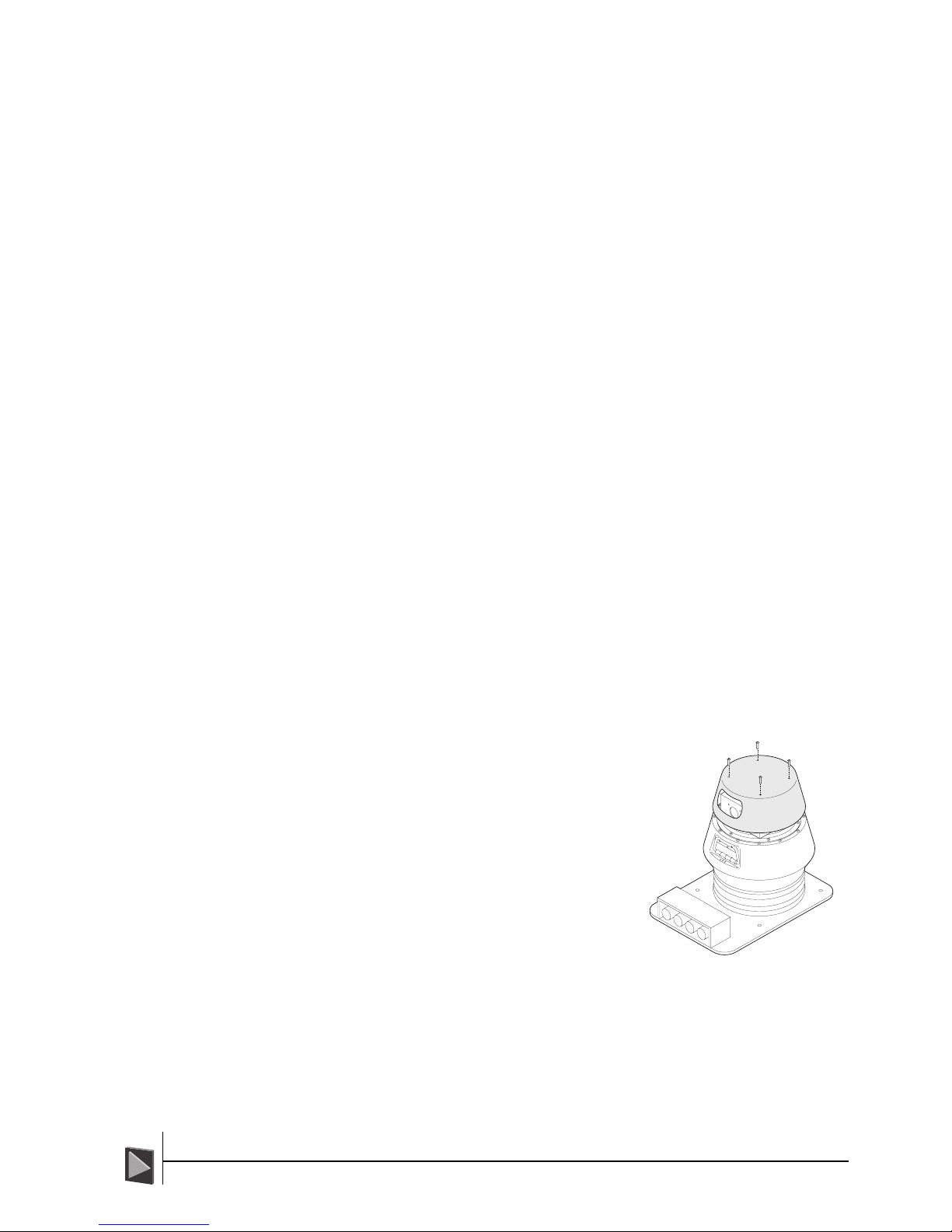
Stage 1 - The Rotor Heatshield
To remove the Rotor Heatshield:
1 Using a flat blade screwdriver, remove the
four screws on top of the rotor heatshield.
2 Lift the rotor heatshield up away from the
sensor.
To fit the Rotor Heatshield:
1 Place the rotor heatshield onto the rotor so
that the aperture aligns with the two rotor
lenses. Also the four mounting holes must
correspond to the four pillars on top of the
rotor.
2 Insert M5 x 12 slotted screws and bonded
seals into the four mounting holes and
using a flat blade screwdriver, tighten the
four screws in a staged and even manner
until all are tight.

18CyScan Positioning System • Installation and Maintenance Guide r1.1
GC S
GC S
Stage 2 - The Rotor
To remove the Rotor:
1 Using a flat blade screwdriver, loosen the two
screws on top of the rotor in an even manner
until they are both loose. Fully undo the two
screws and retract them from the rotor.
!IMPORTANT: Both screws have special
waterproof ‘bonded seal’ washers. Be
sure to keep the washers safe with the
screws. Standard washers must not be
used in replacement, as a watertight seal
will not be achieved.
2 Lift the rotor vertically upwards away from the
sensor gearbox.
To fit the Rotor:
1 Ensure the ‘O’ ring is present on the top of the gearbox shaft. Smear silicone
grease lightly over the ‘O’ ring but ensure none gets on the contacts of the ex-
posed connector.
2 Orient the rotor above the sensor with its main connector facing down to the
sensor and the face with the large
connector pointing in the same
direction as the small key screw
on the shaft. This ensures that the
keyway in the rotor connector
aligns with the key screw of the
shaft.
3 Place the rotor onto the shaft and
slide it down into position. It may
be necessary to rock the rotor
slightly to get it to fully mate with
the shaft.
4 Insert the two long M5 x 100
screws each with a specialist
waterproof sealing washer intact.
Smear silicone grease onto the
sealing washers for better water
protection. These bonded seal washers are essential to form a watertight seal -
normal washers must not be used in replacement.
!IMPORTANT: It is essential that the two screws in the next step are tight-
ened evenly.
5 Using a flat blade screwdriver, tighten the two screws alternately to take up the
slack. Now tighten the two screws alternately in decreasing steps of rotation, i.e.
one turn each, then three quarters each, then half each, etc. Continue in small
increments of rotation until both are brought to even tightness. Finally, apply a
coating of silicone grease around the screw heads and sealing washers to minimise
the chance of water ingress at this point.
6 Ensure that the rotor can rotate freely without touching any part of the sensor
gearbox.
Table of contents
Popular Control System manuals by other brands

Lipper
Lipper Sway Command 1.5 Installation and owner's manual

VIPA
VIPA System 200V CP 240 manual

Douglas Lighting Controls
Douglas Lighting Controls LitePak WPAK-33518-S Technical data

auer
auer Thorix EVOLUTION 2C Installation and operating instructions

Digitrax
Digitrax DS78V instructions

Eurotherm
Eurotherm PC300 Installation manual and user's guide

Whelen Engineering Company
Whelen Engineering Company CenCom Sapphire installation guide

Carel
Carel infrared IR32CE Series user manual

Intellitec
Intellitec iConnex user manual

Triple Plus
Triple Plus CLM-COAMAP-1-02 quick start guide

YASKAWA
YASKAWA VIPA System 300S manual

Lutron Electronics
Lutron Electronics VISEO GRAFIK5000 Operation manual


