BENDIXKing Skymap IIIC Manual

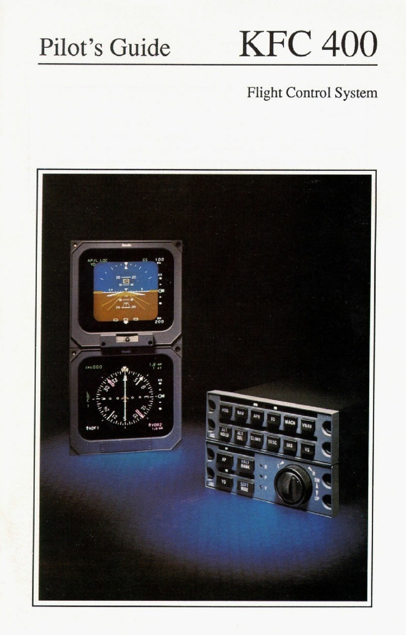
KFC 500
Pilot’s Guide
Bendix/King®
Flight Control System
Honeywell International Inc.
One Technology Center
23500 W. 105th Street
Olathe, Kansas 66061
FAX 913-791-1302
Telephone: (913) 712-0400
Copyright ©1993 Honeywell International Inc.
All rights reserved.
006-08750-0000
Rev. 0 Sept/93 N
006-08750-0000 September 1993

1
Introduction
The KFC 500 Automatic Flight
Control System combines complete
autopilot and flight director computa-
tion functions in a single computer.
Its digital flight computer and inte-
grated architecture enable the KFC
500 to determine helicopter control
requirements sooner, and to execute
them with greater smoothness and
accuracy than previous autopilot sys-
tems.
Due primarily to its dual channel
flight computer design, the KFC 500
can more positively control the air-
craft while providing a level of safety
monitoring unavailable with single
channel systems. Digital, solid-state
design throughout the Flight Control
System provides maximum reliability
while economizing on system weight
and required installation space.
The KFC 500 is designed to
optimize passenger and flight crew
comfort, while still providing accurate
control response in any flight situa-
tion. Wherever possible, autopilot-
induced aircraft motions border on
the lower limits of human perceptibil-
ity, ensuring exceptionally smooth
flight. Many of the Flight Control
System’s maximum commandable
values were determined for the Bell
Model 230 during the aircraft certifi-
cation process.
The KFC 500 is integrated with
KAD 480 Central Air Data System
and the EFS 40/50 Electronic Flight
Instrument System to enhance user-
friendliness as well as system
annunciation.
Internal safety monitors and
automatic self-test functions keep
constant track of the KFC 500’s sta-
tus, and provide signals for auto-
matic shutdown of impaired control
axes or flight director functions.
When the KFC 500 decouples an
autopilot axis it both releases the
affected servo brake and shuts off
motor drive power, providing dual
layers of protection against servo
overcontrol.
In addition to reliability and light
weight, the KFC 500 is designed to
be easy to maintain in the field. Self-
contained diagnostic tests assist
troubleshooting done by mainte-
nance personnel at Bendix/King®
factory-approved service centers.
The EFIS interface provides addi-
tional trouble-shooting access via the
cockpit display units. The Built-In-
Test functions enable a technician to
trace a fault to the individual circuit
board, or external sensor con-
cerned. Circuit boards inside remote-
mounted components are installed
vertically, to prevent condensation
pooling. Qualified Bendix/King®ser-
vice centers around the world are
ready to provide assistance when-
ever necessary.
The KFC 500 is integrated to the
EFS 40/50 Electronic Flight
Instrument System allowing a very
flexible navigation system interface.
All of the KFC 500’s digital interfaces
are based on ARINC 429 specifica-
tions, and analog/digital converters
are supplied wherever necessary to
provide the greatest interface versa-
tility.

2
Important:
This Pilot's Guide provides a general description of the
various operational characteristics of the KFC 500 Flight Control
System. However, operation of the system should not be
attempted without first reviewing the applicable FAA Approved
Rotorcraft Flight Manual Supplement for complete system
familiarization and operating limitations.

3
Introduction............................................................................................1
System Components.............................................................................5
System Description
Normal Flight Control Operations
KMS 540 Flight Director Mode Select Panel ....................................8
Basic Flight Director Mode ...............................................................8
Pitch Attitude Hold/Roll Attitude/Heading Hold.................................9
Lateral Command Control ................................................................9
Vertical Command Control .............................................................10
Force Trim Release........................................................................11
Navigation Standby ........................................................................11
Go-Around......................................................................................11
Yaw Force Trim Release................................................................12
Yaw Trim .......................................................................................12
KMS 540 Lateral Mode Selection
Heading (HDG)...............................................................................13
Bank Angle Limit (BL).....................................................................13
Navigation (NAV)............................................................................14
Approach (APR) .............................................................................14
KMS 540 Vertical Mode Selection
Altitude Select (ALT SEL)...............................................................16
Altitude Hold (ALT HOLD) ..............................................................16
Indicated Airspeed (IAS) ................................................................17
Vertical Speed (VS)........................................................................17
KMS 540 Autopilot and Yaw Damper Mode Selection
Yaw Damper (YD) ..........................................................................19
Autopilot (AP) .................................................................................19
KFC 500 Equipment Descriptions
KSA 572 Trim Actuator...................................................................20
KLA 570 Linear Actuator ................................................................20
KVG 350 Attitude Gyro...................................................................20
KCS 305 Slaved Compass System................................................21
KRG 332 Yaw Rate Gyro ...............................................................21
KAB 330 Triaxial Accelerometer ....................................................21
Control Position Transducer...........................................................21
Autopilot/EFIS Switches Descriptions
KCP 520 Flight Computer ..............................................................22
Autopilot/EFIS Master ....................................................................22
CMPST...........................................................................................22
VG SEL 1-2 ....................................................................................23
Table of Contents

4
DG SEL 1-2 ....................................................................................23
DME HOLD ....................................................................................23
VG FAST ERECT...........................................................................23
Cyclic Grip Switch Assembly..........................................................24
Collective Switch Assembly............................................................25
Basic EFS 40 Description
ED 461 EFIS Display......................................................................26
EFS 40 Display Units .....................................................................27
KAD 480 Air Data System
KDC 481T Central Air Data Computer ...........................................32
KAV 485 Altitude/Vertical Speed Indicator .....................................34
Emergency Procedures ......................................................................39
Preflight Procedures ...........................................................................43
Operational Examples
Attitude Hold...................................................................................48
Navigation Standby ........................................................................48
Force Trim Release........................................................................48
Heading Select ...............................................................................49
Go-Around Mode............................................................................50
Navigation Coupling .......................................................................50
Yaw Force Trim Release................................................................51
Yaw Trim ........................................................................................51
Takeoff and Climb ..........................................................................52
Front Course ILS Approach ...........................................................54
Go-Around from an ILS Approach..................................................56
Localizer Back Course Approach ...................................................58
Performance Specifications ...............................................................62

5
ı
2020
10 10
2020
10 10
33 N 3
GS
AZ GS 500
RA
DH
200
F
S
KDM 706A
ı
1
KDC 481
ı
2020
10 10
2020
10 10
33 N 3
GS
AZ GS 500
RA
DH
200
F
S
0
2
3
4
5
6
7
8
9ALT
VS ALT
1000 FT/MIN
VS
2
4
6
6
4
21
1
.5
.5
0
UP
DN
IN HG MB DEN ALT
SEL
ALERT
ALT
VS
1,160
30.08 1,690
1
1
ENG SEL
BARO
U
P
S
H
E
T
S
T
SEL
U
P
L
L
V
S
KCP 520
ı
KAV 485
KVG 350
KRG 332
YAW RATE GYRO
KCP 520
FD/AP
COMPUTER
SG 465
KMS 540
AP/FD
MODE SELECTOR
KDC 481T
AIR DATA
COMPUTER
SG 465
ı
ı
KRG332
RATEGYRO
ED 462
ED 461
ı
HDG NAV APR BL
ALT VS IAS
FD
AP YD
KSG 105
KSG 105
1
KSA 572
KLA 570
VG
FAST
ERECT
VG SEL
1 2
DME
HOLD
DG SEL
1 2
CMPST
TST
BRT
1
2
1
SYNC
REF
DIR
N
A
V
A
R
C
H
S
I
ADF 2
M
L
S
1
23
AZ
359
12.
6
NM
N
33
30
W
24
2
1
S
1
5
1
2
E
6
3
11.
5
11.
5
G
S
VG #2
DG #2
CRSR
NAV
FPL
MODE
TRIP
CALC
STAT
SETUP
OTHER
NAV
D/T
ACTV
REF
CTR
APT
VOR
NDB
INT
SUPL
ALT CLR ENT
KLN 90
ıEMP =TOP |PRESENT POS
dddddid‹ddd|
DIS 89.4nm|BUM 300^FR
GS 180kt| 37.4NM
ETE :29| N 38^01.4'
BRG 026^| W 95^32.6'
NAV 1|enr-leg |NAV 2
GPS
BRT
D
MSG
CRSR
KLN 90/90A
SG 465
SYMBOL
GENERATOR
ED 462
ED 461
SG 465
ı
KVG 350
KSG 105
KSG 105
1
TST
BRT
1
2
1
SYNC
REF
DIR
N
A
V
A
R
C
H
S
I
ADF 2
M
L
S
1
23
AZ
359
12.
6
NM
N
33
30
W
24
2
1
S
1
5
1
2
E
6
3
11.
5
11.
5
G
S
VG #1
DG #1
KNR 634
ı
KNR 634
ı
KDM 706A DME KNR 634
VOR/ILS/MB
KSA 572
KLA 570
KSA 572
KLA 570
POSITION
SYNCHRO
POSITION
SYNCHRO
POSITION
SYNCHRO
COLLECTIVE POSITION
SYNCHRO
CYCLIC
SWITCHES
VG
FAST
ERECT
VG SEL
1 2
DG SEL
1 2
CMPST
AP FAIL
TRM FAIL
DIRECTION
OFFLIGHT
KAB 330
ACCELEROMETER
PITCH
ROLL
YAW
KFC 500 SYSTEM BLOCK DIAGRAM
FOUR TUBE EFS 40 SYSTEM

6

7
KFC 500
Normal Operation

8
KMS 540 Flight Director Mode Select Panel
a new altitude in Altitude Select,
does not affect active tracking modes
such as Heading or Vertical Speed
Hold. It is often useful to engage a
separate mode to provide flight guid-
ance to the capture point for a
course or altitude selected in an Arm
mode. The Flight Control System
will transition automatically to capture
the armed mode, cancelling the pre-
vious selection. Examples of this
operation are described in the
Operational Examples section of this
guide.
To cancel a flight director mode
engaged in either capture or tracking
operations, either select an alternate
tracking mode or press the engaged
mode’s pushbutton on the mode
select panel. The latter method also
cancels modes while in their Arm
phases. Go-Around is an exception.
The collective-mounted pushbutton
provides the engage function only.
When the flight director is operat-
ing with no horizontal or vertical
mode selected, the KFC 500 auto-
matically engages in Heading Hold
and Pitch Attitude Hold. These
default modes provide basic flight
stability and serve as safety backups
in the event that the flight computer
cancels an active mode due to loss
of required navigation signal or sys-
tem malfunction. Engaging the
KFC 500 in any tracking mode auto-
matically cancels the corresponding
default mode for that particular axis.
Basic Flight Director Mode
Depressing the FD button on the
Mode Select Panel will activate the
basic Flight Director. Pitch Attitude
Modes of Operation
The KMS 540 Mode Select Panel
provides control and annunciation of
the KFC 500’s Flight Director,
Autopilot, and Yaw Damper modes.
Illumination of the annunciator lamps
on the mode controller is adjusted
automatically by a photocell located
on the face of the unit. To activate
flight director or autopilot modes
using the Mode Select Panel, press
the desired pushbutton. The corre-
sponding mode lamp above the
pushbutton will illuminate and the
mode annunciation on the Electronic
Attitude Director Indicator, EADI, will
appear. Alternatively, to deactivate a
flight director or autopilot mode when
activated, depress the respective
pushbutton.
The KFC 500 will engage in only
one horizontal and one vertical track-
ing mode at a time. Flight director
modes engaged in initial, arming
sequences, however, do not conflict
with tracking operations in other
modes. For example, selecting a
new course in the Nav Arm mode, or
ı
APRHDG
ALT
BL
IAS
AP FD
NAV
VS
SCAS
Normal Operation

9
Hold and Roll Attitude/Heading Hold
automatically engage unless other
tracking modes are selected. Pitch
Attitude Hold and Roll
Attitude/Heading Hold are annunci-
ated on the EADI as PIT and ROL,
respectively.
Pitch Attitude Hold
Roll Attitude/Heading Hold
In the absence of any other
selected Flight Director Modes, the
Flight Director will provide com-
mands to maintain current pitch atti-
tude and establish a level roll atti-
tude. When roll attitude approaches
six degrees or less bank angle, the
flight director will provide commands
to maintain constant heading.
Target roll and pitch attitudes
may be selected by several methods.
Adjusting the helicopter’s attitude
manually may be accomplished by
pressing the Force Trim Release
(FTR) Switch to the first detent while
moving the cyclic (and the helicopter)
to the desired attitude. Upon release
of the FTR switch, the Flight Director
will provide commands to maintain
the target Pitch and Roll attitude.
Alternatively, Attitude Hold com-
mands may be modified by moving
the Cyclic mounted Beep Trim(CBT)
switch in the appropriate directions.
If a target roll attitude of six
degrees or less is selected, the Flight
Director will provide commands to
maintain the helicopter's current
heading. Heading information from
the KSG 305 Compass System's
Directional Gyro provides heading
informantion to the Flight
Director/Autopilot.
Selecting any horizontal or verti-
cal tracking mode cancels Roll
Attitude Hold or Pitch Attitude Hold,
respectively. Either mode may be
used in conjunction with any Arm
mode to provide flight guidance for
course or altitude intercepts.
Lateral Command Control
Activated by the Cyclic Beep
Trim (CBT) switch when the Flight
Director or Autopilot is on, Lateral
Command Control modifies the
AFCS’s reference attitude during
operations in Roll Attitude Hold.
Moving the four-way switch either
right or left cancels any selected
flight director horizontal mode and
engages Roll Attitude Hold.
Operating Lateral Command Control
does not affect Arm operations in
Nav or Approach modes, nor does it
affect flight director vertical modes,
with the exception of Glideslope,
which it cancels along with
Approach. When Lateral Command
Control is used, the aircraft will be
commanded to follow the pilot’s input
to roll left or right with a constant roll
rate until the beep trim switch is
released.
Upon release of the CBT switch,
the flight director will command the
aircraft to maintain the existing roll
FD
FTR
CBT
Cyclic Grip
Switches

10
attitude. Roll attitudes of less than six
degrees of bank will cause the Flight
Director to revert to commands for
roll-level flight with heading hold.
Activating Discrete or Continuous
Lateral Command has the following
effect upon command values in flight
director operations:
Flight Director Lateral Command Values
Discrete Command System Response
Roll Attitude Hold First Click=6°, Subsequent=1° per click
Heading Select 1° Heading Bug Movement per click
Continuous Command
Roll Attitude Hold Constant Roll Rate
Heading Select 15° Heading Bug Movement per second
Vertical Command Control
Using the same cyclic switch as
mentioned in the previous para-
graph, vertical commands can be
modified by moving the vertical com-
mand switch fore and aft. Operation
of the Vertical Command Control
depends on the flight director or
autopilot mode engaged. Moving
the switch forward adjusts the heli-
copter’s pitch attitude downward,
while moving it rearward adjusts the
attitude upward.
Activating Vertical Command
cancels certain flight director vertical
tracking modes, but has no effect on
modes engaged in the Arm phase.
The flight director will revert to Pitch
Attitude Hold if it was coupled in
Glideslope, Altitude Capture or Go-
Around at the moment of command
activation. Attitude Hold, Altitude
Hold, Indicated Airspeed Hold and
Vertical Speed Hold will remain cou-
pled throughout Vertical Command
operation.
Activating Discrete or Continuous
CBT
Flight Director Vertical Command Values
Discrete Command System Response
Pitch Attitude Hold 0.5° per click
Altitude Hold 10 feet per click
Indicated Airspeed Hold 1 knot per click
Vertical Speed Hold 100 fpm per click
Continuous Command
Pitch Attitude Hold Maintains const. acc. profile until release
Altitude Hold 50 feet per second
Indicated Airspeed Hold Five knots per second until release
Vertical Speed Hold 300 fpm per second until release

11
Vertical Command has the effect
upon command values in flight direc-
tor operations shown in the preced-
ing table.
Force Trim Release (FTR)
When the Flight Director is
active, the Force Trim Release
switch allows the crew to synchro-
nize flight director commands in pitch
and roll to the actual helicopter posi-
tion. When the selected mode for
flight director is pitch attitude hold,
altitude hold, airspeed hold, roll level
or roll attitude hold, FTR will cause a
new flight director reference to be
established upon release of the
switch. All commands will then be
directed to hold this new reference.
When the autopilot is in Attitude Hold
mode with no flight director, the
AFCS synchronizes attitude with the
present helicopter attitude when
released.
When the FTR switch is
depressed, the trim servo magnetic
brakes release, eliminating the artifi-
cial feel system, allowing the pilot
free movement of the cyclic. When
the switch is released the trim brake
re-engages. The FTR switch is dou-
ble detent. Actuation to the first
detent allows the pitch and roll
brakes to release for free cyclic
movement. Depressing through the
second detent releases the yaw
brake in addition to the pitch and roll,
allowing free cyclic and pedal move-
ment. The Force Trim System must
be “ON” for the AFCS to operate.
Navigation Standby
When the Navigation Standby
Switch on the cyclic is momentarily
depressed, the flight director deacti-
vates and the flight computer com-
mands attitude retention.
Subsequent activation of the flight
director modes may be accom-
plished by depressing the appropri-
ate Mode Select Panel pushbuttons
or by arming an altitude on the
Altitude/Vertical Speed Indicator.
Go-Around
Pressing the Go-Around
Pushbutton on the collective switch
box activates the Go-Around mode in
which the flight director commands a
750 feet per minute climb in a roll-
level attitude. Any horizontal tracking
mode may be subsequently reen-
gaged without cancelling the Go-
Around climb.
NAV
Standby
Go-
Around
FTR

Yaw Force Trim Release
A Collective mounted Yaw Force
Trim Release is provided.
Depressing this switch releases the
Yaw brake, allowing free pedal
movement when the autopilot or Yaw
Damper is engaged. Upon release of
the switch, the Autopilot/Yaw
Damper will command ball centered
flight.
12
Yaw Trim
A Collective mounted Yaw Trim
Switch is provided. Holding the
switch to the right or left moves the
Yaw Axis in the corresponding direc-
tion at a constant rate. Yaw Damper
must be operational and active for
Yaw Trim to function.
Yaw
Force
Trim
Release
Yaw
Trim

Bank Angle Limit Presentation
13
HDG (heading select)
Depressing the HDG pushbutton
on the mode select panel activates
Heading Select mode. The Heading
mode will provide flight director com-
mands to track the heading bug on
the EHSI. The heading lamp on the
mode select panel illuminates and
“HDG” is displayed on the EADI
when the heading select mode is
activated. Activating Heading Select
cancels any other lateral tracking
mode. If the Heading Select mode is
active, depressing the HDG pushbut-
ton will deactivate the the Heading
Select mode and revert the flight
director commands to maintain a roll-
level attitude that maintains the heli-
copter's present heading, the default
mode. Flashing of the annunciator
lamp indicates loss of a sensor
required to hold the selected heading
(e.g. invalid magnetic heading,
invalid selected heading). The lamp
continues flashing until a second
push of the HDG pushbutton (pilot
acknowledgement of mode loss) or
until another lateral mode is acti-
vated.
BL (bank angle limit)
This pushbutton allows the pilot to
select the maximum commanded
bank angle to be used during the
non-approach phases of flight. The
Bank Angle Limit mode allows the
maximum commanded bank angle to
be 25°, 20°, 15°, or 10°. The value
for the Bank Angle Limit is achieved
by cycling the pushbutton until the
desired value is displayed on the
EADI. If the default value, 20°, is
selected, the selected value declut-
ters on the EADI. The default value,
20°, is obtained at power-up if no
action is taken by the pilot to select
another value.
In the coupled approach phases
of flight, bank angle limiting is dis-
abled to provide optimum flight per-
formance. When coupled with the
Approach mode Armed, all captures
are made with a maximum bank
angle of 20°. If lesser bank angles
are required, the pilot may use the
heading select mode (move the
heading bug slowly) to capture the
KMS 540 Lateral Mode Selection
HDG
TST
BRT
1
2
1
SYNC
REF
DIR
N
A
V
A
R
C
H
S
I
ADF 2
L
O
C
1
CRS
359
12.6 NM
11.
5
11.
5
G
S
N
33
30
W
24
21
S
15
12
E
6
3
360°
BL
NAVHB
BL10
HDGAP
YD
Heading Select Bug
Heading Select Knob

14
localizer and then depress the APR
pushbutton to activate Approach
Mode when tracking inbound on the
appropriate course.
When the KFC 500 is coupled to
a flight management system (FMS)
that has a composite steering com-
mand to drive the flight director (ie.
KLN 90, KNS 660), the flight man-
agement system has complete con-
trol of bank angles up to 25°. Bank
limiting when coupled to a FMS is
inhibited in this situation to prevent
poor tracking performance.
Bank Angle Limit may be
engaged in conjunction with any
flight director tracking mode.
However, it’s operation will be inhib-
ited in the Approach mode and when
coupled to a FMS.
NAV (capture and track selected
navigation sensor)
The nav lamp illuminates and “NAV”
is displayed in the lateral mode win-
dow of the EADI when the NAV or
NAV ARM mode is activated by
depressing the NAV pushbutton on
the KMS 540 Mode Select Panel.
When the NAV mode is selected by
the NAV pushbutton and course nee-
dle deflection exceeds the capture
requirements of NAV mode (greater
than 50% full scale needle devia-
tion), the NAV ARM mode is acti-
vated and allows a compatible lateral
mode to be used to intercept the
desired course or track. If the air-
craft’s deviation from the selected
course centerline is sufficiently small
(less than 50% full scale needle devi-
ation), or if the rate of closure with
the new course is sufficiently high,
the flight director initiates the NAV
Capture sequence immediately.
A flashing NAV lamp indicates
loss of a sensor required to capture
or track the selected nav (e.g. invalid
NAV, invalid selected course) and
continues until a second push of the
NAV pushbutton (pilot acknowledge-
ment of mode loss). In the event of a
sustained NAV invalid during NAV
ARM, the current lateral mode will
remain active until another mode is
selected. The NAV pushbutton may
also be used to deactivate the NAV
mode.
APR (capture and track selected
sensor with approach authority)
The approach lamp on the mode
select panel illuminates when the
approach or approach ARM mode is
activated by depressing the APR
pushbutton. Upon initial selection,
APR
TST
BRT
1
2
1
SYNC
REF
DIR
N
A
V
A
R
C
H
S
I
V
O
R
1
CRS
090
7.5 NM
010°
KT140
N
33
30
W
24
21
S
15
12
E
6
3
NAV
Selected Course Course Pointer
Course Select Knob

engages Glideslope Arm (GS ARM),
Capture and Track (GS) sequences
during ILS front course approaches.
The localizer must be captured in
order for glideslope to ARM or cou-
ple. Glideslope coupling is inhibited
during back course procedures.
Any horizontal tracking mode
may be employed during Approach
Arm phases and will cancel automat-
ically upon initiation of Approach
Capture and Track. Any vertical
mode may be used prior to glides-
lope capture or track and will auto-
matically cancel upon initiation of
glideslope capture. Activation of
Approach Capture will automatically
incorporate the default maximum
commanded bank angle, 20°, for
optimum comfort and performance.
A flashing APR lamp indicates
the loss of a sensor required to cap-
ture or track the selected nav (e.g.
invalid NAV, invalid selected course)
and continues until a second push of
the APR pushbutton (pilot acknowl-
edgement of mode loss). The APR
pushbutton also deactivates the
approach and approach arm modes.
When flying inbound on a
Backcourse Approach, the selected
course should be in the opposite
direction of the helicopter's heading.
15
the Approach mode engages in
either Approach Arm or Capture,
depending on the aircraft’s closure
rate and proximity to the selected
course. The flight director may initi-
ate turn commands before the
course deviation indicator displays
movement. Selecting the Approach
mode after the aircraft has already
passed the point at which Approach
Capture normally would begin may
result initially in course overshoot
due to the flight director’s roll com-
mand limits. If APR mode is called
for by the APR pushbutton and
course needle deflection exceeds the
capture requirements of the
approach mode (greater than 50%
full scale needle deviation),
Approach ARM is activated and a
compatible lateral mode may be
used to intercept the desired course.
The KFC 500 discriminates auto-
matically between front course and
back course approaches, and VOR,
LNAV, and MLS procedures. While
the KFC 500 uses this information to
determine the type of navaid
involved, front course/back course
selections are determined by the rel-
ative angle between the aircraft’s
heading and the course selected on
the EHSI. Intercept angles between
0° and 105° cause the KFC 500 to
select the ILS front course. Angles
between 106° and 180° cause the
flight director to command back
course interception and tracking.
It is essential that the course
selector arrow on the navigation dis-
play always be aligned with the ILS
front course. Failure to align the
course arrow properly may result in
erroneous front course/back course
selection by the KFC 500.
The flight director automatically
TST
BRT
1
2
1
SYNC
REF
DIR
N
A
V
A
R
C
H
S
I
ADF 2
L
O
C
1
CRS
179
12.6 NM
N
33
30
W
24
21
S
15
12
E
6
3
360°

16
ALT SEL (automatic capture of
selected altitude)
“ALT” is annunciated in white on
the EADI when the Altitude Select
mode is armed by depressing the
SEL pushbutton on the KAV 485
Altimeter/Vertical Speed Indicator.
The selected altitude is displayed in
the KAV 485’s altitude preselect win-
dow. Altitude Select will automati-
cally Arm after a change in the alti-
tude select value. The Altitude
Select mode provides a method for
selecting, capturing, and tracking
another altitude. ALT SEL requires a
compatible vertical mode to be used
to acquire the selected altitude.
Upon reaching the altitude capture
point, the selected vertical mode will
cancel and the flight director will
engage Altitude Capture and then
Altitude Hold. Altitude Select must be
deactivated to inhibit capture and
tracking of the preselected altitude.
If the value of selected altitude is
changed while in altitude capture, the
system reverts to pitch attitude hold
mode. In the event of sustained
invalid altitude, ALT SEL mode will
deactivate. To disengage Altitude
Select, press the SEL mode push-
button on the KAV 485. Detailed
operation of the KAV 485 is
described on page 34.
ALT HOLD (hold current reference
altitude)
The light above the ALT pushbut-
ton illuminates and “ALT” is dis-
played on the EADI in green when
the Altitude Hold mode is activated
by depressing the ALT pushbutton or
by automatic sequencing through
Altitude Arm and Altitude Capture.
In the Altitude Hold mode, the flight
director commands pitch attitudes for
tracking of the helicopter altitude at
the moment of mode selection. The
system normally uses barometrically
corrected altitude, but can use pres-
sure altitude in the event barometric
altitude is not available. Altitude Hold
can be entered directly or in conjunc-
tion with the Altitude Select mode.
Engaging Altitude Hold directly dur-
ing a climb or descent will cause the
aircraft to fly through the desired alti-
tude and then return to the desired
altitude from the other side. For this
reason, the vertical speed should be
limited to 500 fpm when this method
KMS 540 Vertical Mode Selection
0
2
3
4
5
6
7
8
9ALT
1,160
30.08 1,700
1
ı
ALT
ALERT
ALT
SEL
SEL
U
P
L
L
V
S
KAV 485 Altitude Select
ALT
Selected
Altitude
Display

17
of Attitude Hold engagement is used.
Selecting Altitude Hold after the
Altitude Select mode has been
engaged cancels Altitude Select
(white “ALT” on EADI). The flight
director will command the aircraft to
hold the altitude present at the
moment of mode selection.
Altitude Hold commands may be
modified by moving the CBT switch
forward (decrease reference altitude)
or rearward (increase reference alti-
tude).
A flashing lamp above the ALT
pushbutton indicates loss of a sensor
required to hold current reference
altitude (e.g. invalid altitude). The
flashing continues until a push of
the ALT pushbutton acknowledges
automatic deactivation of the mode.
The ALT pushbutton may also be
used to deactivate the altitude hold
mode.
IAS (hold current reference air-
speed)
The lamp above the IAS pushbutton
illuminates when the airspeed hold
mode is activated by depressing the
IAS pushbutton. Engaging the
Indicated Airspeed Hold Mode
causes the flight director to com-
mand pitch attitudes to maintain the
indicated airspeed current upon
selection. Airspeed commands may
be altered through use of the flight
director CBT switch.
OVERSPEED PROTECTION
A flashing IAS lamp indicates
loss of a sensor required to hold the
current reference airspeed (e.g.
invalid indicated airspeed). Flashing
continues until a second push of the
IAS pushbutton (pilot acknowledge-
ment of mode loss). The IAS push-
button may also be used to deacti-
vate the IAS hold mode. The
airspeed reference is provided by the
KDC 481T central air data computer.
As a safety feature, the flight
director automatically reverts to
Indicated Airspeed Hold and flashes
the IAS annunciator lamp (amber
“IAS” on EADI) whenever the heli-
copter exceeds a stored maximum
speed. Except in Altitude Hold and
altitude capture modes, the flight
director will command pitch attitudes
to reduce indicated airspeed to VNE
and then resume the previous pitch
mode.
VS (hold current or selected vertical
speed)
Depressing the ENG pushbutton on
the KAV 485 Altimeter/Vertical
Speed Indicator or on the KMS 540
Mode Select Panel activates the
flight director in Vertical Speed
mode. In Vertical Speed mode, the
flight director commands pitch atti-
tudes to maintain the vertical speed
selection displayed by the KAV 485
Altitude/Vertical Speed Indicator. In
IAS
VS

18
the absence of a preselected vertical
speed, engaging the mode will cause
the flight director to command a
climb or descent at the current heli-
copter vertical speed. In addition,
vertical speed commands may be
modified through use of the autopilot
CBT switch. The vertical speed
select (VS SEL) knob on the
Altimeter/Vertical Speed Indicator
changes selected vertical speed. The
small knob changes the vertical
speed 100 fpm per click and the
large knob 1000 fpm per click.
When VS mode is engaged or
the preselect function of the
Altimeter/Vertical Speed Indicator is
activated, an orange bug appears on
the vertical speed scale. The vertical
command switch or the VS SEL
knob on the KAV 485 repositions the
bug for reference for the pilot and
autopilot (the small knob must be
pulled out). A flashing VS Lamp on
the mode select panel above VS
indicates loss of a sensor required to
hold selected vertical speed (e.g.
invalid vertical speed). Flashing con-
tinues until the VS pushbutton is
pushed (pilot acknowledgement of
mode loss). The VS pushbutton may
also be used to deactivate the verti-
cal speed mode.
Note:
A flashing lamp may also be
extinguished by selecting another
mode of the same axis. Depressing
the pushbutton under the flashing
annunciation verifies the acceptance
of the default mode either wings level
or pitch attitude hold.
VS ALT
1000 FT/MIN
VS
2
3
21
1
.5
.5
0
UP
DN
IN HG HPa DEN ALT
SEL
VS
. ,
ENG SEL
BARO
U
P
S
H
E
T
S
T
SEL
U
P
L
L
V
S
3
KAV 485
Vertical Speed Select
Vertical Speed Bug

19
YD (yaw damper)
The lamp above the YD pushbutton
illuminates and a green “YD”
appears on the EADI when yaw
damp is engaged. The YD pushbut-
ton alternately engages and disen-
gages yaw damper functions inde-
pendently of autopilot operation. The
yaw damper will automatically
engage when the autopilot is
engaged. Autopilot disengagement
will NOT, however, disengage the
yaw damper. Yaw damper disen-
gagement is annunciated by a flash-
ing red “YD” on the EADI.
The yaw damper augments rotor-
craft stability by opposing uncom-
manded yaw motion, while also offer-
ing turn coordination and ball
centering. In case of hydraulic power
loss, consult the Rotorcraft Flight
Manual Supplement for the proce-
dures specified for yaw damper oper-
ation. Loss of #1 hydraulic system
automatically disconnects the YD.
AP (autopilot)
The lamp above the AP pushbutton
illuminates when the autopilot is
engaged. The AP pushbutton alter-
nately engages and disengages the
autopilot. Pressing the Autopilot
pushbutton initiates autopilot control
of the pitch, roll and yaw axes. The
yaw damper, if not previously
engaged, engages automatically
upon autopilot activation. In the
absence of any selected flight direc-
tor modes, the autopilot will follow
basic Roll Attitude Hold and Pitch
Attitude Hold commands synchro-
nized to the aircraft attitude current
upon activation.
KMS 540 Autopilot and Yaw Damper Mode Selection
AP
Autopilot pushbutton engages all
three axes with trim; pitch, roll, and
yaw.
Other manuals for Skymap IIIC
7
Table of contents
Other BENDIXKing Control System manuals
Popular Control System manuals by other brands
Tigo
Tigo TS4-R Installation & quick start guide

ero electronic
ero electronic ESR user manual

LEGRAND
LEGRAND Pass & Seymour Harmony De-Hummer installation instructions

Colorbeam
Colorbeam T021 user guide
TouchTronics
TouchTronics PowerTouch 1000 owner's manual
Phason
Phason AutoSort Connect Installation and getting started guide
