Benefit ESB440 User manual

Benefit ESB440
Bike
91104
1
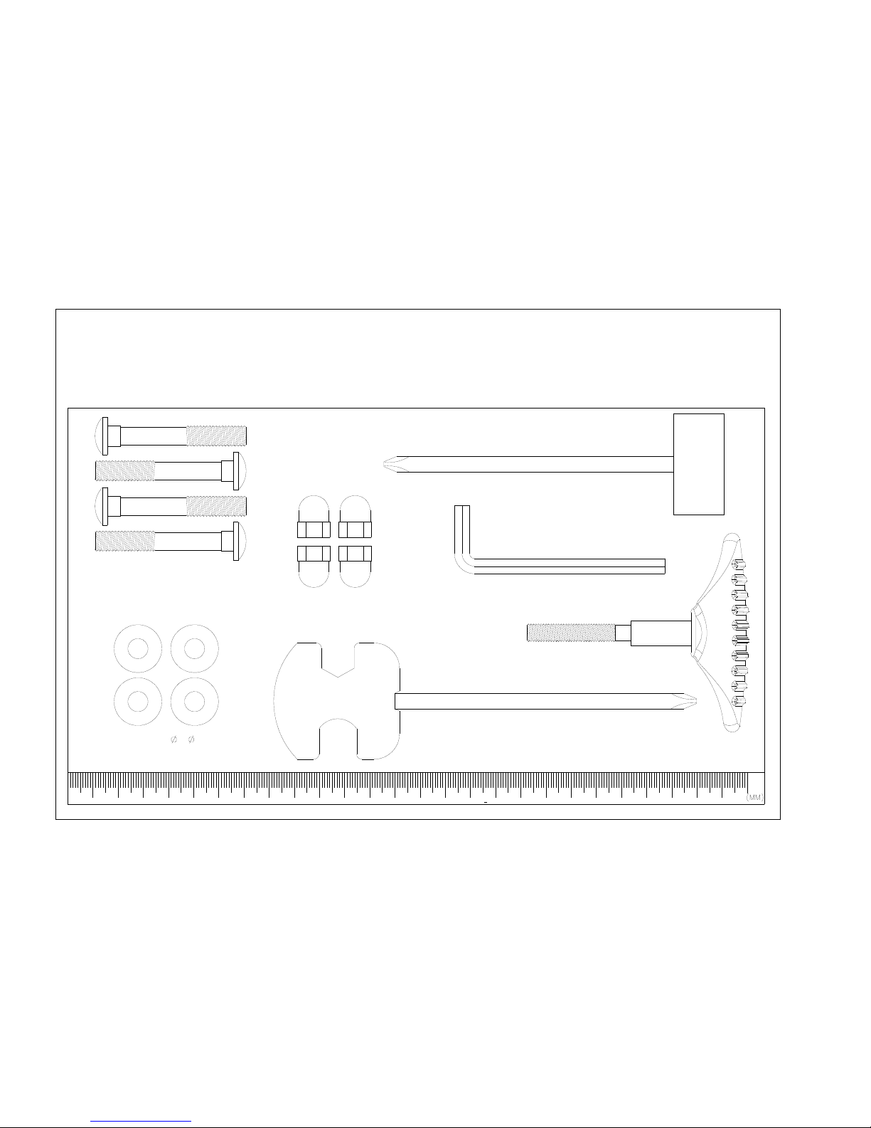
I-6 Screwdriver(1)
91104
NO.I-1 T-shape knob M8*65L(1)
I-8 Box Spanner(1)
I-7 Allen Key(1)
I-5 Acorn Nut for M8 Bolt (4)
I-3 Carriage Bolt M8*55MM (4)
I-4 Curved Washer 8* 19*2t(4)

3
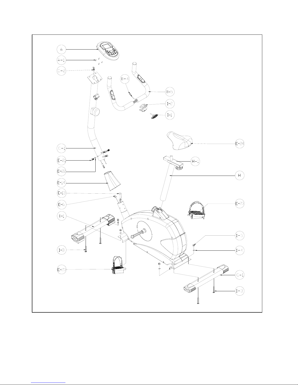
EXPLODE DRAWING
4
COMPLETE BIKE ASSEMBLY

4
PARTS LIST
No. Description Spec. QTY
A,A-1 Computer and screw 1SET
B-1 Cap for handlebar 2PCS
B-2 Hand pulse 2PCS
B-3 Foam grip 2PCS
B-4 Hand pulse wire 1PCS
B-5 Handlebar 1PCS
C-1 Handlebar post 1PCS
C-2 Sensor wire (Upper) 1PCS
C-3 Tension control w/upper cable 1PCS
D-1 Front stabilizer 1PCS
D-2 End cap (Left) 1PCS
D-3 End cap (Right) 1PCS
D-4 Screw 3/16" 2PCS
E-1 Resistant screws M8xP1.0x20L 2PCS
E-2 Adjustable knob 1PCS
E-3 Bearing 2PCS
E-4 Belt 1PCS
E-5 Plastic sleeve 1PCS
E-6 Sensor box 1PCS
E-7 Sensor holder 1PCS
E-8 Screw M4x10L 1PCS
E-9 Chain cover(Left) 1PCS
E-10 Chain cover (Right) 1PCS
E-11 Screw 3/16″6PCS
E-12 Screw M4x50L 6PCS
E-13 Tension control wire (Down) 1PCS
E-14 Cover for handlebar post 1PCS
E-15 C-ring φ17 1PCS
E-16 Flat washer φ17.5xφ25x0.3t 1PCS
E-17 Wave washer φ17.5xφ25x0.3t 1PCS
E-18 Crank (Left) 1PCS
E-19 Crank (Right) 1PCS
E-20 Main frame 1PCS
E-21 Allen bolt M8*P1.25*16L 4PCS
E-22 Semi-circular washer φ8xφ19x2t 4PCS
E-23 Pedal 1PCS
E-24 Seat 1PCS
G-1 Rear stabilizer 1PCS
G-2 End cap for rear stabilizer 2PCS
G-3 Adjustable cap for rear stabilizer 2PCS
H-1 Seat slider 1PCS
H-2 Flat washer φ14.3xφ25x2.0t 1PCS
H-3 Knob for seat slider 1PCS
H-4 Fixing screw bracket 1PCS
H-5 Cap for seat slider 2PCS

5
I-1~I-8 Bolts & nuts pack 1SET
K-1 Hex. Bolt M8xP1.25x12Lx5t 3PCS
K-2 Pulley wheel 1PCS
K-3 Bushing φ22xφ17x7.5mmL 1PCS
K-4 Axle 1PCS
L-1~L-13 Flywheel set 1SET
M Magnetic brake set 1SET
M-1 Hex. Bolt M6xP1.0*16L 2PCS
M-2 Flat washer φ6xφ13x1t 2PCS
M-3 Spring washer φ6 2PCS
N-1~N-10 Idler wheel 1SET

6
ASSEMBLY INSTRUCTION
STEP 1
Using box spanner install the front stabilizer (D-1) with the main frame by using 2 carriage bolts
(I-3), flat washers (I-4) and nuts (I-5). Make sure the transportation wheels are in correct
direction.
Install the rear stabilizer (G-1) with the main frame by using 2 carriage bolts (I-3), flat washers
(I-4) and nuts (I-5).
Assemble the R/L pedal (E-23) onto the crank arm (E-18) by using screwdriver.
I-3 Carriage Bolt M8*55MM (4)
I-4 Curved Washer 8* 19*2t(4)
I-5 Acorn Nut for M8 Bolt (4)
Box Spanner
R
L

7
STEP 2
Assemble the seat (E-24) to the slider (H-1). The slider can be adjusted in different angles.
Tighten the two Nuts under the Seat using a screwdriver. In addition, the Slider can be adjusted
in horizontal level by loosening the Knob.
Insert the seat post (H) into the main frame, then choose the desired position and tighten the
knob. Be sure the adjustable knob (E-2) is always securely fastened
Remarks: When you have chosen a desired position, tighten the seat post knob until you hear a
“click”.
Screwdriver
Box Spanner
8
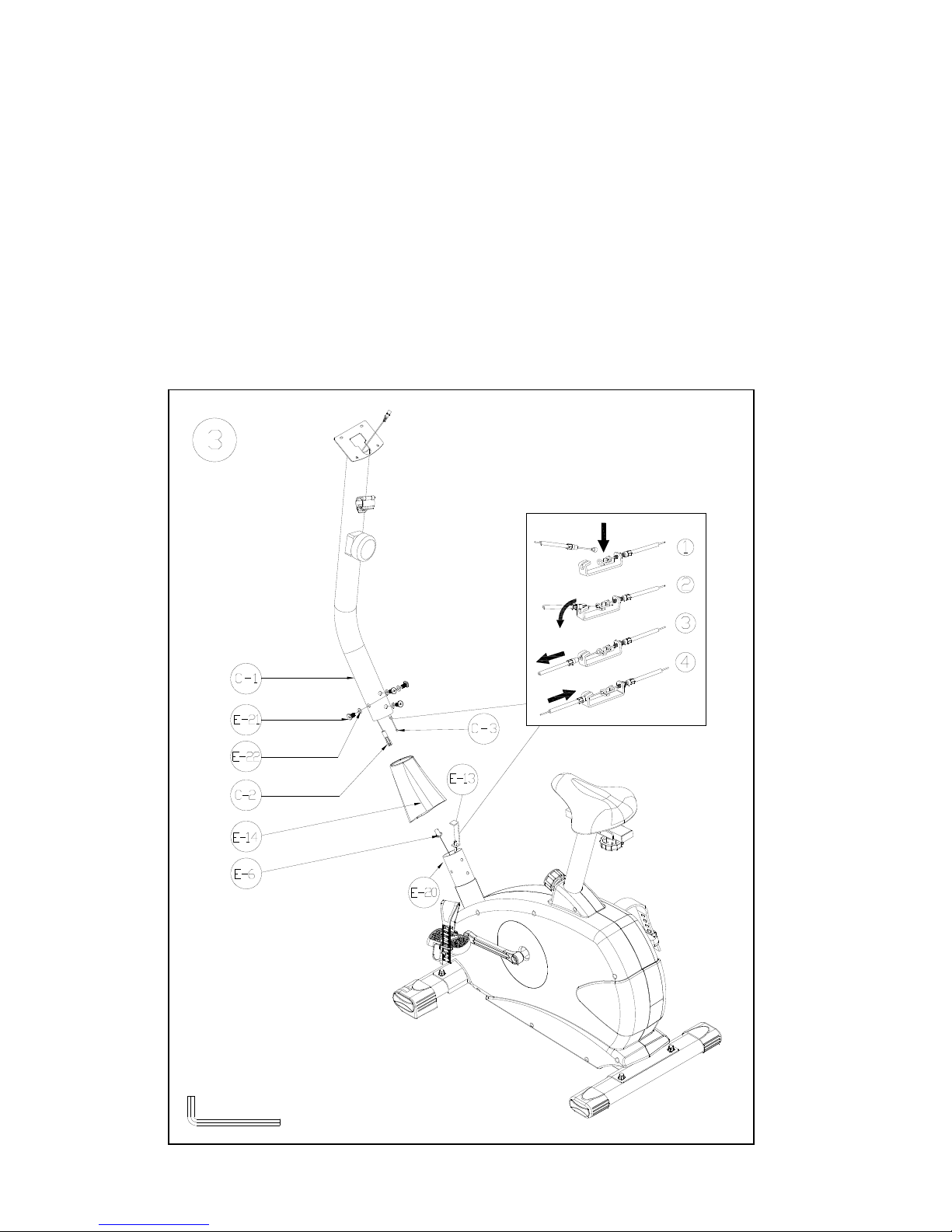
STEP 3
Please remove the allen bolt (E-21) and semi-circular washers (E-22) from the main frame (E-20)
Take the handlebar post cover (E-14) and pass it through handlebar post (C-1).
Connect the Upper sensor wire (C-2) and Down sensor wire (E-6).
Connect the upper tension control wire (C-3) and down tension control wire (E-13).
Insert the handlebar post (C-1) to the main frame with semi-circular washers (E-22) and
allen bolt (E-21) with allen key (I-7).
Remarks: Do not screw of the allen bolt and semicircle washers too firm at one time. It is better
to fix the four sets firmly at the same time because it helps you to change angles and to fix more
easily.
I-7 Allen Key(1)

9
STEP 4
Assembly the handlebar (B-5) onto the handlebar post (C-1).
Place the plastic cover (I-2) on the handlebar (B-5). Insert the T- knob (I-1) into the metal cover.
Make sure it is tightened very well.
Pass the hand-pulse wire (B-4) through the handlebar post hole.
NO.I-1 T-shape knob M8*65L(1)
NO. I-2 Plastic cover

10
STEP 5
Attach the computer (A) to the computer bracket with the enclosed screws (A-1), then connect
the upper sensor wire (B-4) as well as the Hand pulse wire (C-2).

11
INSTRUCTIONAL MANUAL FOR BENEFIT
ST3604 CONSOLE
DISPLAY FUNCTION :
ITEM DESCRIPTION
SCAN
. The sequence of display: TMR→SPD→DST→CAL→PULSE
. In SCAN mode, press MODE key to choose other functions.
. Automatically scan through each mode in sequence every 6 seconds.
SPEED (SPD)
. W/O any signal been transmitted into the monitor for 4 seconds, SPEED
will display “0.0”
. Display current training speed.
TIME (TMR)
. W/O setting the target value, time will count up.
. With setting the target value, time will count down from your target time to
0, and as 0 is achieved time alarm.
. W/O any signal been transmitted into the monitor for 4 seconds, time will
STOP
. Range 0:00 ~ 99:59
DISTANCE (DST)
. W/O setting the target value, distance will count up.
. With setting the target value, distance will count down from your target
distance to 0, and as 0 is achieved distance alarm.
. Range 0.0~999.9 KM
CALORIES (CAL)
. W/O setting the target value, calorie will count up.
. With setting the target value, calories will count down from your target
calorie to 0, and as 0 is achieved calorie alarm.
. Range 0.0~999.9 Cals
.Calorie count on the display only serves as a general guideline. For detail
calorie consumption for each individual please consult a physician or a
nutritionist.
PULSE
. With pulse signal into for 6 seconds, the current pulse will display.
. W/O pulse signal into for 6 seconds, it displays “P”
. Pulse alarm when over preset target pulse.
. Range 0-40~240 BPM

12
BUTTON FUNCTION:
Power on & off:
Power on:
. LCD will display all segments with Bi sound as Drawing A.
Drawing A
Power off:
. Without any signal been transmitted into the monitor for 4 minutes, and the monitor enter to SLEEP.
OPERATION :
1. When monitor power on (or press MODE, RESET key and hold for 3 seconds), LCD will display all segments with
Bi sound for one second and enter to SCAN mode as Drawing B.
2. With any signal been transmitted into the monitor, the value of TMR, DST, and CAL will start to count up as
Drawing C.
3. Without any signal been transmitted into the monitor for 4 minutes, the monitor will enter to SLEEP mode.
DrawingB DrawingC
ITEM DESCRIPTION
Reset
. In setting condition, press RESET key once to reset the current function figures.
. Press RESET key and hold for 2 seconds to reset all function figures, and have Bi sound for
prompt at the same time.
SET
. Each adding by pressing once, press and hold the button to increase the value faster
. TMR setting range: 0:00~99:00 (Each increment is 1:00)
. CAL setting range: 0.0~999.0 (Each increment is 1.0)
. DST setting range: 0.0~999.0 (Each increment is 1.0) KM
MODE
. Choose each function by pressing MODE key. In SCAN mode, press MODE key can lock the
current function.
. Press MODE key and hold for 2 seconds to reset all function figures.

13
Trouble shooting:
. When the display of LCD is weak, it means the batteries need to be changed.
. If there is no signal when you pedal, please check if the cable is well connected.
NOTE :
1. Stop training for 4 minutes, the main screen will be off.
2. If the computer displays abnormally, please re-install the battery and try again.
3. Battery Spec: 1.5V UM-3 or AA (2PCS).
Table of contents
Other Benefit Exercise Bike manuals


