beneq TFS 200 Technical manual

OPERATION INSTRUCTION
TFS 200
N815881
Rev. E
Created:
Toni Parvela, 2010-06-16 16:59:32
Page: 1 (33)
Updated:
ZZ, 2010-06-28 10:05:46
© Beneq 2020
OPERATION INSTRUCTION
TFS 200

OPERATION INSTRUCTION
TFS 200
N815881
Rev. E
Created:
Toni Parvela, 2010-06-16 16:59:32
Page: 2 (33)
Updated:
ZZ, 2010-06-28 10:05:46
© Beneq 2020
Table of contents
1Operating instructions ......................................................................... 4
1.1 General notes .................................................................................... 4
1.1.1 Scope of this manual............................................................. 4
1.2 Startup and shut down procedures/Emergency stop ................................. 4
1.2.1 Cold startup / Recovery from emergency stop ........................... 4
1.2.2 Shut down for a longer period of time ...................................... 5
1.3 Brief operator instructions (manual operations, HMI)................................ 5
1.4 Precursor delivery............................................................................... 7
1.5 Source loading and unloading procedures ............................................... 8
1.5.1 Liquid source ....................................................................... 8
1.5.2 Hot source, HS 500 ............................................................. 12
1.5.3 Hot source, HS 300 ............................................................. 13
1.6 Source adjustments .......................................................................... 16
1.6.1 The gas lines...................................................................... 17
1.6.2 The Ozone source ............................................................... 18
1.6.3 The liquid sources ............................................................... 19
1.6.4 The hot sources.................................................................. 20
1.7 Description of the flow system ............................................................ 21
1.7.1 The process gas flows.......................................................... 21
1.7.2 Gas flows for the instrumentation.......................................... 23
1.7.3 The vacuum system ............................................................ 23
1.8 Flow chart symbols ........................................................................... 23
1.8.1 Key components names ....................................................... 23
1.8.2 Diaphragm valves (DV)........................................................ 24
1.8.3 Solenoid valves (SV) ........................................................... 25
1.8.4 Axial valves (AV) ................................................................ 25
1.8.5 Needle valves (NV) ............................................................. 26
1.8.6 Hand valves (HV)................................................................ 26
1.8.7 Check valves (CV)............................................................... 26
1.8.8 Gate valves (GV) ................................................................ 26
1.8.9 Relief valves (RV) ............................................................... 26
1.8.10 Mass flow controllers (MFC) .................................................. 27
1.8.11 Flow indicators (FT)............................................................. 27

OPERATION INSTRUCTION
TFS 200
N815881
Rev. E
Created:
Toni Parvela, 2010-06-16 16:59:32
Page: 3 (33)
Updated:
ZZ, 2010-06-28 10:05:46
© Beneq 2020
1.8.12 Orifices and Capillaries (CA) ................................................. 27
1.8.13 Temperature sensors (TE) .................................................... 27
1.8.14 Heaters (H) ....................................................................... 28
1.8.15 Pressure transducers and indicators (PT,PIA)........................... 28
1.8.16 Filters ............................................................................... 29
1.9 Factory settings for flow components ................................................... 29
1.9.1 Orifices ............................................................................. 29
1.9.2 Needle valves..................................................................... 29
1.9.3 Gas inlet adjustments.......................................................... 30
1.10 Basic of process tuning ...................................................................... 30
1.10.1 Process tests...................................................................... 30
1.10.2 Underdosing test ................................................................ 31
1.10.3 Process time optimization: ................................................... 32
1.11 Heating and cooling system................................................................ 32
1.12 Residual risks................................................................................... 33
OPERATION INSTRUCTION
TFS 200
N815881
Rev. E
Created:
Toni Parvela, 2010-06-16 16:59:32
Page: 4 (33)
Updated:
ZZ, 2010-06-28 10:05:46
© Beneq 2020
1Operating instructions
1.1 General notes
1.1.1 Scope of this manual
The TFS 200 is designed to be a flexible ALD tool for research. It gives high freedom
for the process engineer to adapt it to daily needs. The flow system is easy to change
and it is possible to run many different types of recipes with TFS 200 system. The
high freedom of using and modifying the TFS 200 system makes it possible to run
this reactor even in undesirable mode. Thus, when changing the precursor tubing
and recipe, the process engineer has to fully understand the operation of the system.
This manual is built to be a handy set of information for the advanced user for getting
a good understanding of the reactor operation and for getting the most out of TFS
200 features. Simple daily operations are described in the chapter "Brief operator
instructions” of this manual.
1.2 Startup and shut down procedures/Emergency stop
1.2.1 Cold startup / Recovery from emergency stop
The cold startup procedure is the following:
-Check the overall condition of the system.
-Open any shutoff hand valves in the carrier gas, instrument gas, and process gas
inlets if closed.
-Turn on the tool main switch located in the electric cabinet.
-Wait approximately 1-2 min, PLC starts.
-Start TFS 200 HMI on the computer, log in to TFS 200 HMI using the valid username
and password.
-Acknowledge pop-up windows related to cold start. E-stop must be acknowledged
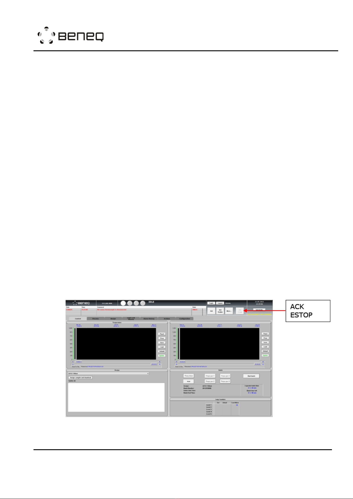
by pressing Ack Estop button from HMI top header.
Figure: Control page of TFS 200 HMI

OPERATION INSTRUCTION
TFS 200
N815881
Rev. E
Created:
Toni Parvela, 2010-06-16 16:59:32
Page: 5 (33)
Updated:
ZZ, 2010-06-28 10:05:46
© Beneq 2020
-Open cooling water shutoff Hand valves if closed.
-When the emergency routine is performed and acknowledged, the system runs the
startup routine automatically. The system runs the startup routine also when
powered up.
-The system is on idle state and ready to run. Alarms can be cleared from the alarm
window.
1.2.2 Shut down for a longer period of time
ALL PRECURSOR HAND VALVES SHOULD BE CLOSED AND CONTAINERS
SHOULD BE REMOVED! RISK OF PRECURSOR LEAKAGE!
Shut down for a longer period of time can be done when the tool is left unattended
for weeks.
Shut down procedure for a longer period of time, when the reactor is left in
atmospheric pressure.
-Pump down the reactor using the pump down button in the control window.
-Remove all precursor containers based on the unloading procedure.
-Vent the reactor using the vent button in the control window.
-Close user interface quit any other programs and shut down the computer.
-If the system is equipped with other than a rotary vane vacuum pump, shut down
the pump according to the pump user manual.
-Turn the power off from the main switch (all valves are closed, vacuum pump stops).
-Turn water and gas inlets off.
Shut down procedure for a longer period of time, when the reactor is left
under the vacuum.
-Pump down the reactor using the pump down button in the control window.
-Remove all precursor containers based on the unloading procedure.
-Set all MFC flows to 0 sccm.
-Close nitrogen main valve and vacuum valves. Keep the reactor under vacuum
condition.
-Close user interface quit any other programs and shut down the computer.
-If the system is equipped with other than a rotary vane vacuum pump, shut down
the pump according to the pump user manual.
-Turn the power off from the main switch (all valves are closed, vacuum pump stops).
-Turn water and gas inlets off.
1.3 Brief operator instructions (manual operations, HMI)
REACTION CHAMBER AND VACUUM CHAMBER PARTS MIGHT BE HOT WHEN
UNLOADING SUBSTRATES WITH TOP-LOADED REACTION CHAMBER! RISK
OF BURN INJURIES!
DO NOT TOUCH ANY PARTS OF THE MACHINE THAT ARE >60 °C! RISK
OF BURN INJURIES!

OPERATION INSTRUCTION
TFS 200
N815881
Rev. E
Created:
Toni Parvela, 2010-06-16 16:59:32
Page: 6 (33)
Updated:
ZZ, 2010-06-28 10:05:46
© Beneq 2020
For daily operation use the following procedures:
Preparation:
-Check the overall condition of the system.
-Check that the precursors are in the right positions.
Pumping down with top-loaded reaction chamber:
-Close the reaction chamber lid.
-Close the vacuum chamber lid.
-Run the pump down routine (by pressing the "Pump down" button in the control
window).
-Check that the machine status is in the IDLE state after the pump down routine
completed.
Pumping down with load lock:
With the load lock chamber installed, you can pump down either the load lock chamber
(in normal operation) or the vacuum chamber (after maintenance) when the gate
valve between the two chambers is closed. If the gate valve is open, both chambers
will be in the same pressure; pumping down or venting one chamber affects the other
chamber too. To pump down the vacuum chamber, follow the instructions of “Pumping
down with top-loaded reaction chamber”.
To pump down the load lock chamber:
-Close the load lock chamber lid.
-Make sure the substrate loader is pulled all the way back to home position.
-Make sure the gate valve is closed.
-Run the load lock pump down routine in the load lock window.
-Check that the machine status is in the IDLE state after the pump down routine
completed.
HANDLE THE VACUUM AND LOAD LOCK CHAMBER LIDS WITH CARE WHEN
OPENING AND CLOSING! RISK OF FINGER INJURY!
Loading/unloading the substrate (with the top-loaded reaction chamber):
-Run the vent routine if the reactor is under vacuum (by pressing the "Vent" button in
the control window).
-Open the vacuum chamber lid.
-Open the reaction chamber lid.
-Unload and/or load the substrate in the reaction chamber.
-Close the reaction chamber lid.
-Close the vacuum chamber lid (and HS 500 hot source lid if present).
-Run the pump down routine (by pressing the "Pump down" button in the control
window).
Loading the substrate through the load lock:
-Make sure that the vacuum chamber is in vacuum.
-The substrate carrier must be in the home position.

OPERATION INSTRUCTION
TFS 200
N815881
Rev. E
Created:
Toni Parvela, 2010-06-16 16:59:32
Page: 7 (33)
Updated:
ZZ, 2010-06-28 10:05:46
© Beneq 2020
-Vent the load lock from the load lock window.
-Open the load lock chamber lid.
-Load the substrate on the substrate carrier.
-Close the load lock chamber lid.
-Pump down the load lock chamber from the load lock window.
-Open the gate valve from the load lock window.
-Push the substrate carrier into the reaction chamber until it is in the front position.
-Lift substrate up by pressing the substrate lifter button. The button is lit when active.
-Pull back substrate carrier to home position.
-Lower substrate by pressing the substrate lifter button. The indication light of the
button goes off.
-Close the reaction chamber for the process by pressing the substrate holder button.
The button is lit when active.
-Close gate valve from the load lock window.
Unloading the substrate through the load lock
-Open the reaction chamber after the process by pressing the substrate holder button.
The indication light of the button goes off.
-Check the loadlock is in vacuum condition.
-Open gate valve from the load lock window.
-Lift substrate up by pressing the substrate lifter button. The button is lit when active.
-Push the substrate carrier into the reaction chamber until it is in front position
-Lower substrate to the carrier by pressing the substrate lifter button. The indication
light of the button goes off.
-Pull back substrate carrier to home position.
-Close gate valve from the load lock window.
-Vent the load lock from the load lock window.
-Open the load lock chamber lid.
-Unload the substrate.
Processing/Run recipe:
-Select and load the right recipe.
-Start the run (by pressing the "Start batch" button in the control window).
-Check that the temperature set values are right.
-Check that the pressure values are at the right level. To avoid precursor leaking from
the reaction chamber to the vacuum chamber, the pressure of vacuum chamber should
always be higher than the reaction chamber.
-Follow the instructions given by pop-up windows which are defined in the recipe, i.e.
the substrate and precursor temperatures reach to setting points, hand valves of
precursor containers are opened and etc.
1.4 Precursor delivery
RISK OF INJURY DUE TO HIGH PRESSURE FLUIDS AND GASES IN THE
PRECURSOR LINES! SAFETY GOGGLES IS RECOMMENED DURING THE
OPERATION.
In general, the precursor delivery can be described in several different ways, while the
three most common ways are the following:

OPERATION INSTRUCTION
TFS 200
N815881
Rev. E
Created:
Toni Parvela, 2010-06-16 16:59:32
Page: 8 (33)
Updated:
ZZ, 2010-06-28 10:05:46
© Beneq 2020
•Own vapor pressure
The precursor material is actually boiling when the pressure in the container is
dropping during the pulse. This method is most common for materials with the
vapor pressure of at least 10 mbar at source temperature.
•Carrier gas assisted delivery
The carrier gas and pulse valves are opened simultaneously. The carrier gas
flows through the precursor container making the flow of lower vapor pressure
precursor more efficient.
•Carrier gas assisted booster delivery
The carrier gas is first loaded into the container to increase the pressure inside
the container. Then the pulse valve is opened to release the mixture of carrier
gas and precursor vapor from the container. This is the most efficient way of
delivering a low vapor pressure material from the container. This method should
not be used for high vapor pressure materials since there is a risk of precursor
flowing to the carrier gas feeding line.
1.5 Source loading and unloading procedures
PRECURSOR RESIDUALS MIGHT BE STILL PRESENT IN THE LINES! EXTRA
PRECAUTIONS SHOULD BE TAKEN WHEN OPENING ANY CHEMISTRY
LINES OF THE SYSTEM! PROPER PURGING OF THE LINES IS NEEDED!
RISK OF PRECURSOR LEAK DUE TO WRONG ASSEMBLY OF PRECURSOR
CONTAINERS OR DURING INSTALLATION CONTAINER MIGHT FALL OVER
CAUSING LEAK TO THE ATMOSPHERE!
1.5.1 Liquid source
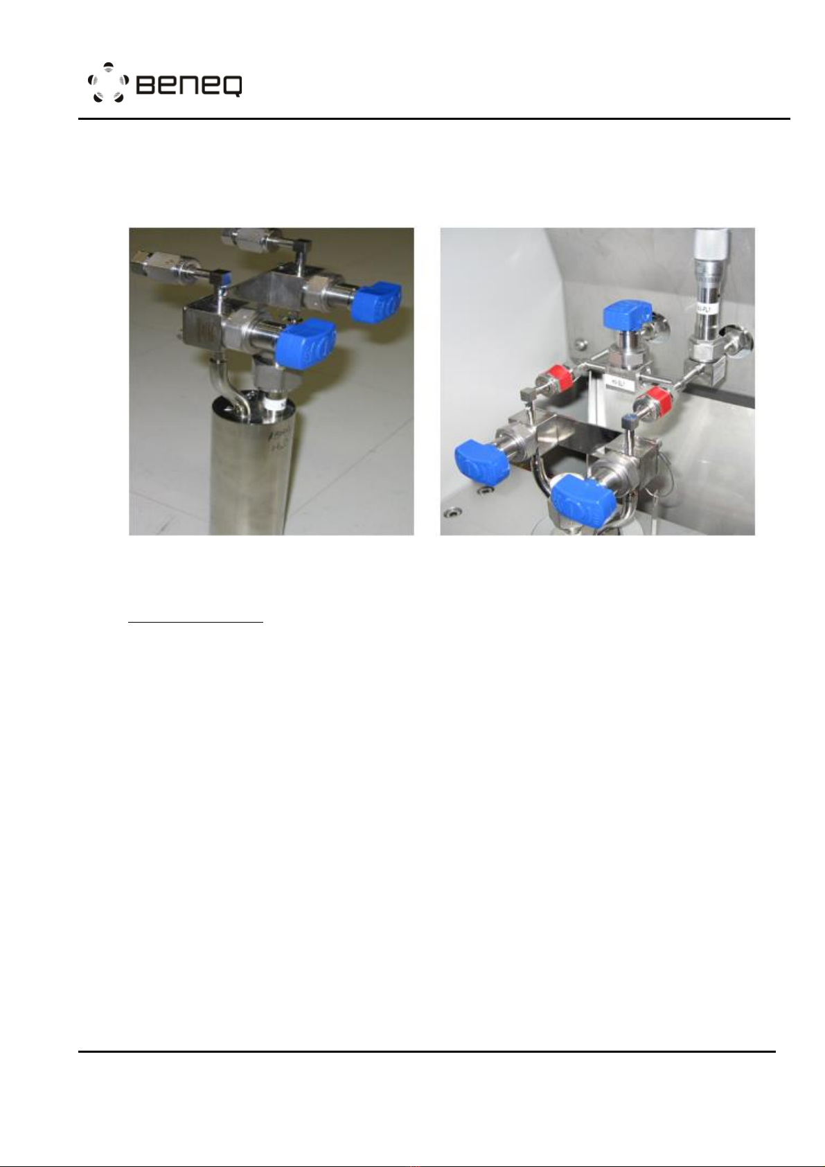
Liquid precursor materials are packed into metal containers. Liquid precursor
containers can be called “Liquid container with a single line”and “Liquid container
with dual lines”. “Liquid container with a single line”has only one connection with ¼"
VCR type metal fitting while the “Liquid container with dual lines” has two connections
with ¼" VCR type metal fittings. For all liquid containers, the material filling is a ½”
VCR fitting and the recommended maximum filling is 50% of the container capacity.
Liquid container with a single line
One hand valve is connected to the precursor outlet of the container.
PRECURSOR MATERIALS CAN BE DANGEROUS. PLEASE FOLLOW THE
CHEMICAL RELATED MSDS (MATERIAL SAFEY DATA SHEET).
HANDLE THE CONTAINERS WITH CARE DURING THE LOADING AND
UNLOADING PROCEDURES. ENSURE THE CONTAINER HAND VALVES ARE
CLOSED!

OPERATION INSTRUCTION
TFS 200
N815881
Rev. E
Created:
Toni Parvela, 2010-06-16 16:59:32
Page: 9 (33)
Updated:
ZZ, 2010-06-28 10:05:46
© Beneq 2020
Figure: Liquid container with a single line
Container loading
-Make sure that the container hand valve is closed.
-Remove the blind VCR caps from the container connectors and the TFS 200 feeding
line. (It is recommended to have caps plugged on the TFS 200 feeding lines when
source container is not in place.)
-Remove the used VCR gaskets.
-Place new VCR gaskets.
-Put the filled liquid source container to the right position in the aluminum support.
-Tighten the VCR fittings.
-Pump down the reactor into vacuum if not done already.
-Check that the machine is in an IDLE state.
-Leakage test VCR connections.
-Make sure the reaction chamber sealed well (there is the pressure difference
between reaction and vacuum chambers).
-Run container loading routine from either “control page” or “precursor page”of TFS
200 HMI based on the position of the liquid container.
NOTE: if the container is already under the vacuum, it is not necessary to
have Micropulsing in routine.

OPERATION INSTRUCTION
TFS 200
N815881
Rev. E
Created:
Toni Parvela, 2010-06-16 16:59:32
Page: 10 (33)
Updated:
ZZ, 2010-06-28 10:05:46
© Beneq 2020
Figure: Control page of TFS 200 HMI
Figure: Precursor page of TFS 200 HMI
Container unloading
-Make sure that the container hand valve is closed.
-Pump down the reactor to vacuum if not done beforehand.
-Make sure the reaction chamber sealed well (there is the pressure difference
between reaction and vacuum chambers).
-Run container unloading routine from either “control page” or “precursor page”of
TFS 200 HMI based on the position of the liquid container.
-Open the VCR fitting between machine and container.
-Remove the container.
-Plug the open fittings on both machine and container with blind VCR caps.
OPERATION INSTRUCTION
TFS 200
N815881
Rev. E
Created:
Toni Parvela, 2010-06-16 16:59:32
Page: 11 (33)
Updated:
ZZ, 2010-06-28 10:05:46
© Beneq 2020
Liquid container with dual lines
Two hand valves are connected to the container, one to gas inlet and one to precursor
outlet. Hand valves are connected to each other by a purge flow valve HV-SLx which
is used only when the container is removed/installed.
Figure: Liquid source precursor container (Left) and the connections to TFS 200
(Right). Red marks show the fittings that are opened and fastened when the
container is removed and installed. The purge valve is in the middle.
Container loading
-Make sure that container hand valves are closed.
-Make sure that purge valve HV-SLx is in purge position (valve handle is in position
open).
-Remove the blind VCR caps from the container connectors and the TFS 200 feeding
line. (It is recommended to have caps plugged on the TFS 200 feeding lines when
source container is not in place.)
-Remove the used VCR gaskets.
-Place new VCR gaskets.
-Put the filled liquid source container to the right position in the aluminum support.
-Tighten the VCR fittings.
-Pump down the reactor into vacuum if not done already.
-Fully open the needle valve (NV-PLx, where x is the liquid source number).
-Check that the machine is in an IDLE state.
-Leakage test VCR connections.
-Make sure the reaction chamber sealed well (there is the pressure difference
between reaction and vacuum chambers).
-Run container loading routine from either “control page” or “precursor page”of TFS
200 HMI based on the position of the liquid container.
-Close the purge valve HV-SLx.
-Adjust back the needle valve setting.
OPERATION INSTRUCTION
TFS 200
N815881
Rev. E
Created:
Toni Parvela, 2010-06-16 16:59:32
Page: 12 (33)
Updated:
ZZ, 2010-06-28 10:05:46
© Beneq 2020
NOTE: if the container is already under the vacuum, it is not necessary to
have Micropulsing in routine.
Container unloading
-Make sure that the container hand valve is closed.
-Pump down the reactor to vacuum if not done beforehand.
-Fully Open the needle valve (NV-PLx).
-Turn purge valve HV-SLx to purge position (valve handle position open).
-Make sure the reaction chamber sealed well (there is the pressure difference
between reaction and vacuum chambers).
-Run container unloading routine from either “control page” or “precursor page”of
TFS 200 HMI based on the position of the liquid container.
-Open the VCR fittings between machine and container.
-Remove the container.
-Plug the open fittings on both machine and container with blind VCR caps.
1.5.2 Hot source, HS 500
HOT SURFACES AT HOT SOURCE PARTS WHEN HEATING THEM UP ABOVE
100°C. RISK OF BURN INJURY!
PRECURSOR MATERIALS CAN BE DANGEROUS. PLEASE FOLLOW THE
CHEMICAL RELATED MSDS (MATERIAL SAFEY DATA SHEET).
HANDLE THE CONTAINERS WITH CARE! DO NOT OVERHEAT PRECURSOR
MATERIALS RISK OF UNCONTROLLED OVERPRESSURE BUILD UP IN THE
CONTAINER!
Semi-inert hot source (solid source) HS 500 has the capability to operate at
temperatures up to 500°C. This is possible because the pulsing is made by inert gas
valving. On the other hand, it is not possible to load/unload this type of hot source
without breaking the vacuum in the reactor.
This source type is designed to be used for very low vapor pressure materials. The
precursor delivery method is always carrier gas assisted pulsing mode.
HS 500 source cartridge loading
-Run vent routine from TFS 200 HMI to increase the pressure in the vacuum chamber
and HS 500 to atmospheric pressure.
-Fill the source cartridge (under glove box if needed).
-Open the source back flange and push the cartridge into the source tube.
-Close the back flange as far it goes without pressing the spring loaded hot source
cartridge.
-Set MFC-NOP and MFC-NOV flow to 1000 sccm for purging the HS 500.
-Wait 1 minute.
-Set MFC-NOP and MFC-NOV flow to 300 sccm.

OPERATION INSTRUCTION
TFS 200
N815881
Rev. E
Created:
Toni Parvela, 2010-06-16 16:59:32
Page: 13 (33)
Updated:
ZZ, 2010-06-28 10:05:46
© Beneq 2020
-Push the back flange completely closed and lock it by pressing the handle gently.
-Pump down the reactor to vacuum
HS 500 source cartridge unloading
-Ensure that HS 500 is cooled down
-Run the vent routine from TFS 200 HMI to increase the pressure in the vacuum
chamber and HS 500 to atmospheric pressure.
-Open the source back flange and pull out the used cartridge.
1.5.3 Hot source, HS 300
HOT SURFACES AT HOT SOURCE PARTS WHEN HEATING THEM UP ABOVE
100°C. RISK OF BURN INJURIES!
PRECURSOR MATERIALS CAN BE DANGEROUS. PLEASE FOLLOW THE
CHEMICAL RELATED MSDS (MATERIAL SAFEY DATA SHEET).
HANDLE THE CONTAINERS WITH CARE! DO NOT OVERHEAT PRECURSOR
MATERIALS RISK OF UNCONTROLLED OVERPRESSURE BUILD UP IN THE
CONTAINER!
The HS 300 can be heated up to 300°C and is designed for liquid and solid precursor
materials that need heating to reach sufficient vapor pressure. Precursor pulsing can
be done using either material's own vapor pressure or different ways of carrier gas
assisted pulsing. These methods are described in more detail in Chapter 1.4.
The recommended maximum filling of the precursor container is 150 ml. After
precursor filling, the container pressure can be different compared to normal process
pressure. As an example: if the precursor filling has been done at atmospheric
pressure and the deposition process will be done at vacuum, the higher pressure
from the container will cause higher flow into the reactor during the first pulses. This
may cause reactor contamination.
To avoid this, please follow the procedure:
HS 300 container loading
-Make sure that container hand valves are closed.
-Remove the blind VCR caps from the container connectors and the TFS 200 feeding
lines. (It is recommended to have caps plugged on the TFS 200 feeding lines when
source container is not in place.)
-Remove the used VCR gaskets.
-Place new VCR gaskets.
-Put the filled HS 300 container to the right position.
-Tighten the VCR fittings.
-Pump down the reactor into vacuum if not done already.
-Check that machine is in IDLE state
-Leakage test VCR connection.
-Make sure the reaction chamber sealed well (there is the pressure difference
between reaction and vacuum chambers).

OPERATION INSTRUCTION
TFS 200
N815881
Rev. E
Created:
Toni Parvela, 2010-06-16 16:59:32
Page: 14 (33)
Updated:
ZZ, 2010-06-28 10:05:46
© Beneq 2020
-Run source loading recipe of the HS 300 container. If it can not be found in the
recipe list, please contact Beneq. An example is shown below,
---------------------------------------------------------------------------------------------
*Recipe Loading Hot source 1 Precursor
*Recipe for purging hot source 1 line after attaching the container to the machine
*Based on flow chart N502400
*Program start
SPROG
*Open the N2 main valve and chamber flow valve and make sure filling valve is closed
OPEN DV-SN1,DV-NV2
CLOSE DV-NV1
*Check the vacuum level
WUNTIL PT-P1<10 10s
*Open main vacuum valve
OPEN DV-VP1
*Set flows
FLOW MFC-NOVS=300
FLOW MFC-NOPS=600
*Close pulse valves
CLOSE DV-PL1,DV-BL1
CLOSE DV-PL2,DV-BL2
CLOSE DV-PL3,DV-BL3
CLOSE DV-PL4,DV-BL4
CLOSE DV-PH1,DV-BH1,DV-BHA1
CLOSE DV-PH2,DV-BH2,DV-BHA2
CLOSE DV-PH3,DV-BH3,DV-BHA3
*Close process gas valves
CLOSE DV-PN1,DV-PN2
CLOSE DV-PG1,DV-PG2
CLOSE DV-PG6,DV-PG7,DV-PG8
CLOSE DV-PG1C,DV-SG02,DV-PG6C,DV-PG7C
*close precursor hand valves
WRITE M7
WUSER YES
*confirm that all precursor hand valves are closed
WRITE M22
WUSER YES
*Purge hot source 1 line
OPEN DV-PH1,DV-BH1
WTIME 1min
REPEAT 8
PULSE DV-BHA1 10s
WTIME 2min
REND
CLOSE DV-PH1,DV-BH1
*Prepare for processing
WRITE M6
WUSER YES
*mircopulsing to evacuate canister
REPEAT 80
PULSE DV-PH1 50ms
WTIME 1s
REND
REPEAT 100
PULSE DV-PH1 100ms
WTIME 1s
REND
*close precursor hand valves
WRITE M7
OPERATION INSTRUCTION
TFS 200
N815881
Rev. E
Created:
Toni Parvela, 2010-06-16 16:59:32
Page: 15 (33)
Updated:
ZZ, 2010-06-28 10:05:46
© Beneq 2020
WUSER YES
*Purge hot source 1 line again
OPEN DV-PH1,DV-BH1
WTIME 1min
CLOSE DV-PH1,DV-BH1
*end program
EPROG
---------------------------------------------------------------------------------------------
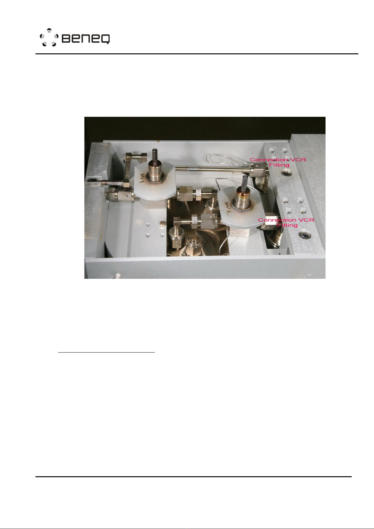
Figure: HS 300 container with the feeling lines. Red marks show the fittings that
are opened and fastened when the container is removed and installed.
NOTE: Preferably use metal (copper) seals in the top flange. If using
polymer seals, make sure seal material is compatible with the chemical and
the temperature used. A new container is always filled with Air. Please open
the container before transferring it into the glove box for chemical filling.
HS 300 container unloading
-Ensure that HS 300 is cooled down.
-Make sure that the container hand valve is closed.
-Pump down the reactor into vacuum if not done beforehand.
-Make sure the reaction chamber sealed well (there is the pressure difference
between reaction and vacuum chambers).
-Run source unloading recipe of the HS 300 container. If it can not be found in the
recipe list, please contact Beneq. An example is shown below,
---------------------------------------------------------------------------------------------
*Recipe Unloading Hot source 1 Precursor
*Recipe for purging hot source 1 line after detaching container from the machine
*Based on flow chart N502400
*Program start
SPROG
*Open the N2 main valve and chamber flow valve and make sure filling valve is closed
OPEN DV-SN1,DV-NV2

OPERATION INSTRUCTION
TFS 200
N815881
Rev. E
Created:
Toni Parvela, 2010-06-16 16:59:32
Page: 16 (33)
Updated:
ZZ, 2010-06-28 10:05:46
© Beneq 2020
CLOSE DV-NV1
*Check the vacuum level
WUNTIL PT-P1<10 10s
*Open main vacuum valve
OPEN DV-VP1
*Set flows
FLOW MFC-NOVS=300
FLOW MFC-NOPS=600
*Close pulse valves
CLOSE DV-PL1,DV-BL1
CLOSE DV-PL2,DV-BL2
CLOSE DV-PL3,DV-BL3
CLOSE DV-PL4,DV-BL4
CLOSE DV-PH1,DV-BH1,DV-BHA1
CLOSE DV-PH2,DV-BH2,DV-BHA2
CLOSE DV-PH3,DV-BH3,DV-BHA3
*Close process gas valves
CLOSE DV-PN1,DV-PN2
CLOSE DV-PG1,DV-PG2
CLOSE DV-PG6,DV-PG7,DV-PG8
CLOSE DV-PG1C,DV-SG02,DV-PG6C,DV-PG7C
*close precursor hand valves
WRITE M7
WUSER YES
*confirm that all precursor hand valves are closed
WRITE M22
WUSER YES
*Purge hot source 1 line
OPEN DV-PH1,DV-BH1
WTIME 1min
REPEAT 8
PULSE DV-BHA1 10s
WTIME 2min
REND
CLOSE DV-PH1,DV-BH1
*end program
EPROG
---------------------------------------------------------------------------------------------
-Open the two VCR fittings between machine and container.
-Remove the container.
-Plug the open fittings on both machine and container with blind VCR caps.
NOTE: Always make sure you are not overheating the precursor in the
container. Some precursors may contain for example water or other volatile
components that may be released during heating. This kind of precursors
may generate overpressure in the container when it is heated. Use pure
chemicals and monitor the pressure build-up during the first heating. The
risk of uncontrolled pressure builds up in the container! Risk of damaging
the source and uncontrolled precursor release!
1.6 Source adjustments
The TFS 200 ALD system has three main types of sources; gas, liquid (cold) and hot
sources. For hot sources, there are two different source constructions, HS 300 and HS
500.
OPERATION INSTRUCTION
TFS 200
N815881
Rev. E
Created:
Toni Parvela, 2010-06-16 16:59:32
Page: 17 (33)
Updated:
ZZ, 2010-06-28 10:05:46
© Beneq 2020
1.6.1 The gas lines
RISK OF TOXIC AND FLAMMABLE GAS LEAK TO THE ROOM ATHMOSPERE!
EXTRA PRECONSCIOUS STEPS SHOULD BE TAKEN ACCORDING TO MSDS,
LOCAL LAW, HEALTH AND SAFETY REGULATIONS!
RISK OF NON-COMPATIBLE REACTIVE GASES TO BE SWITCHED ON
SIMULTANEOUSLY DURING PROCESS!
The TFS 200 is equipt with gas lines for both thermal and plasma ALD operation as
shown in the figure below. For thermal ALD operation, the gas lines are not equipped
with mass flow controllers (MFC) for each gas line and usually the MFC controlled gas
lines are used for plasma gases that are not pulsed during the deposition. Plasma
gas lines are equipped with a pressure switch which prevents the pulsing valves to
be operated in case that the plasma gas feeding line is not under vacuum.
The precursors from the gas sources are delivered to the reactor by all-welded ¼"
SS tubes. The VCR type connection point is inside the machine frame.There is a
pulsing valve in the gas line, which leads the gas into the feeding line. The gas flow
is restricted with a flow orifice, which is located in the inlet connector of the pulsing
valve. The feeding lines of gas lines can be grouped in different ways. Plasma gases
are mixed to a common feeding line which goes to the plasma electrode through the
top lid of the vacuum chamber. Gas lines for thermal ALD are grouped into up to 3
separate feeding lines, which all have separate inlet connectors at the bottom of the
vacuum chamber.
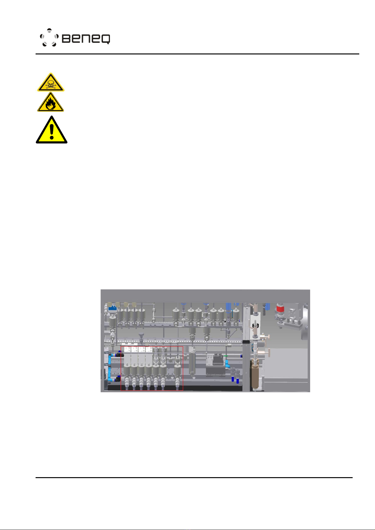
Figure: The area marked with red, starting from the left side it shows four Plasma
lines equipped with MFCs, two flammable/toxic gas lines and a normal gas line.
Both thermal and plasma gas lines can be further separated into two types: a) Normal
gas line and b) Flammable/toxic gas line. The normal gas line is usually used for
gasses such as N2, O2, H2and the flammable/toxic line is used for gasses such as
NH3, H2S, WF6and more. For both types, software interlocks are used in cases of non-
combatible gasses which doesn’t allow the operation of the pulsing valves at the
same time. Both types of gas lines include line filters, inlet check valves for

OPERATION INSTRUCTION
TFS 200
N815881
Rev. E
Created:
Toni Parvela, 2010-06-16 16:59:32
Page: 18 (33)
Updated:
ZZ, 2010-06-28 10:05:46
© Beneq 2020
preventing flow from the TFS 200 to the facility system in a fault situation, pusling
vavles and orifices for flow adjustment. The flammable/toxic gas line is equipted with
more safety features such as double interlock valves on the gas supply, double
interlock pressure switches on the vacuum chamber for vacuum level monitoring and
interlocked to material feeding valves, check vavles on the purging line for preventing
the gas flowing back to the nitrogen line.
1.6.2 The Ozone source
RISK OF OZONE LEAK TO THE ROOM ATMOSPHERE DUE TO LEAKING
FEEDING TUBES, OZONE DESTRUCTOR DOES NOT WORK PROPERLY!
RISK OF OZONE RESIDUALS PRESENT IN THE VENTILATION LINE! EXTRA
PRECONSCIOUS STEPS SHOULD BE TAKEN ACCORDING TO MSDS, LOCAL
LAW, HEALTH AND SAFETY REGULATIONS!
The ozone source is enclosed within a ventilation cabinet as shown in the figure below.
Oxygen is fed into the ozone generator which generates the ozone to be used for the
ALD process. Due to the short limiting lifetime of ozone, there are both inlet and
outlet connections for the ozone line. This allows ozone to circulate through the
source tubes. During pulsing, the pulse valve will take enough material from the
circulation.
Figure: Ozone source cabinet
An ozone destructor is included in the source tube for destroying the bypass flow of
ozone and sending the residual O2by-product to the facilitie’s ventilation line. In
addition, the ozone cabinet is equipt with an ozone detector which is used to trigger
an alarm in case of ozone leakage caused within the ozone cabinet. A fatal alarm
would be triggered if the level detected by the ozone sensor is above a preset value
which will automatically close all process valves.
After the chemical reactions within the Reaction Chamber, excess gasess flow
through the exhaust line to the pump and then to the facilitie’s ventilation line. There

OPERATION INSTRUCTION
TFS 200
N815881
Rev. E
Created:
Toni Parvela, 2010-06-16 16:59:32
Page: 19 (33)
Updated:
ZZ, 2010-06-28 10:05:46
© Beneq 2020
is a possible risk that ozone residuals may enter the ventilation line and in this case
an ozone destroyer should be installed in the ventilation line of factory to eliminate
this risk.
1.6.3 The liquid sources
RISK OF PRECURSOR LEAK TO THE ATMOSPHERE DUE TO VERY HIGH
PRESSURE OF N2 CARRIER GAS! FEEDING N2 WITH HIGH PRESSURE IN
THE CONTAINER MIGHT CAUSE LEAKING OF THE PRECURSOR!
The liquid sources are designed for precursor materials that have enough vapor
pressure at room temperature for vacuum processing. The source containers are
located in a temperature-stabilized aluminum block. Normally the temperature is
adjusted to about 19-20°C for ensuring that the vapor pressure does not change
according to room temperature changes. Furthermore, the lower source temperature
minimizes the risk of condensation in the tubing between the source material
container and the reactor. The temperature is kept constant either by a separate
chiller (option) or other sources of cold water. The cooling liquid is circulating inside
the aluminum block.
The most common way to use this kind of high vapor pressure source is "pulsing by
own vapor pressure". In this case, the precursor vapor pressure is higher than the
pressure in the reaction chamber feeding tube. By opening the pulsing valve of the
liquid source (DV-PLx, x is the number of sources), the precursor vapor flows into
the reaction chamber. The needle valve (NV-PLx) or orifice is used to adjust the flow
to the right dosage level. The dose is also affected by pulse time and source
temperature.
If the precursor vapor pressure is not significantly greater than the feeding tube
pressure, it is possible to run this source in the "carrier gas assisted delivery" mode.
In this case, both container valves of DV-PLx and DV-BLx are opened simultaneously,
and thus the carrier gas is mixed with the precursor material. The dose is dependent
on the precursor vapor pressure, the total pressure of the container, reaction
chamber feeding tube pressure and the carrier gas flow rate. Precursor vapor
pressure is a physical value depending on source temperature. Flow is adjusted by
the mass flow controller and the overall pressure of the container can be adjusted by
the needle valve. Reaction chamber feeding tube pressure is dependent on all MFC
flow rates. This means that the dosing can be increased by opening the needle valve
or increasing the MFC flow rate. The dose is also affected by pulse time and source
temperature.
If the precursor vapor pressure is significantly lower than system pressure, the
“Carrier gas assisted booster delivery”mode can be used. This delivery type is based
on two steps: a) increasing the container pressure by pulsing nitrogen through the
DV-BLx valve and b) pulsing the mixture of carrier gas and precursor into the
chamber by opening the DV-PLx valve.

OPERATION INSTRUCTION
TFS 200
N815881
Rev. E
Created:
Toni Parvela, 2010-06-16 16:59:32
Page: 20 (33)
Updated:
ZZ, 2010-06-28 10:05:46
© Beneq 2020
1.6.4 The hot sources
RISK OF BURN INJURIES! HOT SOURCES AND SARROUNDING PARTS
MIGHT BE HOT! USE PROTECTIVE HEAT SHIELD WHEN OPERATING!
RISK OF UNCONTROLLED PRECURSOR FLOW DUE TO OVERHEAT OF
PRECURSOR MATERIAL TO THE TEMPERATURES WHERE ITS VAPOR
PRESSURE EXCEEDS REACTOR PRESSURE!
RISK OF PRECURSOR LEAK TO THE ATMOSPHERE DUE TO VERY HIGH
PRESSURE OF N2 CARRIER GAS! FEEDING N2 WITH HIGH PRESSURE IN
THE CONTAINER MIGHT CAUSE LEAKING OF THE PRECURSOR!
There are two types of hot sources: HS 300 and HS 500.
Hot source HS 500
This hot source type utilizes the most commonly used and robust technology for
reaching high source temperature. This is mainly needed for materials with low vapor
pressure (most of them are solid). The flow system is always the "purge assisted"
type. The inert carrier gas flows are used to prevent leakage from hot source volume
to the reaction chamber volume (and vice versa) between pulses. The dosing can be
adjusted by changing precursor vapor pressure (Source temperature change), by
changing the carrier gas flow rate and by changing the pulse time.
Hot source HS 300
When the precursor material needs moderate heating, it is possible to use this hot
source type. The flow system is very similar to the liquid source and the delivery
methods can be found in Chapter 1.4. The source can be heated up to 300°C. It is
designed for both liquid and solid precursor materials.
When using this source type in "own vapor pressure” mode, the temperature should
be high enough to get precursor vapor pressure above the system pressure. There
are no adjustable needle valves integrated into the hot source. This means that the
pressure should be only slightly above the system pressure for minimizing the
overdose of precursors. The dose can be adjusted by pulse time and source
temperature.
Using “carrier gas assisted booster delivery”mode, the chemical decomposition of
the low vapor pressure precursors can be avoided. This type of delivery mode can be
done by pulsing the carrier gas valve to increase the container pressure and then by
opening the pulsing valve to release the carrier gas and precursor mixture to the
reaction chamber. The dose of the precursor can be adjusted by changing the
precursor temperature or by changing the length of the carrier gas/precursor pulse.
Typically, the carrier gas/precursor pulse ratio is kept constant. The relatively long
time is often needed to generate enough pressure in the container.
Table of contents
Popular Industrial Equipment manuals by other brands

Nordson
Nordson ColorMax Customer product manual

Siemens
Siemens LITHOSTAR Multiline Repair instructions

Jäger
Jäger S62-M360.06 S5 manual

Bühler technologies
Bühler technologies BWT Series Installation and operation instructions

Surewerx
Surewerx VPT Series owner's manual

Siemens
Siemens SIRIUS 8WD4428-0BC operating instructions


