Benewake CE30-A User manual

Page 1
CE30-A Solid State Array LiDAR
Operation Manual
Benewake (Beijing) Co., Ltd.

Page 2
Table of Contents
1CE30 Introduction.................................................................................................................. 3
2Indicator Instruction ............................................................................................................... 4
3Software Operation Instruction............................................................................................... 4
4Description on Line Sequence ................................................................................................ 6
5Installation Instruction............................................................................................................ 6
6Method of Center Calibration ................................................................................................. 7
7Head Dissipation Component and Reference Design............................................................... 8
8Application Case .................................................................................................................... 9
8.1 Accurate Crossing........................................................................................................... 9
8.2 Detection of Low Obstacles............................................................................................. 9
9Influence Factors of Measurement .......................................................................................... 9
9.1 Multi Optical Path........................................................................................................... 9
9.2 Stray Light.................................................................................................................... 10
9.3 Multi Distance Objects.................................................................................................. 11

Page 3
1CE30 Introduction
CE30 is an IR DE-LiDAR developed on the basis of ToF principle. With the optimized obstacle
avoidance mode, the detecting region of interest can be set up. The single-point projection distance of
the nearest obstacle can be transferred through CANBUS. Compared with single-channel scanning
LiDARs, CE30 does not contain any rotating components. The reliability of long-time work and a
wider vertical detection range can be ensured.
Product Properties
Complete solid-state LiDAR
Array detection
Horizontal field of view: > 120°; vertical field of view: 9°
Set region of interest in the obstacle avoidance mode
Calculate the nearest point and output with CANBUS
1. Shell
2. Receiving panel (working area, no coving)
3. Sending panel (working area, no coving)
4. Power supply/CANBUS (M8 aerial socket)
5. Ethernet port (M8 aerial socket)
6. Equipment installing hole (M3)
Fig. 1 Outline of DELIADAR CE30

Page 4
2Indicator Instruction
1. Blue light: ready state, ready for connection and running
2. Blue flash: running state
3. Red flash: missing of relevant running files
4. Red light: fatal error (abnormal signal, abnormal interface communication, abnormal I2C, etc.)
Fig. 2 Indicator Drawing
3Software Operation Instruction
1. Connect all the accessories in accordance with Fig. 3 Illustration for Connection of Components.
Fig. 3 Illustration for Connection of Components
2. Plug into 12V-DC2.5 power. The supply current must be above 2A. Connect the mini USB
interface on the adapter plate with the computer.
3. Wait for about 35s for normal start of the LiDAR. Then the heartbeat packet is transferred with
blue light flashing, indicating the state of waiting orders.
Operate according to Fig. 4 to start the software. Demonstration and data recording can be achieved
with the software.

Page 5
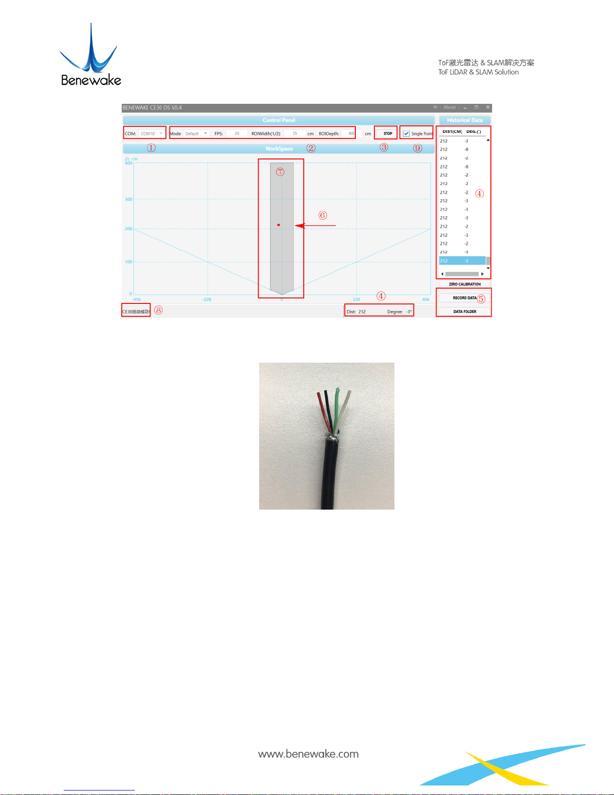
Fig. 4 Illustration of Software Functions
Note
①The software could automatically identify two kinds of UART: one for data and another is for
debugging information. Please choose appropriate UART number in accordance with
computer properties.
②Default setting of obstacle avoidance area is 35 cm in half-width of the ROI and 400 cm in
depth.
③Start/ stop test button
④View data by rolling the window
⑤Button of data recording (In unit of minute. When multiple clicks of the button within one
minutes, only the data of the last click will be recorded.)
⑥Position of the nearest obstacle detected by LiDAR
⑦Obstacle avoidance region: with presence of an object, as shown in Fig. 4 above, the software
will label the area between LiDAR and the obstacle as the safe zone with coloring, or else the
background will be white.
⑧Running state
⑨Single-point mode
If the single-point mode is chosen, as shown in Fig. 5 below, the software will indicate the specific
position of the obstacle in ROI. (Instruction: during the measurement of a wide flat obstacle, the
output angle might be the angle of any point on the object, because the LiDAR only outputs one
point.)

Page 6
Fig. 5 Illustration of Single-point Mode
4Description on Line Sequence
Fig. 6 Description on Line Sequence: Red - positive, Black - negative, Green - CANH, White –CANL
Attention!
①Current of power adapter shall be above 2A.
②During energization of LiDAR, there is merely a slim chance of prolonged starting time. If
LiDAR is not started after 2 minutes, it is recommended to disconnect the power supply and
reboot it.
③After testing, please make sure to disconnect the power supply first.
5Installation Instruction
The front working surface of LiDAR should exceed or at least parallel with the installation platform,
see Fig. 7.

Page 7
Fig. 7 Recommendations on LiDAR Installation Position. The front working surface of LiDAR must exceed or at least be
parallel with the installation platform. Otherwise, there may be certain interference and influence the data accuracy.
6Method of Center Calibration
1. There might be deflection of the LIDAR after installation in the robot. Calibration shall be done
to ensure the normal warning and obstacle avoidance of the forward area.
2. As shown in Fig. 8, click the “0 angle calibration” button on the software, and calibration
instruction will be shown in Fig. 9.
Fig. 8 Software “0 Angle Calibration”button

Page 8
Fig. 9 Illustration of Center Calibration Function. Specify the front direction and calibrate after installation. This operation
only changes the coordinates without influencing the accuracy.
3. Put a 2 cm-wide white rod (whose height must exceed the installation height of LiDAR) at 2m in
front of the robot, and empty ±30° of the LiDAR’s detecting region. Remove all the high-reflective
objects within the ROI.
Fig. 10 Illustration of Center Calibration Operation. There shall not be any obstacle in front area and no moving objects in
operation.
4. Press the calibration button after setting up environment.
5. Wait for 2 seconds for calibration. Distance data will be automatically uploaded, and the calibration
results will be stored after disconnecting the power supply. Please be cautious with this operation.
7Head Dissipation Component and Reference Design
In normal operation, the CE30 LiDAR has an average heat power consumption of around 5W. As
shown below is the reference design of heat dissipation component of CE30 LiDAR. Users have the
option to design heat dissipation component depending upon actual installation requirements and
application scenario.
Fig. 11 Optional Heat Dissipation Component

Page 9
8Application Case
8.1 Accurate Crossing
Case 1 ROI width shall be same as robot width, ensuring accurate crossing.
8.2 Detection of Low Obstacles
Fig. 12 An Application of Obstacle Avoidance Mode. Compared to 2D single-channel scanning LiDAR (as shown with red
line), CE30-A can better avoid low obstacles on the ground.
9Influence Factors of Measurement
9.1 Multi Optical Path
Based on ToF LiDAR principle, if there are multiple echo regions as shown in the figure below at the
working height of the radar, the multi-path phenomenon will be triggered: the LiDAR receives the
light returned by the path 1 and the path 2 at the same time, which may result in a larger measurement
value.

Page 10
Fig. 13 Multi optical path phenomenon
9.2 Stray Light
As shown below, when solid-state ToF LiDAR is working, in addition to the light reflected by the
object 1, the light scattered by object 2 and object 3 that close to the LiDAR will enter the lens. Such
stray light can lead to a deviation of the object 1’s ranging.
Fig. 14 Illustration of stray light

Page 11
9.3 Multi Distance Objects
Fig. 15 Multi distance objects
The light radiated by the LiDAR is reflected by the object onto the sensor of the LiDAR. If some
pixels receive signals from both front and rear obstacles at the same time, the output distance of this
pixel may be the value between the two obstacles. The degree of deviation is related to the distance
between the two obstacles and the material.
Table of contents