SE Audiotechnik I-LINE User manual

中文
EN
D
32
THANK YOU FOR CHOOSING
®.
We are happy to be the solution for your sound reinforcement and professional sound needs.
The system you purchased is the sum of 20 years of experience as a loudspeaker manufacturer, and
more than 40 years as a speaker designer. It is the sum of German precision and Chinese eciency,
which ensures a high-quality product that will last you for the long-term.
Please, take the time to carefully read this manual and follow its instructions. It will allow you to get
the most out of your product under safe operating conditions and suggest some care instructions
leading to long-term endurance. Keep this manual in a safe place for further reference!
If you nd any mistakes or have further questions or suggestions, please contact us at
For more information about SE AUDIOTECHNIK® products, visit our website www.se-audiotechnik.de.
There you will also nd the latest updates to manuals, rmware and technical documents for additional
support.
© Copyright by SE AUDIOTECHNIK® 2021. All rights reserved.
The content of this document is subject to change without prior notice to improve reliability, function, design or otherwise.

中文
EN
D
54
IMPORTANT SAFETY INSTRUCTIONS 6
PACKAGE CONTENTS 9
INTRODUCTION 10
Intended use 11
I-LINE PRODUCTS 12
IC 32 / IC 34 / IC 38X 12
S 112i PRO Subwoofer 14
IA 202D / IA 402D 16
WIRING AND INSTALLATION 18
Wiring 18
Installation 19
LCD PLATE AMPLIFIER 22
Overview Screen 23
Menu 24
DSP Settings 25
System Settings 34
Factory Presets 37
APPLICATIONS 38
Meeting Room 39
Conference Room 40
Bar or Restaurant 41
SPECIFICATIONS 42
IC 32 / IC 34 / IC 38X 42
S 112i PRO Subwoofer 44
IA 202D / IA 402D 46
Smart-Mounting Brackets: SMB and SMBX 48
MANUFACTURER'S DECLARATIONS 50
LIST OF CONTENTS

中文
EN
D
IMPORTANT SAFETY INSTRUCTIONS
76
IMPORTANT SAFETY INSTRUCTIONS
The products included in this manual have been engineered and manufactured to ensure your personal
safety. However, IMPROPER USE CAN RESULT IN POTENTIAL ELECTRICAL SHOCK, FIRE HAZARD
AND OTHER HEALTH RISKS. Always follow the basic precautions listed here to avoid the possibility of
serious injury or even death from electrical shock, short-circuiting, damages, re or other hazards.
These precautions include, but are not limited to, the following items in this chapter.
CAUTION
RISK OF ELECTRONIC SHOCK
DO NOT OPEN
ELECTRICAL SAFETY PRECAUTIONS
DO NOT EXPOSE ANY OF THIS EQUIPMENT TO RAIN OR MOISTURE, DRIPPING OR SPLASHING
LIQUIDS. OBJECTS FILLED WITH LIQUIDS, SUCH AS VASES, SHOULD NOT BE PLACED ON
THIS APPARATUS.
TO REDUCE THE RISK OF ELECTRIC SHOCK, DO NOT ATTEMPT TO OPEN ANY PART OF THE
UNIT. THERE ARE NO USER-SERVICEABLE PARTS INSIDE. REFER SERVICING TO QUALIFIED
SERVICE PERSONNEL.
EQUIPMENT INCLUDED IN THIS MANUAL REQUIRE AC POWER SUPPLY. TO COMPLETELY
DISCONNECT THEM FROM THE AC MAINS, DISCONNECT THE POWER SUPPLY CORD PLUG
FROM THE AC RECEPTACLE. THE MAINS PLUG OF THE POWER SUPPLY CORD SHALL
REMAIN READILY OPERABLE.
NOISE EXPOSURE PRECAUTIONS
PRODUCTS DESCRIBED IN THIS MANUAL CAN RADIATE HIGH SOUND PRESSURE
LEVELS (SPL), THAT CAN LEAD TO IRREVERSIBLE HEARING DAMAGE.
SE AUDIOTECHNIK® RECOMMENDS TO RESPECT THE TIMES OF EXPOSURE TO HIGH SPL.
Noise level (dBA) 85 94 97 112 127
Max. recommended exposure time
per 24 hours 8 hrs. 1 hr. 30 min. 56 sec. 1 sec.
Noise exposure recommendations according to US National Institute for Occupational Safety and Health (NIOSH).
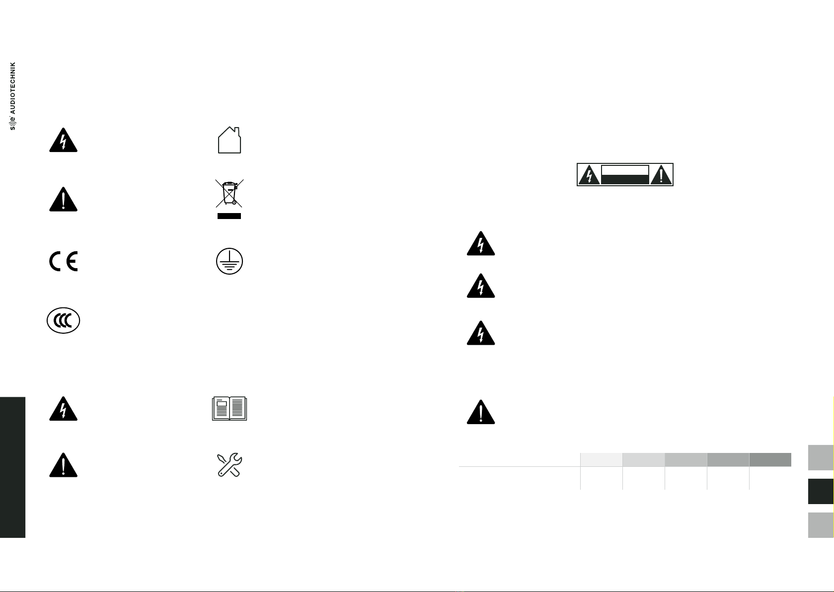
GRAPHICAL SYMBOLS ON THE PRODUCT
The lightning bolt triangle is used
to alert the user to the risk of
electric shock.
Symbol indicating that the
equipment is for indoor use only.
The exclamation point triangle is
used to alert the user to important
operating or maintenance procedures
and instructions.
Symbol for conformity with Directive
2002/96/EC and Directive 2003/108/EC
of the European Parliament, on waste
electrical and electronic equipment
(WEEE).
The CE mark indicates the conformity
with the relevant EU directives for
safety, health and environmental
protection. See the Manufacturer's
Declaration section.
Symbol for ground connection.
The CCC mark indicates the
conformity with the relevant
Chinese directives for safety,
health and environmental protection.
GRAPHICAL SYMBOLS IN THIS MANUAL
Symbol for important safety
information related with the
risk of electric shock.
Symbol for important concepts
and information for a better
understanding of the functioning
of the product.
Symbol to alert the user about
important operating or
maintenance instructions.
Symbol for practical tips and ideas
useful to ensure the correct use of the
product and improve its operation.

中文
EN
D
PACKAGE CONTENTS
98
IMPORTANT SAFETY INSTRUCTIONS
1. Keep these instructions.
2. Read these instructions.
3. Follow thoroughly all instructions.
4. Heed all warnings.
5. Do not use this apparatus near water.
6. Clean only with a dry cloth. Disconnect the device from the AC outlet before cleaning.
Do not use paint thinners, solvents, cleaning uids, or chemical-impregnated wiping cloths.
7. Do not block any ventilation openings. Install in accordance with the manufacturer's instructions.
8. Do not install near any heat sources such as radiators, heat registers, stoves, or other apparatus
(including ampliers) that produce heat.
9. Do not defeat the safety purpose of the grounding-type plug. A grounding-type plug has two blades
and a third grounding prong. The third prong is provided for your safety. If the provided plug does
not t into your outlet, consult an electrician for replacement of the obsolete outlet.
10. Protect the power cord from being walked on or pinched particularly at plugs, convenience
receptacles, and the point where they exit from the apparatus.
11. Unplug this apparatus during lightning storms or when unused for long periods of time.
12. Use the mains plug to disconnect the apparatus from the mains.
13. Keep away from objects which may be impaired by an external magnetic eld. To avoid the
damage of equipment such as computers, video monitors and magnetic data carriers, they
should be located at least 1 meter away.
14. Only use safety pins, attachments, accessories and adapters specied and/or provided by the
manufacturer.
15. Refer all servicing to qualied service personnel. This is required when the product has been
damaged in any way, such as power-supply cord or plug is damaged, liquid has been spilled
or objects have fallen into the apparatus, the apparatus has been exposed to rain or moisture,
does not operate normally, or has been dropped.
16. Do not insert your ngers, hands or any other foreign objects into any gaps or openings of the
device.
17. When this product reaches its end of life, take it to a collection point designated by local authorities.
The separate collection and recycling of your product at the time of disposal will help conserve
natural resources and ensure that it is recycled in a manner that protects human health and
environment.
PACKAGE CONTENTS
The packaging of the IC columns includes:
- 2 x IC 32, IC 34 or IC 38X speakers
- 2 x SMB (Smart-Mounting Brackets)
- 2 x Phoenix MSTB 4-pin connectors
- 1 x QC PASS card
- 1 x warranty card
The packaging of the subwoofer includes:
- 1 x S 112i PRO installation subwoofer
- 1 x AC power cord with powerCON® connector
- 1 x QC PASS card
- 1 x warranty card
The packaging of the IA system ampliers includes:
- 1 x IA 202D or IA 402D amplier
- 1 x AC power cord with C13 connector
- 1 x QC PASS card
- 1 x warranty card
Please inspect your product packaging before unboxing it. If it has been damaged during shipping,
unbox the product and check for any visual damage before using it. Notify the shipping company
immediately and contact your SE AUDIOTECHNIK® dealer or support center for help and assistance.
Finally, save the shipping carton as evidence for the possible claim, which can be requested only by you.
We also recommend you to keep all the packing materials and contents for any further transportation.

中文
EN
D
INTRODUCTION
1110
INTRODUCTION
The I-Line is a set of products designed for xed installations with ambitious requirements regarding
aesthetics, speech reproduction and music playback. No matter if you want to ll a conference room, the
sales area of a shop or a bar with sound: the I-Line oers you freedom of choice to compose a setup which
suits your needs best.
The line comprises column speakers, an installation subwoofer and two system ampliers:
- IC 32: The smallest column comprising 2 x 3.5" neodymium magnet woofers.
- IC 34: Middle-sized column comprising 4 x 3.5" neodymium magnet woofers.
- IC 38X: The largest column comprising 6 x 3.5" neodymium magnet woofers and
2 x 3.5" coaxial woofers with 0.5" compression drivers.
- S 112i PRO: The self-powered 12" subwoofer for installation with user controllable DSP.
- IA 202D: dedicated I-Line 200 W class-D power amplier with controllable DSP.
- IA 402D: dedicated I-Line 400 W class-D power amplier with controllable DSP.
INTENDED USE
The IC 32, IC 34 and IC 38X are column speakers designed for sound reinforcement in small to medium-
sized venues. Conceived for xed installation systems, they are suitable for applications where high SPL
and intelligibility are key. Their acoustic design allows for wide horizontal directivity reaching broad
audience areas as well as a narrower vertical directivity, depending on the columns installed.
The use of the IA 202D and IA 402D ampliers allows to implement systems composed by several
columns. This includes the possibility of having several secondary systems delayed to cover bigger venues.
In addition, the bandwidth of these powerful columns can be extended in the low frequency with the
S 112i PRO subwoofer. Specially designed for installation, this active subwoofer can be used to enhance
the capabilities of the system, mainly in applications involving music reproduction.
The ampliers and the active subwoofer include factory presets individually congured to assure the right
coupling between I-Line products.
Please, read thoroughly the Wiring and Installation and Applications sections for further information about
the setups, deployment and possibilities of the I-Line products.
Figure 1. I-Line products.
IC 32 IC 34 IC 38X S 112i PRO IA 402D
IA 202D

中文
EN
D
I-LINE PRODUCTS
INPUT
SELECT ION
INPUT
SELECT ION
IMPED ANCE: 4
Ω
POWE R HANDLING : 400W
WEIGHT: 7kg
INPUT
SELECTION
INPUT
SELECT ION
INPUT
SELECT ION
IMPED ANCE: 4
Ω
POWE R HANDLING : 400W
WEIGHT: 7kg
INPUT
SELECTION
5
4
3
1
2
1
INPUT
SELECT ION
INPUT
SELECT ION
IMPED ANCE: 4
Ω
POWE R HANDLING : 400W
WEIGHT: 7kg
INPUT
SELECTION
1
2
3
4
1
1312
REAR PANEL
1 Input/Link Phoenix MSTB 4-pin connector/s.
2 Input selection switch. Selecting input signal between +/-1 and +/-2.
3 Main bracket mounting position.
Allows for horizontal and vertical orientation in IC 32 and IC 34 columns.
4 Mounting point of safety wire.
5 Additional bracket mounting position.
Figure 2. Rear panel. IC 32 (left), IC 34 (center) and IC 38X (right).
I-LINE PRODUCTS
IC 32 / IC 34 / IC 38X
The IC 32, IC 34 and IC 38X conform the column speakers of the I-Line, equipped respectively with two,
four and six high-performance 3.5" neodymium drivers. In addition, IC 38X contains two 3.5" coaxial
woofers with 0.5" exit and 1" voice coil tweeters. A custom designed basket with advanced cooling module,
paired with a high-end paper membrane, enables these transducers to reproduce a wide frequency band
with high delity.
Furthermore, the speakers are properly aimed left and right alternately, in order to provide an optimal
horizontal high-frequency coverage. The IC columns come in brushed aluminum housings and their
slim and subtle appearance makes them blend well into many dierent environments.
When it comes to installing, you can mount the system speakers almost anywhere and at any desired
orientation by utilizing for IC 32 and IC 34 the proper Smart-Mounting-Brackets SMB, and SMBX for the
IC 38X columns. Both IC 32 and IC 34 speaker models have two 4-pin Phoenix connectors with accom-
panying channel switch, while IC 38X has only one on the bottom. These connectivity options make the
wiring process as easy and cost-ecient as possible, also minimizing the total required cable length.
Features
- Wide 120° horizontal coverage
- Compact and high SPL output
- Easy setup using SMB and SMBX bracket
- Aesthetic design
- Available in black and white

中文
EN
D
I-LINE PRODUCTS
1514
S 112i PRO SUBWOOFER
The S 112i PRO is an active subwoofer designed specially for the I-Line family. It is composed by a single
12" driver in a bass-reex conguration, powered by an updated 800 W Class-D amplier. Furthermore
and compared to previous developments, its improved enclosure design reduces port-noise and
maximizes system SPL.
Integrated DSP-presets enable dierent system setups to be used with various IC 32, IC 34 or IC 38X
congurations. Additionally, its ecient design and compact size guarantees safe, discrete and versatile
placement, oering also an aesthetic appearance for installation applications.
Features
- Ultra-compact subwoofer, weighing only 23 kg
- Increased SPL with reduced port-noise than predecessors
- DSP-Presets for easy subwoofer setup
- Built-in DSP and 800 W of class-D amplication
- Simple to use LCD screen and rotary encoder controller
- Eight-points ying points for safe and easy installation
- Wide range of supported applications with IC column speakers
- Available in black and white
REAR PANEL
1 Indicator LEDs:
Protect: Lights red if the amplier has short-circuited or overheated, which will be muted
automatically. Upon reaching normal operating conditions, the device reverts to normal
operating mode after a few seconds.
Limit: Lights red when the limiter starts working. If the limiter LED lights up permanently or
for longer periods, the gain level should be reduced. Failure to do so may result in a
distorted sound.
Signal: Lights green as soon as an audio signal is present. The input signal monitoring is performed
before the Main Level controller.
Power: Lights green once the system is properly connected to the mains power and switched on.
2 Alphanumeric LCD for DSP display.
3 Rear panel heatsink.
4 Power In. powerCON® type-A mains power socket. An appropriate power cable is included in the
package. The amplier is intended for two operating voltage ranges: 100-120 and 200-240 VAC.
The electrical conversion is done automatically.
5 Power Out. powerCON® type-B mains power output to link power between several units in the line.
The recommended maximum quantity of units to be connected in series is 4 units for
200-240 VAC mains, and 2 for 100-120 VAC.
6 Master control. Rotary encoder with push button for DSP control.
7 Line In. Balanced line-level input with female Neutrik® XLR-3 connector to connect input signal.
It allows input levels up to +20 dBu.
For an optimal signal-to-noise ratio, it is recommended to input signals with a level of at least
0 dBu.
8 Line Out. Balanced and buered line-level output with male Neutrik® XLR-3 connector.
It shall be used to link other components of the system, as additional S 112i PRO subwoofers.
9 Power. Switch to turn the unit on and o.
To avoid clicks and pops, turn on your PA system last and turn it o rst before other connected
devices. Additionally, after turning the unit o, wait for more than ve seconds before turning it
on again.
7
6
8
9
4
3
2
1
5
Figure 3.
S 112i PRO subwoofer rear panel.

中文
EN
D
I-LINE PRODUCTS
1716
IA 202D / IA 402D
I-Line oers two 2-channel class-D power ampliers with switching mode power supply. IA 202D delivers
2x 250 Watts at 8 Ω, while IA 402D provides 2x 400 Watts at 4 Ω.
Each amplier is equipped with a digital encoder with push button for DSP and preset selection. Our e-
cient DSP engine brings the exibility to load speaker presets, adjust parametric EQ, delay, lter, gain and
polarity settings thus helping with quick and easy system optimisation and sound tuning.
Sensor-controlled fan and optimized front-to-back airow, together with very low idle power consumption,
ensure low noise levels for quiet environments at all times. Finally, a combination of XLR-3, speakON® and
Phoenix connectors for in- and output signal, ensures maximum exibility during the installation process.
Features
- Two-channel power ampliers with switched supply
- Low noise and ecient heat dissipation with fan-aided airow system
- IA 202D: 250 W of class-D amplication
- IA 402D: 400 W of class-D amplication
- DSP-Presets for easy system setup
- Simple to use LCD screen and rotary encoder controller
- Dierent types of connectors for versatile connectivity
- Wide range of supported applications with IC column speakers
FRONT PANEL
1 Alphanumeric LCD for DSP display.
2 Master control. Rotary encoder with push button for DSP control.
3 Cooling fan. Air intake of sensor-controlled fan.
4 Air-intake vents.
5 Power. Switch to turn the unit on and o.
REAR PANEL
1 AC power connector. mains power socket. An appropriate power cable is included in the package.
The amplier is intended for two operating voltage ranges: 100-120 and 200-240 VAC. The electrical
conversion is done automatically.
2 Fuse.
3 Cooling fan. Air intake of sensor-controlled fan.
4 to 6 SpeakON® Outputs. From left to right, channel A, A&B and B.
7 to 9 Phoenix Outputs. From left to right, channel A, A&B and B.
10 and 12 Balanced Line In. Balanced line-level input with female Neutrik® XLR-3 connector to
connect input signal in channels A and B respectively.
11 and 13 Balanced Line Out. Balanced and buered line-level output with male Neutrik® XLR-3
connector for channels A and B respectively. It shall be used to link other components of
the system, as additional S 112i PRO subwoofers.
14 and 16 Unbalanced Line In. Unbalanced line-level input with 4-pin Phoenix MSTP connector,
to connect input signal in channels A and B respectively.
15 and 17 Unbalanced Line Out. Unbalanced line-level input with 4-pin Phoenix MSTP connector
for channels A and B respectively.
1 2 3 4 5
1
2 3 7 8 9 14 15 16 17
4 5 6 10 11 12 13
Figure 4. Front panel of the IA 202D I-Line amplier.
Figure 5. Rear panel of the IA 202D and IA 402D system ampliers.

中文
EN
D
WIRING AND INSTALLATION
1918
WIRING AND INSTALLATION
WIRING
Each IC column system and IA system amplier has clearly marked pinout for inputs and outputs.
Please follow the marking to ensure proper wiring for your system, as shown in gure 2.
Also, ensure to use cables with sucient cross-section to avoid energy-losses. It is recommended to use
cables with at least 18 AWG conductor size. For long cable lengths, the maximum conductor size is 14 AWG.
Figure 6. Phoenix MSTB 4-pin connector wiring.
The S 112i PRO subwoofer uses powerCON® connectors for the mains power input and link.
Figure 7 shows how to plug-in and connect these wires.
Conversely, audio signals in the IA ampliers can be output through a speakON® connector. These wires
should be connected as shown below:
Finally, the S 112i PRO subwoofer and the IA system ampliers can input and link audio signals through
XLR-3 connectors. They follow the next plug-in and conguration scheme:
INSTALLATION
Each of the IC 32 and IC 34 columns includes its own Smart-Mounting Bracket SMB, and the IC 38X an
its dedicated SMBX. These permit great mounting exibility and safety. Designed by German engineers,
the bracket has a maximum loading capacity of 10 kg. It can be individually adjusted on both axes,
reaches ± 90° in all directions by steps of 10°, and is suitable for ceiling and wall mount.
The IC 32 column has one single centered point where the SMB can be attached both horizontally or verti-
cally. This allows orienting them properly to match architectural requirements and t aesthetically
in the room.
Figure 7. powerCON® plug-in and link cable connection.
powerCON IN powerCON 1
L
L
N
N
powerCON OUT powerCON 1
Connection Wiring Scheme
L
N
2
1
Figure 8. speakON® plug-in and link cable connection.
speakON NL4 speakON 1 speakON 2
Connection Wiring Scheme
2
1
1+ 1+
2+ 2+
1- 1-
2- 2-
XLR-3 IN
Click Click 2 21 1
3 3
XLR-3 OUT
Connection
XLR-3 Female
Shield
Cold
Hot
XLR-3 Male
Wiring Scheme
Figure 9. XLR-3 plug-in and cable connection.
Figure 10. Mounting possibilities in the vertical plane for IC 32 with SMB in the center points.
6
0
.
0
°
4
0
.
0
°

中文
EN
D
WIRING AND INSTALLATION
3
0
.
0
°
2120
Figure 11. Mounting possibilities in the vertical plane for IC 34 with SMB in the middle mounting position.
Figure 13. Dierent aiming angles in the horizontal plane with the SMB bracket.
Figure 12. Mounting possibilities in the vertical plane for IC 34 with SMB in the bottom mounting position.
In addition to the multiple options available in the vertical plane, the SMB or SMBX bracket allows wide
angles in the horizontal direction, leading to increased exibility as shown below.
The S 112i PRO subwoofer includes eight ying points: two up on each side and four on the top.
These are steel M10 screws, which allow great versatility when installing the subwoofers.
2
0
.
0
°
To use optimally the narrow vertical directivity of the IC 34 and IC 38X columns, the SMB or SMBX bracket
can be placed only in this direction, but from two dierent points: one located in the center and the other
in the bottom. Please refer to gure 11 for middle mounting position and gure 12 for bottom mounting
position.
1
0
.
0
°
6
0
.
0
°
6
0
.
0
°
7
0
.
0
°

中文
EN
D
LCD PLATE AMPLIFIER
2322
LCD PLATE AMPLIFIER
The S 112i PRO installation subwoofer is equipped with a built-in 48 kHz/24 bit DSP processor, that
provides controlled signal processing and limiting. This DSP core is fed by dual-range inputs to improve
the Signal to Noise Ratio, and is easy to manipulate thanks to the rotary control encoder with push
button, and the 4x20 symbol alpha-numeric LCD screen.
This section details the features of the DSP rmware, whose adjustable parameters and features include
5 EQ bands, delay, polarity, high-pass and selection of low-pass lters. A variety of factory presets is also
available to easily setup dierent systems and in addition, the S 112i PRO subwoofer includes also
directivity control function.
The IA 202D and IA 402D system ampliers include also a 48 kHz/24 bit DSP processor with
the same parameters, so the following instructions can be used for them as well.
The instructions for the DSP Settings describe the functioning of the single channel of the
S 112i PRO subwoofer, but apply independently for the channels of the IA ampliers: A, B and
A+B. The System Settings are common for all three products.
Some key cursors, symbols and considerations used throughout the menu structure are:
- The rst line of each screen is the specic name or title of the given screen.
- The cursor ">" marks the current point of action.
- When editing preset names, the cursor "←" indicates deleting function.
- The symbol "*" highlights the selection of a given preset or setting. It indicates also that the edition
of a given parameter is enabled.
- The symbol "L" indicates the lock state of the amplier and thus, that editing any parameter is
not possible. This symbol appears only when this is activated, and only within the Overview screen.
Figure 14 details the dierent menus and functions of the DSP rmware, detailed in the following
subsections. Conversely, gures 19 and 34 show respectively the functions included in the DSP Settings
and System Settings.
OVERVIEW
MENU
DSP SETTINGS SYSTEM SETTINGS
Push Push 3sTurn & Push
Mute/Unmute Current
Conguration
Output Level
Turn
Figure 14. DSP rmware functions and menus.
OVERVIEW SCREEN
The Overview screen is the one shown by default on the amplier LCD, during normal operation
(Figure 15). It details the next information:
OVERVIEW
IN:
OUT:
GR:
-10
-02
12
>>>>>>>>
>>>>>>>>>>>
654321dB
Figure 15. Overview screen.
- The rst row shows the title of the screen and if applicable, the "L" letter in the top right-corner,
informing the lock state of the amplier.
- The second row shows the letters "IN:", followed by a numerical input level meter. The meter shows
the current input level value in dBFS, with minimum "-90" for low or no signal. The ">>>" symbols
show the signal strength relative to the clipping point at 0 dBFS. The readout is replaced with text
"INPUT CLIPPING!" if the signal reaches or exceeds 0 dBFS. In such case, the screen backlight is
ashing to call the attention of the user.
- The third row shows the letters "OUT:" which are followed by the output level meter. This meter
shows current output level relative to the maximum amplier output. If the channel is muted,
the level display meters are replaced with the text "MUTED".
- The fourth row shows the gain reduction in dB "GR:" applied to the signal when the limiter threshold
is reached. When the value increases, new levels appear from right to left, according with the amount
of reduction applied.
Out Gain: -6.0 dB
Change: -3.0 dB
OUT:-08 >>>>>>>>>>>
GR: 6 5 4 3 2 1dB
Figure 16. Turning the encoder in Overview screen allows to change output gain.

中文
EN
D
LCD PLATE AMPLIFIER
2524
From the Overview screen, the following options can be executed with the Master Control rotary encoder:
- Turn left or right to adjust the output level (Figure 16). The output gain and the relative change in dB
are shown. The output level is always recalled and is not aected by any reset function.
- Turn one step and push to quickly mute or unmute the amplier output.
- Push (without turning) to open the Active Preset Info screen and see both the active preset and
the delay currently dened (Figure 17). Clicking "Back" will return to the Overview screen.
Letters "CA" after the name of the preset indicate that the cardioid directivity function is enabled.
End-re function is denoted as "EF" and normal radiation shows no additional letters.
- Press and hold 3 seconds to enter the MENU.
ACTIVE PRESET INFO
MF3AP : Default CA
USER DELAY:
0.64 ms > BACK
Figure 17. Active Presets View.
MENU
To enter the MENU of the amplier, press and hold the Master Control rotary knob for 3 seconds. A menu
as shown in Figure 5 will appear on the screen.
MENU
> DSP Settings
System Settings
Exit
Figure 18. Main Menu.
Two submenus can be accessed from this point:
- DSP Settings: signal processing settings such as presets, lters, EQ, delay are congured here.
- System Settings: power amplier operation settings are congured here.
Clicking "Exit" will return to the Overview screen.
DSP SETTINGS
DSP Settings menu is shown in Figure 19.
DSP Settings
Back
> Preset Libary
Highpass Filter
Lowpass Filter
Phase Inversion
EQ 1
EQ 2
EQ 3
EQ 4
EQ 5
Bypass User EQ
Delay
Reset User Params
Input Sensitivity
Exit
Figure 19. DSP Settings menu.
DSP SETTINGS > PRESET LIBRARY
Preset Library menu allows to load and save DSP processing presets. These are divided in two basic types:
- Factory presets: these are the default congurations for each SE AUDIOTECHNIK'S® speaker intended
to be used with your subwoofer, and contain the information about factory pre-dened lter and
limiter settings.
They are marked with an "F" letter at the right side of the preset. More details can be found in the
Factory Preset subsection of this manual.
- User presets: 8 custom congurations for the user to dene, using the factory presets as starting point
and saving additional adjustments, as:
- User High-pass lter settings
- User Low-pass lter settings
- User EQ settings
- User Delay settings
- User Phase Inversion (Polarity) settings
They are marked with a "U" letter at the right side of the preset name.

中文
EN
D
LCD PLATE AMPLIFIER
2726
As mentioned, the current loaded preset is marked with the "*" symbol.
PRESET LIBARY
Back
> MF3A
MF3A-P
GENERAL
EMPTY: USER 1
EMPTY: USER 2
FO
F
F
U
U
Figure 20. Preset Library menu.
The names of the presets are organized in such a way that the rst symbols will always refer the
loudspeaker model which the preset has been made from. This way the user knows what factory
preset was the origin of the custom user preset.
DSP SETTINGS > PRESET LIBRARY > PRESET LOADING
To load a preset, scroll to it and click the rotary controller. A dialogue is displayed on the screen to either
load preset, save preset or go back. By pressing "Load Preset", the preset is loaded in the DSP and the
message "Load Done" is displayed shortly on the screen.
To return to the Preset Library, choose "Back" and click the rotary controller.
FACTORY PRESET
MF3A : Default
Back
> Load Preset
Figure 21. Loading factory preset.
DSP SETTINGS > PRESET LIBRARY > PRESET SAVING
To save a preset, choose one of the existing or empty user preset locations and click the rotary controller.
A dialogue similar to factory preset loading is displayed on the screen but an additional option is available
to save the preset. Saving is only available in the user presets.
EMPTY: USER 1
Back
Load Preset
Save Preset>
USER PRESET
Figure 22. Saving user preset.
By clicking on "Save Preset", a dialogue to dene the preset name is displayed. By default, the rst
characters of the name are the same of the current loaded preset and these can not be changed.
Thus, before being able to setting and saving any user preset, a factory preset needs to be active.
To customize the name of the new preset, the user can edit the last symbols of the default name,
separated by the ":" symbol. To do this:
1. Set the cursor ">" on the name and click the encoder. The "*" symbol appears to indicate that
name edition is enabled.
2. Turn the controller to choose the character desired and x it by pressing the button. Character
deletion is performed by choosing the "←" symbol and clicking.
3. Complete the editing of the name by choosing the "space" symbol and then click twice.
To conrm, choose "Save" and click the rotary controller. The message "Save Done" is shortly displayed
on the screen. To return to the Preset Library, choose "Back" in the following two screens.
> MF3A : _Club__
Back
Save
SAVE USER PRESET
_
Figure 23. Saving user preset.
DSP SETTINGS > PRESET LIBRARY > PRESET INFORMATION
By pressing 3 seconds on the selected preset, a dialog shows up displaying various information about it.
In the latest rmware version, the Name, Date, Version and Author are displayed and shall be used to
ensure that the speaker presets are up to date.
> Back
MF3A : DLY Line U
Date: 20170629
Based-On: 0.6
Orig-Author: 02
PRESET INFORMATION
Figure 24. Preset information dialog.

中文
EN
D
LCD PLATE AMPLIFIER
2928
DSP SETTINGS > HIGHPASS FILTER
The Highpass Filter section allows to change cut-o frequency of the high-pass protection lter. The lowest
possible setting is an electrical 4th order, tuned for S 112i PRO at 36 Hz. This lter is always enabled.
All frequency steps above the lowest option correspond to an acoustical 6th order Butterworth lter.
These additional values are: 48, 50, 53, 56, 60, 63, 67, 71, 75, 80, 85, 90, 95 and 100 Hz.
Changing this cut-o frequency can be useful mainly when the S 112i PRO subwoofer is used with other
subwoofers that cover the lower frequency bands. To do this:
1. Set the cursor „>“ on the option „Freq“ and click the encoder. The „*“ symbol appears to indicate
that edition is enabled.
2. Turn the controller to choose the value desired and x it by pressing the button.
3. Choose „Back“ and click the rotary controller to return to the DSP Settings submenu.
HIGHPASS FILTER
> Back
Freq. : 36 Hz
Figure 25. High-pass Filter adjustment.
DSP SETTINGS > LOWPASS FILTER
The DSP of the subwoofer also includes an adjustable Lowpass Filter and this submenu allows to change
its type, slope and cut-o frequency, and to bypass it.
LOWPASS FILTER
> Back
Bypass: OFF
Freq: 120 Hz
Type: LR 24dB/Oct
Figure 26. Low-pass Filter adjustment.
The selection of the parameters is performed as explained for the Highpass Filter, and the options are:
- Bypass: On or O.
- Freq.: sets cut-o frequency (-3 dB) from 80 to 240 Hz, with 1 Hz steps.
- Type:
- Butterworth lters: BW 6 - 48 dB/Oct.
- Linkwitz-Riley lters: LR 12, 24, 36 or 48 dB/Oct
DSP SETTINGS > DIRECTIVITY (S 112i PRO ONLY)
Turning the control knob in the Directivity menu activates dierent directivity options in order to modify
the radiation of the S 112i PRO subwoofer. This function oers three options:
- Normal: no process is applied and the subwoofer behaves as an omnidirectional source.
For this mode, no additional information is shown in the Active Preset Info screen.
- Cardioid: it implements specic DSP processes to create a cardioid directivity pattern when used
properly in a subwoofer array. In this mode, the letters "CA" appear in the Active Preset Info screen.
- End-Fire: it enables end-re conguration by selecting a desired tuning frequency with the "Att. Freq"
parameter. This factor ranges from 40 Hz to 100 Hz, in 1 Hz steps.
By changing the attenuation frequency, the screen shows the necessary space between the front
grilles of the subwoofers to get the eect. Finally, when this mode is implemented, the Active Preset
Info screen shows the letters "EF".
DIRECTIVITY
Back
Type: End-Fire
> Att. Freq: 69 Hz
Sub Dist: 1.24 m
Figure 27. Example of an end-re setup in the Directivity menu.
Subwoofer arrays are able to control and aim the sound by introducing directivity in the
intended direction. The "Cardioid" and "End-Fire" congurations are two of the most common
setups.
The rst one uses typically three subwoofers aligned or stacked: two of them facing front or
towards the audience, and the other facing rear or towards the stage.
End-Fire setups use two or more subwoofers placed behind each other with a xed spacing and
- in some cases - dierent polarities. They provide very good rear-cancellation and are easy to
set up, but require more space to implement.
In both cases, a specic delay must be applied in order to achieve wave summation in the front,
and cancellation in the rear.
In cardioid setups, select "Normal" mode for subwoofers facing front, and "Cardioid" mode for
the one facing rear.
For end-re conguration, select "End-Fire" mode for the rst subwoofer and observe in the
screen, the distance calculated. Place the second subwoofer behind keeping that distance
between the grilles, and select "Normal" mode for the second subwoofer.

中文
EN
D
LCD PLATE AMPLIFIER
3130
DSP SETTINGS > PHASE INVERSION
PHASE INVERSION
Back
> Normal +
Inverted
Figure 28. Equalizer menu.
The Phase Inversion submenu switches the phase of the signal. In other words, it allows to invert or
„reverse“ its polarity. Two settings are available:
- Normal: In phase setting.
- Inverted: The phase/polarity is inverted by introducing a 180°phase shift to all frequencies.
Only for Parametric lters.
DSP SETTINGS > EQUALIZERS (EQ1 TO EQ5)
For system tuning purposes, 5 user-adjustable equalizers are available oering the following parameters:
- Bypass: On (the EQ is bypassed) or O (the EQ is active).
- Type: Low Shelf, Parametric or High Shelf.
- Gain: -12 to 12 dB, with 0.1 dB steps.
- Freq: 20 Hz to 1kHz, 1 Hz steps. Sets the center frequency for Parametric lters, or the edge frequency
for Shelf lters.
- Slope: 0.5 to 2, with steps of 0.1. Only for Shelf lters.
- Quality: 0.01 to 16 with steps of 0.01, where higher Quality Factor values mean narrower bandwidth.
Only for Parametric lters.
An example of a parametric equalizer with EQ1 in parametric mode is shown below.
EQ1
Back
Bypass: ON
Type: Parametric
> Gain: 6 dB
Freq: 60 Hz
Quality: 1.00
Figure 29. Equalizer menu.
To modify equalizer parameters, follow the same steps detailed in the Highpass Filter section.
Notice that the equalizers can be individually bypassed, their default setting.
DSP SETTINGS > BYPASS USER EQ
In order to compare the response of the subwoofer with and without the applied EQ, this section allows to
bypass all user EQs with a single click.
BYPASS USER EQ
Back
Bypass a l l +
Enable a l l
Figure 30. Bypass User EQ menu.
Remember that user EQs are bypassed by default and can be activated individually.
DSP SETTINGS > DELAY
The Delay section allows the user to apply a delay to the signal, visualize it in dierent units and determine
the total delay. This screen has the following three sections:
- User added delay: This is the delay dened or added by the user depending on the specic needs of
his application.
- Preset delay: Depending on the preset enabled or selected, the system may include an additional
delay. This delay is added by the current preset and for some factory presets, it can be also edited.
- Total DSP delay: Total sum of "User", "Preset" and internal DSP latency. It is not an editable parameter
and is only shown for information and reference.
The "User" and "Preset" delays can be dened in three dierent units, corresponding to the editable
parameters in the rst two delay sections:
- Samples: for 48 kHz sampling rate.
- Time: Delay in milliseconds (ms), referred to the 48 kHz sampling rate.
- Distance: Delay in meters (m), referred to c = 343 m/s.
When changing a parameter in any section, all the other parameters are updated with the corresponding
value in their units.

中文
EN
D
LCD PLATE AMPLIFIER
3332
DELAY
Back
User addad delay:
> Bypass: OFF
Samples: 0
Time: 0.00 ms
Distance: 0.00 m
Preset delay:
Bypass: OFF
Samples: 10
Time: 0.21 ms
Distance: 0.07 m
Total DSP delay:
Samples: 63
Time: 0.31 ms
Distance: 0.45 m
Figure 31. Delay menu.
The smaller "User" delay available for the S 112i PRO subwoofer is 1,232 samples, that corresponds
25.7 ms and approximately 8.8 meters of propagation delay. Depending on the factory preset selected,
the largest available is 1,380 samples, equivalent to 28.8 ms and 9.9 meters.
In the IA 202D and IA 402D ampliers, a delay of up to 700 samples can be applied to each
channel. In addition, it can be congured through the LCD that one channel uses all 1,400
samples.
DSP SETTINGS > RESET USER PARAMS
The Reset User Params submenu resets user DSP settings such as:
- High-pass lter
- Low-pass lter
- Equalizers
- Delay
- Phase Inversion
- Bypass user EQ
The Output Gain, Input Sensitivity and the Preset selected are not aected by this function.
Reset Channel A User
Parameters?
(DLY, EQ, Filters
Phase Inversion)
Back
> Reset
Figure 32. Reset user parameters menu.
By turning the controller, the options "Reset" or "Back" will appear. By choosing the rst one, the message
"Reset Done" is shortly displayed on the screen. To return to the DSP Settings, choose "Back".
DSP SETTINGS > INPUT SENSITIVITY
For more exibility and variability in installation applications, the input sensitivity can be adjusted by the
user both for the S 112i PRO and IA ampliers, depending on the signal source used. The screen shows
the dierent sensitivities available in dBu or dBV, and their corresponding values in volts.
Reset User
Parameters?
(DLY, EQ, Filter, PHA)
Back
> Reset
Figure 33. Input sensitivity menu.

中文
EN
D
LCD PLATE AMPLIFIER
3534
SYSTEM SETTINGS
The System Settings is the second submenu of the main MENU. It allows to set dierent parameters of the
amplier and access various system functions.
SYSTEM SETTINGS
Back
> LCD Backlight
LCD Brightness
Reset
SW Information
Lock
Menu Timeouts
Exit
Figure 34. System Settings menu.
SYSTEM SETTINGS > LCD BACKLIGHT
The LCD Backlight submenu congures the LCD screen’s backlight settings. There are two general choices:
- Auto O: Which will turn-o the backlight after 6 seconds by default. To set a dierent value:
1. Set the cursor ">" on this option and click the encoder.
2. Turn the controller to choose a value between 1 and 60 seconds. Pressing the button will x this
value and return the screen to the LCD Backlight submenu.
- Always On: Which sets the backlight to be always on.
LCD BACKLIGHT
Back
> Auto Off
Always On +
Figure 35. LCD Backlight menu.
SYSTEM SETTINGS > LCD BRIGHTNESS
The LCD Brightness screen enables to set the brightness of the LCD screen. To x a value, follow the same
procedure stated for the LCD Backlight submenu.
LCD BRIGHTNESS
Back
> 9 [0-15]
Figure 36. . LCD Brightness menu.
SYSTEM SETTINGS > RESET
The Reset function clears the current selections and sets the factory-default ones for the following settings:
- LCD Backlight settings
- LCD Brightness
- Lock settings
RESET SYSTEM
SETTINGS?
> No (Back)
Yes
Figure 37. Reset menu.
SYSTEM SETTINGS > SW INFORMATION
This screen shows the most relevant information about the amplier’s rmware, which can be important
not only for users but also for service technicians.
- MCU: Software version of the Micro Controller Unit.
- FW: Firmware version.
- Model: model of your SE AUDIOTECHNIK® product.
SW INFORMATION
Back
> MCU: 0.0.4.2
FW: 20170630
MODEL: S12 PRO
Figure 38. SW Information menu.

中文
EN
D
LCD PLATE AMPLIFIER
3736
SYSTEM SETTINGS > LOCK
In the Lock menu, the user can set one of the following options for the screen locking function:
- Automatic Lock: This option will lock automatically the amplier's screen after 10 seconds by default.
To set a dierent value, between 2 and 60 seconds, follow the same procedure described for the LCD
Backlight submenu.
- Lock Now: This option will lock the screen instantly. The selected settings for Automatic Lock or No
Lock, are kept.
- No Lock: This is the option set by default. It will disable the automatic lock function and make the
screen always accessible.
SCREENLOCK
Back
> Automatic Lock +
Lock now
No Lock
Figure 39. Screen Lock menu.
When the screen is locked, the letter "L" is shown in the top-right part of the Overview screen. To unlock
the amplier, press the controller for 3 seconds until the message "Screen Unlocked!" is shortly displayed
on the screen. This message details the active preset as well.
SYSTEM SETTINGS > MENU TIMEOUTS
In the Menu Timeouts, the preferred behavior of the main MENU can be congured according with the
options:
- On, jumping out: After 5 minutes of inactivity, the display returns to the Overview screen.
- O, stay in menu: the display stays in the current menu indenitely. This option is selected by default.
MENU TIMEOUTS
> Back
On, jumping out +
Off, stay in menu
Figure 40. Menu Timeouts menu.
FACTORY PRESETS
The list of available presets for the S 112i PRO subwoofer is shown below:
Preset Name Description
IC 32 When used together with IC 32 columns.
IC 34 When used together with IC 34 columns.
IC 38X When used together with IC 38X columns.
L 35 When used together with L 35 passive line array units.
GENERL. Preset for general purposes.
The presets included in the IA 202D and IA 402D ampliers are:
Preset Name Description
IC 32 Preset when powering IC 32 columns.
IC 34 Preset when powering IC 34 columns.
IC 38X Preset when powering IC 38X columns.
FLAT Preset for general purposes.
Finally, IA 402D ampliers include a wide range of factory presets to be used with L 35 units, an
ultra-compact passive line array system from SE AUDIOTECHNIK®. More information about these
can be found in the dedicated L 35 user manual, available in our website www.se-audiotechnik.de.
Factory presets provide natural sound and even frequency response between products in the
close distance.
If the preset library on your product diers from the list shown above, please check your rmware version
in the System Settings > SW Information menu and contact your dealer to update it.

中文
EN
D
APPLICATIONS
Input Source
(Mixer)
+/-A
+/-1
+/-B
+/-1
3938
APPLICATIONS
The I-Line products have been designed to match the needs of a wide-range of installation applications.
The column systems are being driven with IA system ampliers and S 112i PRO subwoofers provide
LF extension for full bandwidth. Depending on the application, the system can be used with or without the
subwoofer.
Due to air-absorption, a HF emphasis might be necessary for longer throw applications.
Typically, a high-shelf equalizer at 4-5 kHz and 3-6 dB boost can provide good results.
When mounted to the wall, low-frequencies are being boosted due to the coupling eect.
This may alter the LF response of the system, depending on the materials, proximity and
number of nearby surfaces. Mounting the speaker in the corner, close to the ceiling or in
the middle of a wall will provide various amounts of LF boost. To balance it, a low-shelf
equalizer can be used.
Following, some of the most common setups are shown - but depending on your application, many
dierent congurations can be implemented.
It is important to keep in mind that the amount of drivers in the passive columns, is duplicated from one
model to the next. Level-wise, this allows to state the following SPL equivalences:
1x IC 38X = 2x IC 34 = 4x IC 32
In addition and again in terms of the SPL level produced, each of these quantities will match one
S 112i PRO subwoofer.
Of course, all this is valid only when the corresponding presets are chosen, both in the IA I-Line ampliers,
and in the S 112i PRO subwoofer.
MEETING ROOM
Features Events
-
-
-
Wide bandwidth with minimum components
Great intelligibility for speech reproduction
Easy and safe to install and setup
-
-
-
Meetings
Study rooms
Projections for reduced audiences
Components Presets / Adjustments
-
-
-
2 x IC 34 Column speakers
2 x SMB Smart Mounting Bracket
1 x IA 202D System Amplier
-
IA 202D system amplier:
IC 34: Default preset
Figure 41. Schematic of Meeting Room Example.
This manual suits for next models
6
Table of contents
Other SE Audiotechnik Speakers System manuals
Popular Speakers System manuals by other brands

Electro-Voice
Electro-Voice Dual 15-InchTwo-Way Full-Range Speaker System Force... Technical specifications

Definitive Technology
Definitive Technology W Studio Micro Setup guide

GoSpeak
GoSpeak SMK-Link’s user guide

Element
Element ESBAB20RTR user manual

Electro-Voice
Electro-Voice Variplex II Technical specifications

Electro-Voice
Electro-Voice S-1202ER datasheet