Bengtson FOKKER DVII User manual
FokkerDVII36”
Copyright©2005‐11M.K.BengtsonAllRightsReservedRev07/11
FOKKERDVII
R/CScaleModelInstructions
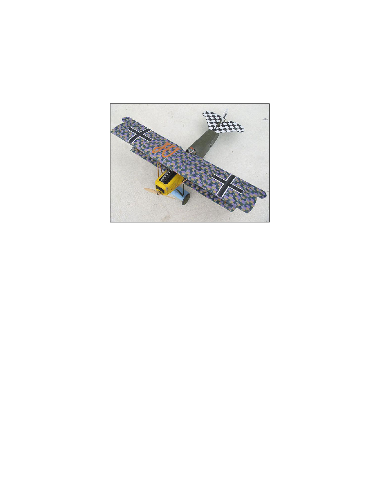
FokkerDVIIbyBertAyers
CONTACTINFORMATION
TheFokkerDVIIwasdesignedbyM.K.Bengtson
ManufacturedandDistributedby:
BengtsonCompany
WebSite:www.aerodromerc.com

FokkerDVII36”Page2
Copyright©2005‐11M.K.BengtsonAllRightsReservedRev07/11
FokkerDVII
ThankyouforpurchasingtheFokkerDVIImodelfor
electricflight.AsemiscaleadaptationoftheFokkerDVII,
thismodelisdesignedtobeeasytobuildandexcitingto
fly.
POWERSETUP
TheSpeed400motorpowersthemodelandtheMini‐
Olympus2.33:1gearboxanda10x6APCprop.Battery
powerpackcanbe8x600maHNicadsoranequivalent
weightNimh
SPECIFICATIONS
Morethan200lasercutparts
Scale: ~1/9
Channels: R/E/A/TorR/E/T
Wingspan: 36ʺ
WingArea: 318sqin
Weight: 25ozreadytofly
PowerSystem:Speed400,Mini‐Olympus2.33:1gearbox
Prop: 10x6
Wheels: Balsa&plywood,Neoprenefoamtires
AirfoilType:Flatbottomed,nearlyscaleshape
Cowl: Builtupbalsa
Spinner:N/A/
Decals: Availableonwebsite
BEFORESTARTING
Anoteaboutthephotos:Thephotosweretakenofa
prototypeandthepartssuppliedmaylookslightly
differentfromthem.However,theconceptsillustrated
arethesame.RoddPerrinbuilttheprototype.
WINGS
TheDVIIhadanunusualwingprofilelookingfromthe
noseoftheaircraft.Thewingribstaperedinheight
towardsthetipandhadthetopofthewinglevel(the
bottomofthewingcurveduptogiveanapparent
dihedral).Themodel’stopwinghasthecorrecttaperin
theheightoftheribswiththetopofthewingbeing
straightandthebottomtaperingupatthetips.
Similartothebottomwing,thetopwingismadefrom
twopanelswithacentersection.
Thetrailingedgescanbesandeddownversionsofthe
templatessuppliedinthekit.Alternately,use¾”trailing
edgestockandusethetemplatesasaguidetosandthe
scallopsinthebackedge.Apieceofsandpaperwrapped
aroundasuitablecylinderorbottlemakestheperfect
sandingtool.Thismethodsavesalotonsandingtime.
TopWing
Thetopwingcanbevirtuallybuiltupbeforeanyglue
needtobeapplied.
TheLeftTopWing
TheplansshowthepartsforboththeR/EandR/E/A
versionofthetopwing(moredihedralintherudder/
elevatorversionanddifferentribsforwheretheailerons
aresituated).
TheaileronsfortheDVIIareonlyonthetopwingandare
relativelysimpletomake.
Apre‐cutwingtip,leadingedgesparandribsmakethe
jobeasy.
TheLeftAileron
WingIPStrutAttachmentPointDetail

FokkerDVII36”Page3
Copyright©2005‐11M.K.BengtsonAllRightsReservedRev07/11
ThewingIPstrutsarerecessedintoslotsintheupper
portionof1/8”ribs.Somescrap1/8”balsasandedto
matchtheribprofilereinforcestheseslots.
Withtherightandleftwingpanelsfinished,itistimeto
jointhetwoviathecentersection.
Beforejoiningthepanels,aquickcheckwiththesteel
rulertomakesureeverythingisaligned.Sightingdown
thelineofthetopspar(1/16x1/8bass)withthesteelruler
insertedintheholeforthetopspar
CheckTopSpar
SightingDowntheLineoftheTopSpar.
Theaileronjoinsthewingatanangletothetrailingedge.
Thismeansthattheaileronservo,whichneedstobeat
rightanglestothedirectionofaileronmovement,also
needstobeatanangletoavoidbinding,etc.
LowerWings
TheLowerWing
LowerWingSheeting
Theinnertworibbaysaretopsheetedwith1/16”balsa.
Thefinalsandingwillremovethesparextendsbeyond
theendoftherib(sodoesthesheetingforthatmatter!).
WingsCompleted
Fuselage
Thefuselageisa1/8thbalsaforwardsectionwithabuilt
uptailarea.Thisproducesafuselagethatisbothlightand
strongandiseasytomakestraight.
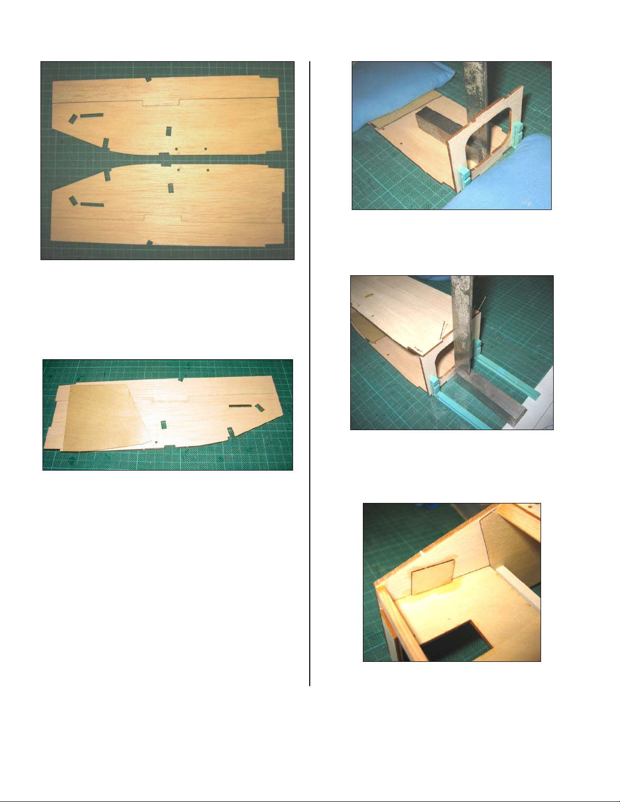
The1/8thsectionismadefromtwopiecesofbalsa.They
arekeyedtoensurethatthefuselagesidesareassembled
correctly.Thisisespeciallyimportantasthecabanestrut
cutoutsarealreadyinthefuselageside.
FokkerDVII36”Page4
Copyright©2005‐11M.K.BengtsonAllRightsReservedRev07/11
ForwardFuselagePre‐glue
Makesureyouallowthemtodrythoroughlybefore
movingthemfromthebuildingboard.Alightsanding
doneatthisstagewillgetridofanyjointline.A1/32”ply
doublerisnextplacedoverthemiddlesectionofthe
fuselage.
1/32”PlyDoubler
Theplansshowwherethisshouldgo,butitcanbeputin
thewrongspotifcareisnottaken.
Atthisstagealeftandrightsidearemade,somarkeach
sideappropriatelybeforecommittinganygluetothe
model.
Uselightpencillinestomarkwherethedoublerneeded
togotomakesurethatglueisnotspreadeverywhere.
Afterwaitingforthegluetotack,weightbothsidesdown
withleadshotbags(andsomeplasticwraptomakesure
theydon’tsticktogether)forthegluetodry.
Oncethefuselagesidesaredry,theformerscanbe
attachedtooneside.
RearFormerisBeingGluedtoOneSide
Similarly,thefrontformerisgluedtotherightside.
NoteRoddʹsextensiveuseofweightsandsquarestomake
sureeverythingisalignednicely
Oncetheglueisniceanddry,thetwosidesarebrought
together.
Addthe1/32”plycabanestrutmountingreinforcements
insidethefuselage.
1/32”PlywoodCabaneStrutMountingReinforcements
FokkerDVII36”Page5
Copyright©2005‐11M.K.BengtsonAllRightsReservedRev07/11
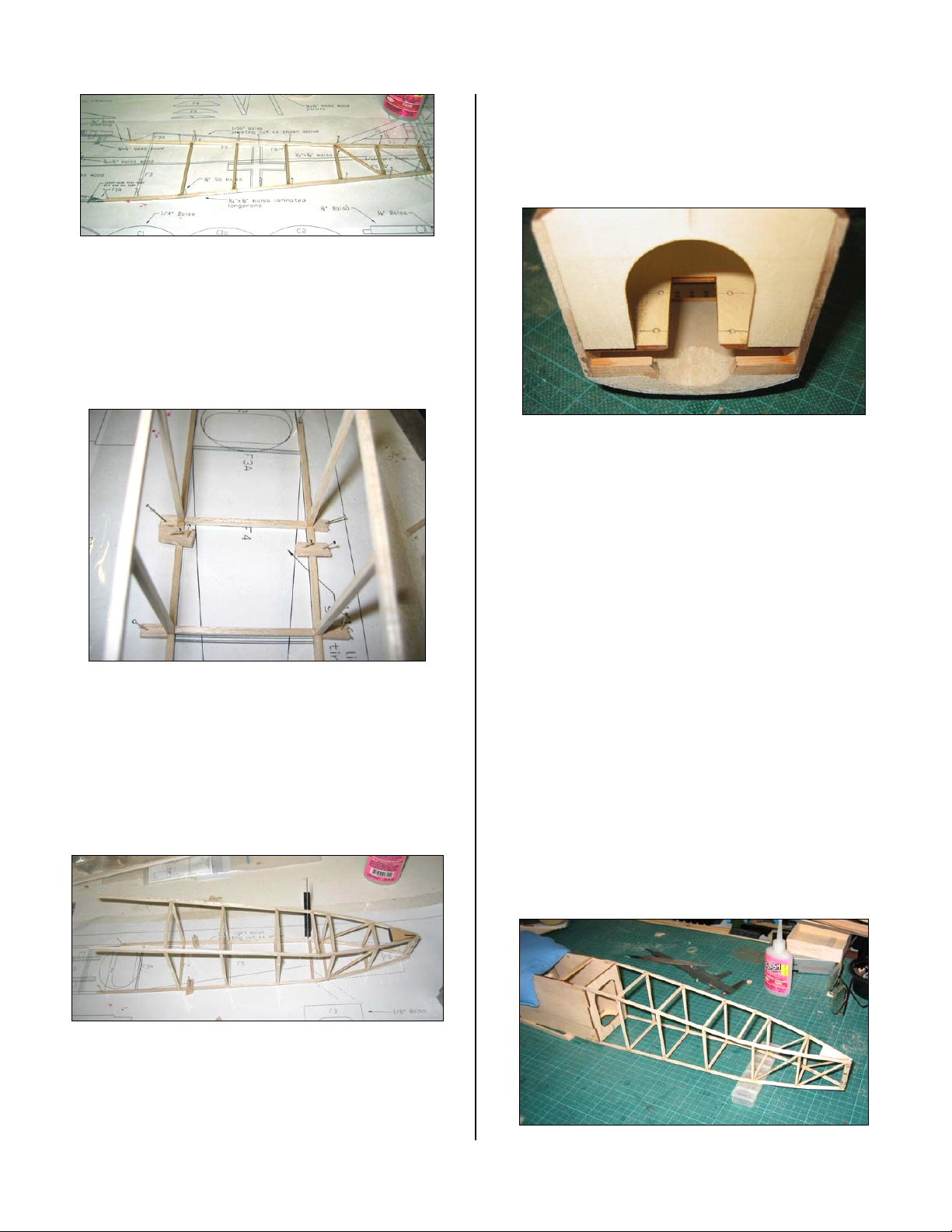
RearFuselageConstructionDetail
Therearfuselageismadefrom1/8thsquarebalsasticks.
TheDVIIshouldhavethelongeronsmadefromhard
balsa(butnotbulletproofbalsa!).
Thefirstsideisbuiltovertheplan,withthesecondside
beingbuiltoverthetopofittogivetwoidenticalsides.
Bitsofcoveringbackingpreventthesidessticking.
ScrapBalsatoHoldthe1/8thSquareFlattotheBuildingBoard
Roddusedsomescrapbalsatoholdthe1/8thsquareflat
tothebuildingboardsohedidnothavetopinthrough
thelongeronsandweakenthem.
Witheachsidealignedtotheplan,thecrossmemberscan
starttobegluedintoplace.
Whencuttingthecrossmembers,cuttwoatatimesothey
willbeidentical.Thiswaytheyarebothright.
RearFuselage
Theblockofbalsaatthetailisforthelandingskid.
Addasmallbitif1/8thsquarebalsa,suitablytaperedtofit
betweenthetwoendpostsofthefuselage,tomakethe
rearjointniceandfirm.
Asthereisamajorchangeintaperintherearfuselagejust
underthetailplane,smallcutsweremadeintotheinside
ofthelongeronswherethechangeintaperislocated.Bits
of1/8thsquarebalsasupportsthejoint.
MotorMount
Insertthemotormountbeforethefrontofthemodel
becomestoostifftoallowittobepoppedintoplace.The
motormountispre‐cutforaS400Mini‐Olympuswith
somesidethrustalsobuiltin.Makesureitgoesintogive
rightthrust.Theparthasmarkedwhichwaygoesup.
Themotormounthastwowingsoneachside,whichfit
intocorrespondingslotsinthefuselage.
Thecowlsupportcrossmemberisgluedintoplaceafter
themotormountisinstalled.
Withthefrontfuselageessentiallycompleteandtherear
fuselagecomplete,itisnowtimetobringthetwo
together.
Atthisstage,donotaddanyoftheupperformerstothe
frontfuselagetomakeiteasiertosetthingsupflat.
Thefrontfuselageisweighteddowntothebuildingboard
andtherearfuselagealignedintotheslots.
UnlikesomeBritishaircraft,theDVIIdoesnothavea
straighttoplongeron.Bitsfromaroundtheworkshopare
usedtopropuptherearfuselagetogettherightchanges
inslope.Checkthatthestructureissquare.
FokkerDVII36”Page6
Copyright©2005‐11M.K.BengtsonAllRightsReservedRev07/11
RearFuselageDetail
TIP:Putlittlemarksalongthecenterlineofformers,etc
whichwillsignificantlyhelpthejoiningprocess.
Thesecrettoastraightfuselageistoholdoneendfirmly
whileallowingtheotherendto‘float’alittle.Thisensures
thatthepartsdofitintoplacewithouthavingtobeforced
tofit.
Thetopfuselageformersweregluedintoplaceandalso
downtherearfuselagetosupporttheturtledeck.
Roddusedpapertomakeupatemplatetoavoidwasting
balsa.
Thetemplatewasmadeslightlyoverlong,withoneend
15mmwideandtheotherexpandingto86mmwherethe
rearfuselageformerwaslocated.Anyoverhangwas
sandedoffwhentheturtledeckwasgluedtothefuselage.
FuselageTemplate
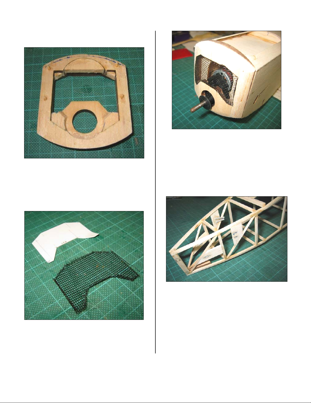
Thecowlneedstobeconstructednext.
Thecowlismadefromthreepiecesofbalsa–two1/4”
andone1/8”Thethinonegoesinthemiddle.
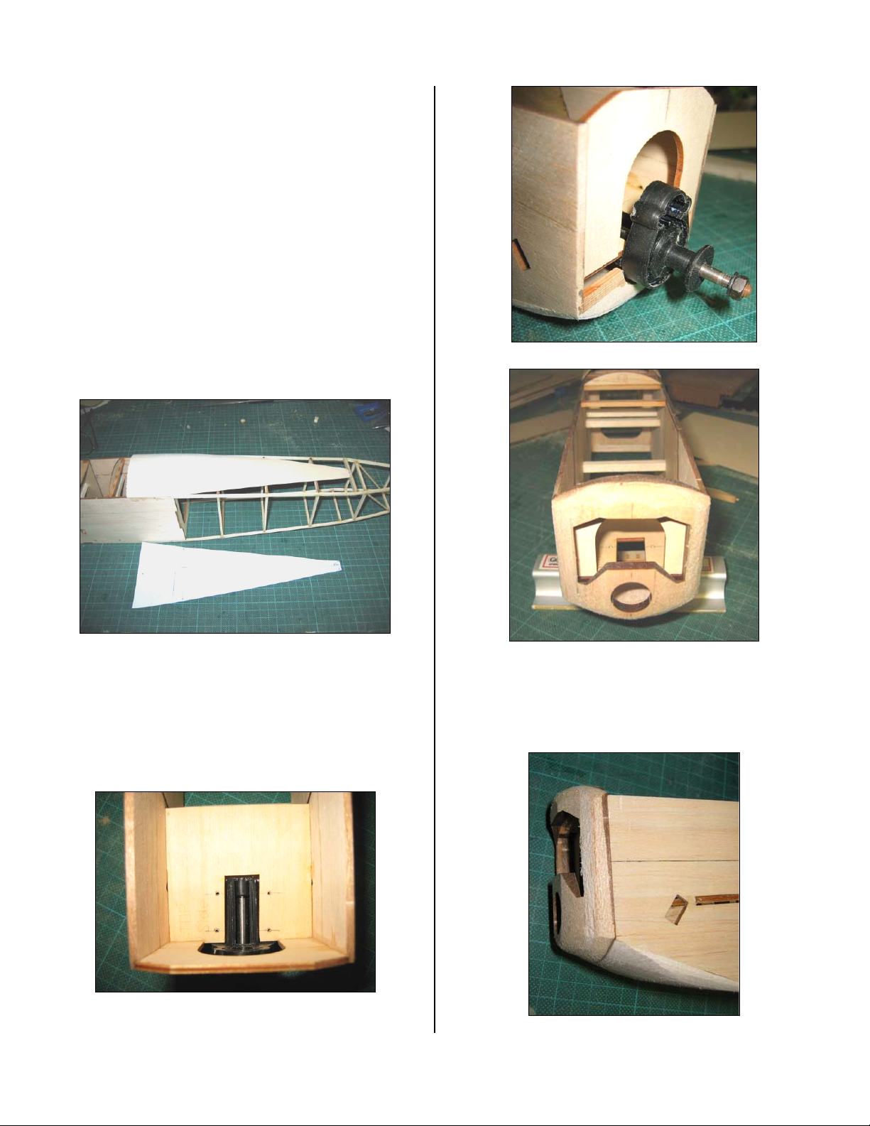
Thegearboxmustsitdownonthemotormountingplate,
sorelievethefrontbracealittleandgougeoutasmall
groveinthenosehatch.
GearboxDetail
Gearboxinplace
Cowl
Theradiatorwasthentackgluedintoplaceonthenose
androughlysandedtoshapetomatchtheDVIIdrawings.
Lookingfromthetop,theradiatorshouldhaveashape
approximatelylikeaflatbottom‘v’.
Rough‐SandedNosefromtheSide
FokkerDVII36”Page7
Copyright©2005‐11M.K.BengtsonAllRightsReservedRev07/11
Toprovidealittlesupport,Roddgluedsomescrapbalsa
intothethinnedareasforadditionalsupport.
BackofCowl,
Note:C1wasincorrectlyplacedupsidedown.
Roddmadehiscowlremovable,althoughthisisnot
absolutelynecessary,itdoesmakeservicingthemotor
easier.PairedNeomagnetsmakeexcellentattachment
holdsforthisapplication.
RadiatorMeshTemplateDetail
Forthemeshcoveringthefrontoftheradiator,thisis
shownontheplansassomewire‐doorscreen.
Tohelpwiththefittingprocess,Roddcutatemplatefor
theholeinthefrontfromsomescrapcardboard
RadiatorMeshDetail
Abitofmeshwascutroughly3–5mmoversizeandthen
bentaroundtheformertogivearoughshape.
Roddusedpull‐pullcontrolsforthetailfeathers,sohe
addedsomesupportsforthewireswheretheyexitthe
fuselage.Hesupportedthewiresusingsomelightbalsaat
theexitpointswiththewiresroutedthroughsmall
aluminumtubestostopthemeatingthroughthefuselage
everytimetheymoved.
TubesMountedandSanded/FiledFlushwiththeSurface
Thepairoftubesisfortheelevatorwhilethesingletubeis
fortherudder.Makesuretoroughupthesurfaceofthe
tubesbeforeyouCAtheminotherwisetheywillpullout.
Thetubeshavebeenbentroughlyintoposition,withthe
finalanglesofthetubeshavingtowaituntiltheservos
andwiresinareinplace.

FokkerDVII36”Page8
Copyright©2005‐11M.K.BengtsonAllRightsReservedRev07/11
FrontofFuselage
Theenginesitsonanotherbitof1/16”sheetthatisslightly
lowered(toroughlythetopofthefuselagesides).Of
course,thismustbefittedbeforeyouaddthetop
sheeting.
TailSurfaces
Thesestructuresarebuiltfromsuppliedlasercutparts
andabitofbuildersuppliedstripstock.
HorizontalStabilizerandElevator
Useslightlyharderbalsaforthetrailingedgeofthe
horizontalstabilizerasthiswouldactasabitofaspar.
Rudder
VerticalStabilizer
Therudderismostlyfromthelasercutsheet,againwith
stripwoodsuppliedbythebuilder.
WHEELS
Gluingtheplysidesonthe3/8”balsacoremakesthebasis
forthewheels.Usethebrasshubforalignment.Epoxythe
hubsinplaceandaddasufficientamountofepoxy
aroundthebaseofthehubtoreinforcetheconnectionof
thehubtotheply.Plywoodreinforcinghubsareprovided
thataretoslipoverthebrasstubingasshown.Next,CA
gluetheneoprenecordingtogethertofroma“tire”.Use
thinCAsparinglyastheCAbondsveryaggressivelyto
therubber.PresstheCAwettedendstogetherforan
instantbond.Thebestwaytoaligntheendsistoglue
themwhiletheyareinplaceonthewheel.Thenattachthe
tirestothewheelsandCAinplace.AthinbeadofCA
aroundtherimmakesforasecuretire.
Paperconesarecutout.Useaballpointpentoscoreeach
lineonthebacktomakeanimpressionof“spokes”Itis
helpfultodothisoperationonapapertabletsothatthe
penmakesagoodcrease.Foldthepaperalongthecrease
linestoexaggeratetheraisedlines.Oneofthesections
formingawedgeiscutout.Makecutstothecenterofthe
circlealongapairofthespokes.Closethepapercutoutto
formaconeandtapethejointinsidethecone.
Theinsideconesmaynowbeattachedtothewheels.The
outsideconesmaybeattachedatthispointifwheel
collarsaretobeused.Alternatively,afterinstallingthe
wheelsonthelandinggear,awashermaybesolderedto
holdthewheelinplaceandthentheconeisattached.This
methodmakesaverynicescaleappearance.

FokkerDVII36”Page9
Copyright©2005‐11M.K.BengtsonAllRightsReservedRev07/11
CompletedWheel
Thewingstrutsaremadefrom¼x1/8spruce/bass/etc.
Cutoutthethreesectionsaccuratelytotheplansandthen
gluedthemtogetherovertheplans.
Makesurethatbothstrutsarethesame.
Aftereverythingisaligned, these need to be sanded
into roughly an airfoil shape.
IPStrutConstructionDetail
Thecabanesareaddedduringassembly.Thebottom
wingsareattachedfirst,withoutthelandinggear.Thetop
wingsarethenattachedusingtheIPstruts.Thisusually
putsthetopwingprettyclosetothecorrectalignment.An
alignmentjigmadefromfoamboardholdsthetopwing
inalignment.Thejigisa~rectangularpiece tofitbetween
thetopofthefuseandbottomofthewing.Itistaken
directlyfromthesideview.Thedeviationfrom
rectangularisduetothetopwingʹsincidence.Thenlength
ofthecabanesisthenadjustedtofitthemodel.Eachpart
issandedandmatchedinlengthtotheoppositepart.
Epoxythepartsinplace.
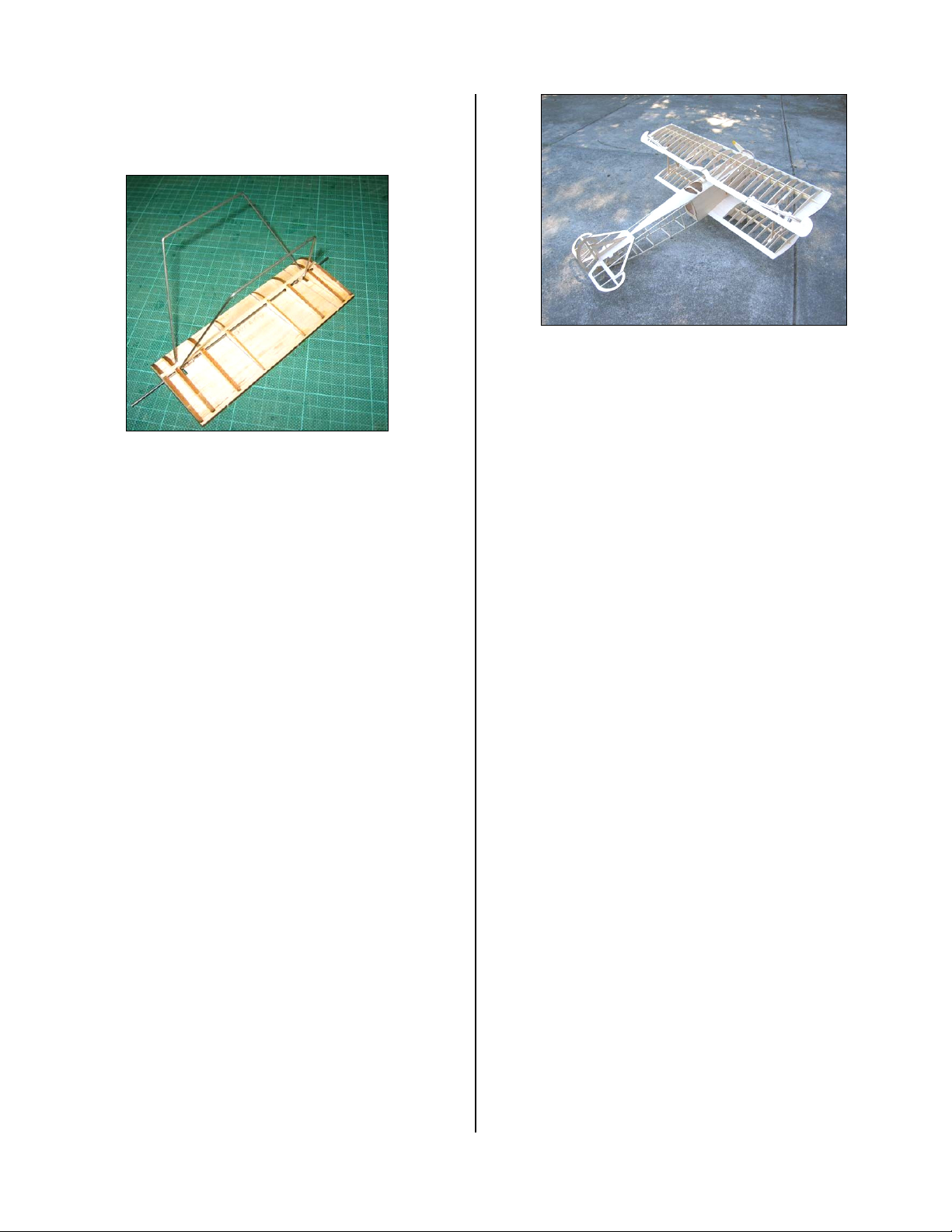
Theundercarriageismadefromthreebitsof1/16”wireto
theshapesshownontheplan.
Withabitofplanningandsomecarefulmeasuring,itis
nottoohardtogetsomesymmetricallybentbitsofwire
readytobesolderedtogether.
Tohelpwiththesoldering,Roddmadeanundercarriage‐
solderingjig.
Bymeasuringfromtheplansthespacingandalignmentof
thevariousbits,theundercarriageisclampedtothejig
andthejointscleanedwiththewirebushontheDremel.
Withthejointsniceandshiny,abitofwirebindsthe
joints.Solderusingplentyofheat.Alternatemethod:lash
thepartstogetherwithKevlarthreadandCAglue.Finish
thejobwithepoxy.
UndercarriageConstructionJig
UndercarriageWingParts
AveryprominentfeatureoftheDVIIwasthe
undercarriagewing.
Theplandesignedthewingtobebuiltoverthewire
undercarriage,sothereareslotsinthebottomoftheribs
toallowtheaxletopassthrough.Thetopslotsarefora
FokkerDVII36”Page10
Copyright©2005‐11M.K.BengtsonAllRightsReservedRev07/11
1/8”squarespar.Thebottomofthewingis1/8”balsa.
Herearethebasicundercarriagewingparts.Alignment
linesfortheribshavebeenmarkedonthebottomplate.
CompletedUndercarriageReadyforSandingandCovering
INSTALLINGTHERADIOCONTROLGEAR
AileronServos
Aileronservosaremountedinwingandattachedwith
shortthreadedrodstotheailerons.Note:Usea“Y”
wiringharnessconnectortowiretheservostoasingle
radioconnection.
BatteryTray
Afteralltheabovehasbeenplaced,mountthebattery
traymadefrom1/8”balsaandusethebatterypositionto
balancethemodelasshownontheplan.
ASSEMBLY
Withthemodelflatonthebench,usethelocatingdowels
toassistwithaligningthebottomwingpanelstothe
fuselageandepoxyinplace.Thecabaneandinterplane
strutsareaddednextfollowedbythetopwing.The
alignmentofthetopwingistobecheckedbutmainlypre‐
determinedbythesestructures.
FittingtheTailSurfaces
Glueonthetailsurfacesnextmakingsurethattheyare
straightandtrue.Thereisaslotinthehorizontalstabilizer
forthetabontheverticalstabilizer.Ifpushrodstyle
controlsareused,cutandbendtherodsfirstwiththe
controlhornsdryfittedinplace.Thenwhentheservosare
centered,gluethehornsinplace.
ModelintheBones
COVERING
Almostanylightweight‐coveringmediumwillbefine,but
avoidanythingthatislikelytowarpthestructure.
Althoughpaintshouldbekepttoaminimuminorderto
saveweight,normalhobbyenamelswilltakewellto
Litespan.
Ifyouintendtoaddextradetailtoyourmodel,bevery
carefulnottooverdothings.Alittledetailcanvery
quicklyaddalotofweight.
Downloadabledecaloutlinesareon‐lineat
http://www.aerodromerc.com/decals.htm
ThemodelshouldROGonpavementorhardsurfaces.On
grass,themodelmayrequirehandlaunching.Becareful
thatyourhandorfingersdonotcatchonthelower
rigging.Launchfirmlyandlevel.Whilethetailsurfaces
aresmall,theyshouldnotneedexcessivethrows.Letthe
modelgainaltitudeslowlyofftherunway.Applyingtoo
muchupelevatoratslowspeedsasksforastall.Make
yourturnsgentlyastightturnsrisktipstallinginany
model.Don’texpecttheelevatortomakethemodelclimb.
Thinkoftheelevatorasadevicetochangetheattitudeof
themodel.Thewingandairspeedultimatelymakethe
modelclimb.Oftendownelevatorappliedatstallingcan
avoidamajorcrash.Themostimportantdetailsfor
properflightoperationsare:
1.CGlocation.Tail‐heavymodelsneverflywellor
atall.
2.Downandrightthrust
3.Straightandnon‐warpedwings.
CONTACTINFORMATION
Distributedby:
BengtsonCompany
WebSite:www.aerdromerc.com
Table of contents
Other Bengtson Toy manuals


Popular Toy manuals by other brands


Torro
Torro Forces of Valor War Thunder 1/24 Series instruction manual

ELEFUN
ELEFUN SMC Sea Fury instruction manual

FB Jets
FB Jets T33 Assembly manual

Viessmann
Viessmann kibri N Windmill with motor functional kit Mounting instruction

Lionel
Lionel Rectifier electric locomotive owner's manual

Mattel
Mattel Barbie CHF54 instructions