Yaesu FTM-6000R User manual

www.arrl.org QST August 2022 39
Reviewed by Rick Palm, K1CE
k1ce@arrl.net
The Yaesu FTM-6000R is a compact, dual-band, one
band at a time, analog (FM) mobile transceiver. The
maximum RF output power is 50 W on both the
2-meter and 70-centimeter bands, but it also
has a signicant extended range on receive,
from 108 MHz to 999.995 MHz (with cellular
blocked; see Table 1). The control head is
detachable and can be connected to the main unit
remotely using the included 10-foot cable.Yaesu also
includes a control head mounting bracket, a radio main
unit mounting bracket, a USB cable, a dc power cable,
and a DTMF microphone (SSM-85D). The radio can
support Bluetooth wireless with the optional BU-4 unit.
There are 1,100 programmable memory channels.
Programmable scanning functions include the VFO
scan, memory scan, and Primary Memory Group
(PMG) scan. A 3 W audio power speaker provides
good, loud audio output. The unit features a Funnel
Air-Convection Conductor (Wind Tunnel) that gathers
cool air from the front and side intakes and directs it to
the radio nal amplier, and out of the unit through the
fan located on the rear panel (see Figure 1).
A new Easy to Operate – III (E2O-III) system imple-
ments a three-tier list that calls up the function settings
in order of the frequency of priority and use. The PMG
allows calling up a group of registered frequencies
regardless of the band. A Memory Auto Grouping
(MAG) calls up memory channels that are automati-
cally categorized in each band for quick and easy
recall.
Basic Operation
The radio turns on by pressing and holding the
POWER/LOCK
switch located in the upper left-hand por-
tion of the controller. Press and hold it again to turn off
the radio. Adjust the volume by rotating the
VOL
knob
just below the
POWER/LOCK
switch. To adjust the
squelch level, push the
SQL/BACK
key in the upper
right-hand corner of the control head, and turn the
Product Review
Bottom Line
The FTM-6000R may look like a basic dual-
band mobile radio, but it’s not. The new
operating features were implemented with
the operators in mind, and that’s where the
technical advancements reside.
Pascal Villeneuve, VA2PV
,
Yaesu FTM-6000R VHF/UHF Mobile
Transceiver
DIAL
knob below it to mute the background noise.
Pushing the
SQL/BACK
key again (or waiting 2 sec-
onds) will return the
SQL
level screen to the normal
operating screen.
To select a frequency band, press the
BAND GRP
key
repeatedly to cycle through ve band choices.
Unwanted frequency bands can be set so they are not
displayed on the rotation of bands.To tune to a specic
frequency, the
DIAL
knob on the right-hand side of the
controller changes the frequency. To change the fre-
quency in 1 MHz steps, press the
DIAL
knob rst, then
rotate it to the desired frequency. To change the fre-
quency in 5 MHz steps, press the
DIAL
knob and hold
down while rotating the knob.You can also press the
numeric keys on the microphone to select a frequency.
For transmission, press the standard microphone
PTT
button. If it is pressed when a non-amateur band is
selected, an alarm sounds,
INHBT
(inhibit) is displayed
on the screen, and transmission is disabled. According

40 August 2022 QST www.arrl.org
Table 1
Yaesu FTM-6000R, serial number 1L020743,
FCC ID# K6620795X40
Manufacturer’s Specifications Measured in ARRL Lab
Frequency coverage: Receive, Receive: 108 – 823.995, 849.1 –
108 – 999.995 MHz (cellular blocked); 868.995, 894.1 – 938.295, 965.2 –
transmit, 144 – 148, 430 – 450 MHz. 983.295 MHz. Transmit: as specied.
Modes: FM, FM-N (FM-Narrow), As specied.
AM (receive only).
Power requirements: Transmit, 10 A at 50 W At 13.8 V dc: Receive, no signal, max.
RF output; receive, 0.5 A at 13.8 V dc. audio and backlights, 510 mA; lights at
(No operating voltage range was specied.) min, 275 mA. Power off, <0.1 mA.
Transmit (hi/med/low):
146 MHz, 7.2/5.2/2.7 A;
440 MHz, 9.5/6.1/2.9 A.
Receiver Receiver Dynamic Testing*
Sensitivity: FM 12 dB SINAD: 137 – FM 12 dB SINAD: 146 MHz, 0.15 µV;
150 MHz, 0.2 µV; 150 – 174 MHz, 0.25 µV; 223 MHz, 0.42 µV; 440 MHz,
174 – 222 MHz, 0.3 µV; 222 – 300 and 0.13 µV; 902 MHz, 0.21 µV.
336 – 420 MHz, 0.25 µV; 420 – 520 MHz, AM: 120 MHz, 0.74 µV.
0.2 µV; 800 – 900 MHz, 0.4 µV; 900 –
999.99 MHz, 0.8 µV. AM: 10 dB S/N,
108 – 137, 300 – 336 MHz, 0.8 µV.
FM two-tone, third-order IMD dynamic 20 kHz offset: 146 MHz, 68 dB,†
range: Not specied. 440 MHz, 67 dB;†10 MHz offset:
146 MHz, 82 dB, 440 MHz, 83 dB.
FM two-tone, second-order IMD dynamic 146 MHz, 89 dB; 440 MHz, 111 dB.†
range: Not specied.
Adjacent-channel rejection: Not specied. 20 kHz offset: 146 MHz, 68 dB;†
440 MHz, 67 dB.†
Squelch sensitivity: Not specied. At threshold: 146 MHz and 440 MHz,
0.11 µV, 0.28 µV (maximum).
S-meter sensitivity: Not specied. For 5 bars: 146 MHz, 1.7 µV; 440 MHz,
1.5 µV.
Audio output power: 3 W into 8 Ωat 2.9 W; THD at 1 VRMS, 3.3%.
10% THD.
Transmitter Transmitter Dynamic Testing
Power output: High/medium/low power, At 13.8 V dc, high/medium/low power:
50/25/5 W. 146 MHz, 49/24/5.1 W;
440 MHz, 55/28/5.5 W.
Spurious signal and harmonic suppression: 146 MHz and 440 MHz, >70 dB.
≥60 dB. Meets FCC requirements.
Transmit-receive turnaround time (PTT Squelch on, S-9 signal: 146 MHz and
release to 50% of full audio output): 440 MHz, 25 – 60 ms.††
Not specied.
Receive-transmit turnaround time (tx delay): 146 MHz and 440 MHz, 43 ms.
Not specied.
Size (height, width, depth): Control head: 1.6 × 5.51 × 1.38 inches, without knob.
Radio body: 1.66 × 5.47 × 5.2 inches, without fan.
Weight 2.43 pounds (radio body, control head, and control cable).
*Test results shown are for standard FM mode. Sensitivity, adjacent channel selectivity,
and dynamic range increased by 1 dB in FM narrow mode.
†Measurement was noise limited at the value indicated. See the Lab Notes on page 43.
††Timing uctuated over this range. The turnaround times are faster than most transceivers,
so this should present no problems in typical use.
KEY:
* Noise limited at value shown.
Measurements in FM mode.
QS2208-PR161
Snd 41
Audio Output (W)
2.9
ChRej
50 90
Adjacent Channel Rejection (dB)
70 cm 67
2 m 68
I3
RX 40 70
Receiver Third-Order Dynamic Range (dB)
(20 kHz offset)
70 cm 67*
2 m 68*
I3
RX 60 90
Receiver Third-Order Dynamic Range (dB)
(10 MHz offset)
70 cm 83
2 m 82
SINAD
0.25 0.1
Receiver Sensitivity (12 dB SINAD, µV)
70 cm 0.13
2 m 0.15
Yaesu FTM-6000R
Key Measurements Summary
to the manual, if transmission is con-
tinued for a long period of time, the
radio overheats and the high tem-
perature protection function is acti-
vated. The power output level is
automatically reduced to the low
power setting. If transmission con-
tinues with the high temperature
protection function engaged, the
radio will forcibly return to the
receive state, a feature that is appre-
ciated when the transmitter remains
engaged without the knowledge of
the operator (which happens occa-
sionally in the eld — for example,
when an operator accidentally

www.arrl.org QST August 2022 41
pushes or sits on the microphone’s
PTT
button). For the
purpose of this review, this feature was not tested.
To lock the keys and
DIAL
knob, press the
POWER/
LOCK
key briey. The word
LOCK
will display on the
screen. The
PTT
button and the
VOL
knob cannot be
locked. Pressing the
POWER/LOCK
button again will
unlock the system, and the word
UNLOCK
will appear
briey on the screen. If you are unaware that the
system is locked, an error message will appear on the
screen when the
PTT
button is pushed. For example,
LOCK
is a reminder that the system is locked and
needs to be unlocked prior to changing frequency.
The E2O-III System for
Assigning Functions and Settings
The E2O-III provides a three-tier system of operating
modes for assigning functions and settings, such as
the CTCSS tone frequency. There are three lists of
functions in order of frequency and priority of use. The
Menu list contains all settings and functions not regis-
tered to the next level (the frequently used Function
list). Thus, the Menu list contains all of the settings that
are of the “set and forget” type, such as the micro-
phone gain setting. To view the Menu list, hold down
the
F/MENU
button while rotating the dial to cycle
through the items.
The Function list contains the settings that are more
frequently used, such as the CTCSS tone frequency,
plus or minus frequency shift for repeater use, and
repeater reverse (which ips the receive frequency to
the transmit frequency, allowing access to the repeater
incoming signal strength and readability on the repeat-
er’s input frequency — information used to set up a
simplex communication off the repeater frequency, for
example).
Figure 1 — The Yaesu
FTM-6000R rear panel.
To register (move) a frequently used function or setting
to the Function list, select the function or item from
the Menu list and then press and hold the
F/MENU
key.
It is then moved to the Function list. To cancel a func-
tion’s registration on the Function list, select it and then
press and hold the
SQL BACK
key; the function is then
moved back to the Menu list. To call up a function in
the Function list, press the
F/MENU
button momentarily,
and then rotate the
DIAL
knob to the desired function/
setting.
Lastly, the
F1
key calls up the one function that is the
highest priority for the individual operator. Examples
include “Home” (the operator’s home repeater) or the
CTCSS tone frequency selection setting (if the oper-
ator travels out of their home area frequently). From
the Function list, select the desired function/setting,
and then press and hold the
F1
key. Then, all you have
to do is push the
F1
key briey to pull up your home
repeater, for example.You can readily change the
assignment of the
F1
key by selecting another function/
setting from the Function list and then pressing and
holding down the
F1
key. Figure 2 shows a diagram
representing the layered structure of the E2O-III
system.
MAG (Memory Auto Grouping)
Memory channels can be grouped and recalled by
band. When you press the
BAND GRP
key while the
radio is in memory mode, the bands switch from air,
VHF, UHF to all memory channels. Then, only the
memory channels in the selected band can be
recalled, for efficient memory channel selection. For
example, I programmed three local repeaters into
memory channels, and an active local aircraft fre-

42 August 2022 QST www.arrl.org
Figure 2 — This diagram represents the layered structure of the E2O-III system. [Graphic courtesy of Yaesu]
quency (118.175 MHz). Pressing the
BAND GRP
key
brought up the air band memory channel. Pressing it
again brought up the VHF band memory channels with
my three local repeater memory channels.
PMG (Primary Memory Group)
Frequently used frequencies and up to ve memory
channels that have been programmed into the PMG
can be displayed for easy selection/operation. For
example, if 25 memory channels are programmed into
the radio, up to ve of them can be registered in the
PMG. I registered three repeater channels in the PMG.
Subsequently, when I pressed the
PMG PW
button, only
those three repeater channels were available to cycle
through and use, adding another aspect to the efficient
operation.
VFO Band Skip
Also adding to the efficient operation, unused bands
can be skipped in the rotation of bands. For example, if
you have no need for monitoring the air band, you can
skip it by selecting the
BND.SEL
(band select) function
in the main Menu list and changing its state to
OFF
.
Other Functions
The frequency and other parameters in a memory
channel can be transferred into the VFO register by
simply pressing and holding the
SQL/BACK
key while
the memory channel is displayed.
Scanning
The radio supports the following scanning functions:
VFO scan, memory channel scan, PMG scan, and
Programmable Memory Scan (PMS). To nd active
frequencies, press the
V/M MW
key to switch to VFO
mode or memory mode, or press the
PMG PW
key for
the PMG mode, and then press and hold the micro-
phone
UP
or
DWN
button to start scanning up or down.
When the VFO scan is active,
VFO.SCN
appears on the
screen.
MEM.SCN
appears during a memory scan, and
PMG.SCN
appears during a PMG scan. Turn the
DIAL
knob and scanning will move up or down in frequency
based on the direction of the knob rotation. When a
busy frequency comes up, the scan pauses, the fre-
quency ashes, and the scan starts again after 3 sec-
onds (other options are discussed below). Press the
PTT
switch or
UP
or
DWN
button to cancel the scanning.
If the scan has paused on a busy frequency, rotate the
DIAL
knob to resume scanning.
PMS (Programmable Memory Scan)
The PMS function scans only the range of frequencies
between the lower and upper limits set by the user
in a pair of PMS programmable memory channels.
Fifty pairs of frequencies (L01/U01 to L50/U50) are
available.
To resume scanning after the scan stops on a busy
frequency, bring up the
SCN.TYP
(scan type) function in
the Menu list. Use the
SCN.RSM
(scan resume) func-
tion to select what happens.
BUSY
means the signal is
received until the signal fades out, and after two sec-
onds, scanning resumes.
HOLD
means scanning stops
and does not resume.
1 SEC / 3 SEC / 5 SEC
means the
signal is received for a specied time, and then scan-
ning resumes. Each memory channel can be selected
to be skipped during a memory scan.

www.arrl.org QST August 2022 43
The Basic Manual
Despite the common tendency of many hams
(including myself) to intuitively operate a radio without
reading the manual, I recommend studying the basic
manual for this radio, as you will learn its wide range of
functioning.A good example of this is the scanning
function. I tried a VFO scan, and the screen display
read
VFO.SCN
. Although it seemed like it wasn’t worki-
ng, it was, and a frequency would not pop up until the
scan came across an active frequency. Traditional
scanning usually involves the rapid increase or
decrease of the actual frequency numbers being
scanned. The manual explains this well.
The basic operating manual is well written and suc-
cinct, and it includes large graphics showing which
buttons to push or dials to rotate. It is in large print,
good for my 70-year-old eyes. The manual is 40 pages,
but that includes all of the ne print that no one ever
reads!
The Advanced Manual
(for Advanced Features)
The supplied basic manual covers more than needed
to get started with this radio. The radio’s advanced
manual (available for download under the product
heading on the Yaesu website) covers more advanced
operations in detail: selecting squelch type, scanning
for the CTCSS frequency, Digital Code Squelch (DCS)
operation, Enhanced Paging and Code Squelch
(EPCS), DTMF operation, Dual Watch feature,
weather broadcast channels and functions, Automatic
Range Transponder System (ARTS), and a complete
explanation of every Menu list function. Additionally, a
10-pin data port on the rear panel allows connection of
a terminal node controller (TNC) for packet operation.
It can also be used to access the Yaesu WIRES-X net-
work as an analog node when connected to an HRI-
200, and this is discussed in the advanced manual.
Conclusion
This is a solid, basic but feature-laden, compact, high-
power, dual-band FM mobile transceiver that is mod-
estly priced. The ultimate litmus test for any product
review is whether or not the reviewer would consider
purchasing the product themselves. In my case, I am
purchasing one for my vehicle.
Manufacturer:Yaesu USA, 6125 Phyllis Dr., Cypress,
CA 90630; www.yaesu.com. Price: FTM-6000R,
$320.
Lab Notes: Yaesu FTM-6000R
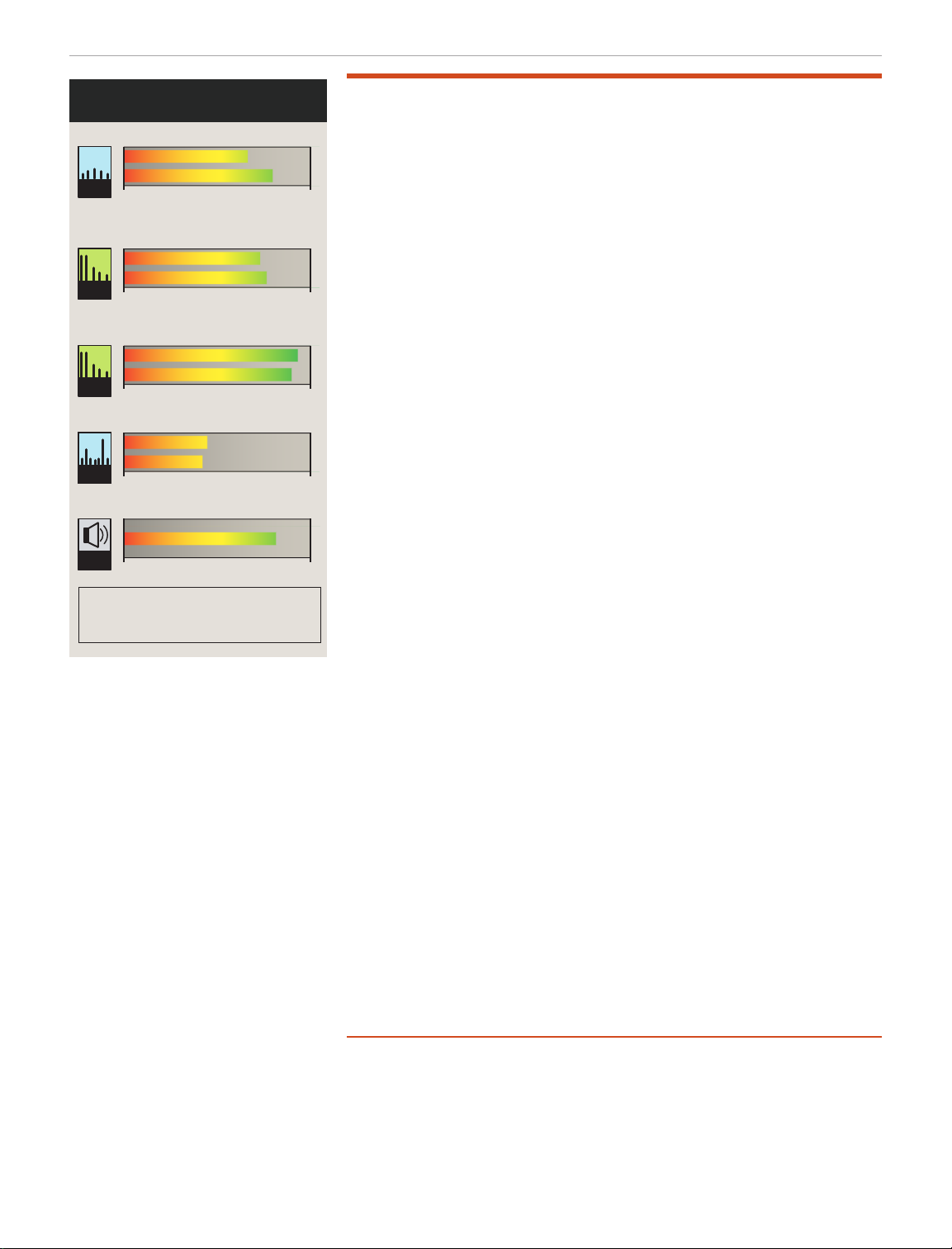
In measuring dynamic range, lab tests put strong
o-channelsignalsintoareceiverinputandlookfor
unwantedresponses.Thedierencebetweenthe
noiseoorofareceiverandthelevelofo-channel
signalsthatcauseunwantedreceiverresponses
isgenerallyknownas“dynamicrange,”typically
expressed in dB. The higher the dynamic range, the
betterthereceiver.Oneunwantedresponsecanbe
intermodulationbetweentwoormoreo-channel
signals, causing a mix of those two signals to appear
inthereceiverpassband.Anotherunwantedeectcan
beforthereceivertolosegain,eectivelydecreasing
itssensitivity.Thedynamicrangeofareceivercan
alsobelimitedbythephasenoiseofthereceiver
internal oscillators. When this noise predominates, the
measurement is reported to be noise limited at the
valueshown.Areceivermeasurementbeing“noise
limited”isnotanydierentfromanyoftheother
eects,soanoise-limiteddynamicrangemeasure-
mentisstillavalidmeasurementofthereceiver’s
dynamicrange.Whatcountsistheactualnumber.A
receiverthatisnoiselimitedat80dBofdynamicrange
isjustasgoodasareceiverthathasgaincompression
measuredat80dB.Infact,ifthedesignofthereceiver
is robust, the gain compression performance could be
sogoodthatalowlevelofphasenoisedominates.
What counts is the dynamic-range number, not the
actual cause of the dynamic-range limit. — Ed Hare,
W1RFI, ARRL Lab Manager
Impressions
Just when you think the ubiquitous dual-band VHF/
UHF FM synthesized transceiver can’t be improved
upon over its 45-year history, along comes the
FTM-6000R. Much of the evolution of these radios
involves improvement of the human operator interface,
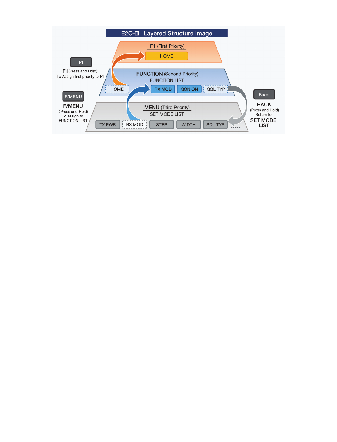
and the FTM-6000R is no exception. I especially like
the E2O-III algorithm for assigning functions and
settings.
There is plenty of audio output from the small speaker,
which res straight up. Audio quality reports from
repeater users have been ne. I’ve never seen a
MUTE
button on any microphone keypad before this one, but
it seems like a convenience when needing to quiet the
radio instantly. The microphone ts comfortably in the
hand. I like that if I were to accidentally sit on the micro-
phone and cause transmission, the radio’s protocol is
to force the receiver.

44 August 2022 QST www.arrl.org
Radio Analog PTRX-9700 SDR Adapter
Add-On
Bottom Line
The PTRX-9700 is a high-quality add-on for the
IC-9700 that provides an easy way to integrate
an external SDR receiver, opening the possi-
bility to demodulate 90 kHz of a band simulta-
neously or monitor two in-band frequencies at
once, using your choice of SDR software.
Reviewed by Rus Healy, K2UA
k2ua@arrl.net
Like its HF sibling (the IC-7300) has done on 160 –
6 meters, Icom’s IC-9700 has taken the VHF/UHF
world by storm. The IC-9700 covers the 144 – 148, 430
– 450, and 1240 – 1300 MHz amateur radio bands. It
also shares the form factor, intuitive front panel layout,
multifunction display, and many other features that
make the IC-7300 so popular. The IC-9700 has quickly
become the go-to radio for many serious VHF/UHF
operators, including those who operate the most
demanding modes, such as EME.
In early 2020, I found a great deal on a new IC-9700.
This radio quickly replaced the high-performance
transverters I had been using for all three bands for
several years. It’s seen service in VHF contests, por-
table operations such as the microwave sprints, day-
to-day MSK144 meteor scatter activity on 2 meters,
and JT65 and Q65 EME operations on 144, 432, and
1296 MHz. It’s a radio that does many things quite
well, and despite its small size, relatively spartan front-
panel control layout, and limited rear-panel control
capabilities, it has drawn in many demanding
operators.
Turbocharging the IC-9700 Receiver
Radio Analog rst developed enhanced SDR function-
ality for the IC-7300 and followed that up with the
PTRX-9700 for the IC-9700. Fundamentally, the
PTRX-9700 allows for the connection of an external
SDR to the IC-9700. Installing this product is a simple,
nonintrusive, and easily reversible change to the radio.
The PTRX-9700 uses the existing 10 MHz reference
input (SMA) connector on the radio’s rear panel, along
with a splitter provided with the kit, to allow that con-
nector to be used for its original function and the SDR
output.You attach an SDR of your choosing to the
IC-9700 to reap the benets of SDR receiver operation
in parallel with the IC-9700’s own receiver.
Why might you want to add an SDR to the IC-9700,
which already offers panadapter functionality? For one
thing, you can use it to monitor two frequencies and/or
modes on the same band at the same time. For
another, you can monitor and/or control the IC-9700
from your preferred SDR software and hardware of
your choosing. Or you can use an external SDR to
independently drive a larger display, which allows you
to monitor a large segment of a band. And you can use
it to do things the IC-9700 can’t do natively.
For example, an EME operator may use the PTRX-
9700, feeding another SDR along with HDSDR soft-
ware and MAP65 software (provided with WSJT-X) to
decode 90 kHz — the entire EME band segment — at
once, something the IC-9700’s own receiver cannot
do. Another application for two receivers might be to
operate two instances of WSJT-X on one band at the
same time, with one running MSK144 and the other on
Q65. Or you might run CW or SSB on the IC-9700 and
decode meteor scatter signals using MSK144 on the
SDR. Or perhaps monitor the beacon subband while
making contacts in the weak-signal portion of the
band, or during an FM contact.
Architecture
The PTRX-9700 is a small module that mounts to
existing screw locations on the IC-9700 main board. It
sits inline with the three receive signal paths, one per
band, providing buffering, ltering, and multiplexing.

www.arrl.org QST August 2022 45
QS2208-ProdRev02
IC-9700
PTRX-9700
Amplifier
Blocks
RADIOANALOG
Power
Regulation
Combining
Filtering
Multiplexing
VHF
UHF
23 cm
IF/RF out
REF In
REF out
13.8 Vdc
Figure 3 —FunctionalblockdiagramofthePTRX-9700.
Figure 4 —PTRX-9700installedintheIC-9700.RFconnections
onthenearsideoftheboardarecompleted.TheIC-9700’s
internalcablesnowroutetothePTRX-9700,andthePTRXboard
routesconnectionsbacktotheradio’smainRFboardafterltering
andbuering.
Functionally, it breaks out each band’s receive RF
signal and feeds the signals from the IC-9700’s cur-
rently selected band to the internal receiver and to an
external SDR that you provide, with no loss in signal
such as you’d have with a receive splitter. The board’s
architecture is shown in Figure 3.
One important caveat: The PTRX-9700 can operate
only on the currently selected band of the IC-9700.
If you’re operating, say, 144 MHz, it feeds only the
144 MHz signal out to the external SDR. It doesn’t offer
the ability to use the external SDR to watch a second
band while using the IC-9700’s built-in waterfall display
on the currently selected band.
Installation
Installing the PTRX-9700 took me about 20 minutes.
The biggest part of the job is removing and then rein-
stalling all of the bottom cover screws on the radio — it
has a dozen of them. Once you have the bottom cover
off the radio, there’s plenty of room to work, and
installing the board is straightforward. The key steps are:
1) Disconnect power from the radio, and remove the
bottom cover.
2) Remove two of the screws that hold the main board
to the radio, and replace them with standoffs and
longer screws, mounting the PTRX-9700 to the
standoffs.
3) Disconnect the three receive signal cables (one per
band), and connect the PTRX-9700 board in series
with them using the provided cables.
4) Insert the PTRX-9700 into the external reference
signal path with the provided cable.
5) Insert the PTRX-9700 into the power path to the
main board by moving a power connector and
inserting the provided wiring harness.
The most intrusive part of the installation is cutting a
few plastic wire ties to facilitate moving the last section
of the radio’s power wiring harness to the PTRX-9700.
Figure 4 shows the PTRX-9700 installed in the
IC-9700. At this stage, the RF connections on the
PTRX-9700 input are completed, and the cables sup-
plied with the PTRX-9700 route RF back to the radio’s
main RF board. Figure 5 shows the board after the
installation is completed.
Radio Analog makes installation easy by providing an
l-shaped tool with properly placed tabs for removing
and installing the tiny U.FL RF connectors that Icom
uses to attach cables to the board. These are difficult
to manipulate and securely attach without this tool —
props to Radio Analog for including it.
Once I had installed the board, buttoning up the radio
and testing it were all that remained. For level of dif-
culty, I’d give this a 1 out of 5.Very straightforward.
Options
If you are using the IC-9700 without an external refer-
ence, then all you need to do after the installation is
connect your external SDR with the provided SMA
male-to-male cable. If you plan to use an external ref-
erence with the radio, you have a couple of options:
Use the provided splitter board to inject the reference
signal, or upgrade the radio’s external reference func-
tionality using a Leo Bodnar Reference Injection Board
(see the next review in this issue of QST) and accom-
panying 49.152 MHz reference oscillator.
The Reference Injection Board ts inside the radio side
by side with the PTRX-9700 and uses the provided
cable and splitter. Radio Analog provides a connection
diagram for this option on their website. Both options t
into the radio easily, and the interconnections are no
more challenging than either one by itself.

46 August 2022 QST www.arrl.org
Operation
Once you’ve installed the PTRX-9700 and, if appro-
priate, connected the external reference to the pro-
vided splitter board, connect your SDR and select
appropriate SDR software for your computer. With my
setup, I use HDSDR. I did initial testing with a HackRF
One and then moved to an Airspy HF+. Since the
Airspy HF+ also works well with MAP65 for 144 MHz
EME, that’s the SDR on which I settled. I’ve also tested
with a FUNcube Dongle Pro+, which is another good
choice.
To use the PTRX-9700, you’ll need an SDR that
covers your bands of interest, such as 144 – 148 and
430 – 450 MHz. For 1240 – 1300 MHz operation, the
IC-9700 uses 311 – 371 MHz as its IF range, so
1296 MHz is equivalent to 367 MHz at the rear-panel
SMA connector, where the SDR connects. Based on
that, to cover the entire 144 – 1300 MHz range of the
IC-9700, you’d need an SDR that covers 144 – 148,
311 – 371, and 430 – 450 MHz. Even a simple SDR
like an RTL-SDR dongle can do the job, but you’ll be
rewarded with better performance if you choose a
higher-performance SDR.
For EME operators, MAP65 (which is part of the
WSJT-X installation) is a great way to go with the
PTRX-9700. MAP65 supports multiple SDR options,
including the FUNcube Dongle, SDR-IQ, Perseus,
IQ+, WSE, SoftRock, and others. The key to covering
the full EME band is being able to sample at 96000
or 95238 Hz.
Manufacturer: Radio Analog, www.radioanalog.com.
Price: $329.
For digital mode operation on 1296 MHz, especially for
EME, I like option 2.You can add the PTRX-9700
before or after you install the Leo Bodnar kit, if you go
that route. It doesn’t add any time to the installation
process, so I recommend doing both at the same time.
Figure 5 shows the two options installed inside the
IC-9700.
Figure 5 —AddingtheLeoBodnarexternalreferenceboardtothe
IC-9700alongsidethePTRX-9700.Thetwooptionsseemalmost
madetogotogether.TheBodnarboardisvisiblejusttotheright
ofthecentersupportpostandconnectstothePTRX-9700usinga
cableprovidedwiththePTRX-9700.
Reviewed by Rus Healy, K2UA
k2ua@arrl.net
When it was released, the Icom IC-9700 received criti-
cism, especially in the digital communications commu-
nity, for its frequency accuracy and stability. Icom
released a rmware update (version 1.10) that made it
easier to set the radio’s internal oscillator to match an
external 10 MHz reference. Both topics were discussed
in the Product Review of the IC-9700 in the January
2020 issue of QST. That adjustment is a manually
Leo Bodnar IC-9700 Reference Injection Board
and Mini Precision GPS Reference Clock
applied setting, not a dynamic tracking feature that
those familiar with the use of GPS-disciplined oscilla-
tors (GPSDOs) might expect.
Some good news for enthusiasts of optimal frequency
accuracy and stability comes from UK-based Leo
Bodnar Electronics, who introduced a nonintrusive,
fully reversible, and affordable method of adding an
external reference with tracking to the IC-9700. The
Reference Injection Board is a small PC board that
installs easily inside the IC-9700 and connects to an

www.arrl.org QST August 2022 47
nect the 49.152 MHz reference that you’ll see a differ-
ence in operation.
The board is held in place with two screws and two
spacers. The screws are longer than the factory ones
to accommodate positioning the board above a per-
forated shield, where the injection board couples
49.152 MHz energy into the radio.
Leo Bodnar’s attention to detail is evident in the
board’s design. The factory screws thread into two
holes in the board for permanent storage. Should you
ever decide to remove the Reference Injection Board,
you can remove those screws from it, remove the
board, and place the screws back into the main board
— a nice touch.
Setup and Operation
You don’t need any test equipment to align and use the
Reference Injection Board with the miniGPS receiver.
You’ll need to congure the miniGPS to supply the cor-
rect reference frequency, using the conguration soft-
ware available from the Leo Bodnar product page. It’s
available for Windows or Mac OS X (see Table 2).
Connect the miniGPS to a USB port using the sup-
plied mini USB cable, and the supplied GPS antenna
to the SMA GPS port. Then open the software and
you should see a display similar to the one shown in
Figure 6. If you’re using the Mac application, the view
is different but includes the same information, plus
additional graphical elements, including a satellite
map of the current GPS position.
Set the frequency to 49152000, and then click the
update button in the right-hand pane. This saves the
Bottom Line
The Leo Bodnar miniGPS and Reference Injec-
tion Board provide a simple, aordable method
of locking your IC-9700 to a GPS referenced
clock for improved frequency stability and
accuracy. High stability really matters, espe-
cially for digital mode operating, and this setup
provides it in a small, well-designed package.
Figure 6 —The32mAoutputsettingisrecommendedbyLeo
BodnarfordrivingtheIC-9700ReferenceInjectionBoard.The
utility(availablefromtheminiGPSproductpageforMacand
Windows) requires only setting the output frequency, as shown.
external reference oscillator running at 49.152 MHz.
See the gures in the PTRX-9700 review in this
issue for more details on the board’s location and
connections.
49.152 MHz is not exactly a common reference fre-
quency. That said, TCXO and OCXO modules are
available that can provide this frequency, but GPS-
disciplined options are also readily available. Leo
Bodnar offers GPSDOs that are programmable to
work at nearly any frequency between 400 Hz and
810 MHz, including the Mini Precision GPS Reference
Clock (miniGPS, as labeled), reviewed here. Paired
with the Reference Injection Board, the miniGPS pro-
vides a great solution for GPS-locking the IC-9700,
and one that works seamlessly with the Radio Analog
PTRX-9700 that’s also reviewed in this issue of QST.
Installation
The Reference Injection Board installs easily inside the
radio. The process is simple; the most time-consuming
part is taking the bottom cover off the radio. Follow
these installation steps:
1) Remove all connections from the radio. Remove the
bottom cover.
2) Peel off the black spongy cover on the reference
input shield. Leo Bodnar recommends affixing it
elsewhere inside the radio, but I removed it from my
radio.
3) Remove the screws on the main board that are
marked 10 and 11. Install them in the two blank
holes on the Reference Injection Board.
4) Install the Reference Injection Board using the sup-
plied hardware.
5) Install the supplied SMA extension cable between
the injection board and the rear panel 10 MHz refer-
ence input. Alternatively, connect it using a supplied
cable with the PTRX-9700 board.
6) Reinstall the bottom cover.
Reconnect and test the radio. Its operation should be
unaffected by installing the board. It’s not until you con-

48 August 2022 QST www.arrl.org
Table 2 — miniGPS Specifications
Manufacturer Specifications
Input power: 5 V, 250 mA.
Output signal: Square wave, congurable for
6.4, 9, 9.9, or 10.3 dBm
(approximately 4 – 10 mW).
SMA connector.
Output frequency: 400 Hz – 810 MHz, congurable through
Mac or Windows software.
GPS antenna: SMA connector, supports active or
passive GPS antennas. Active antenna
with magnetic base and 3-meter cable
included with the miniGPS.
Phase noise: Figure 7 shows the phase noise graph
provided by Leo Bodnar.
conguration. Make sure that the output is set to
32 mA (about +10 dBm), as shown in Figure 6.
Connect the miniGPS output to the IC-9700 reference
input SMA connector, and use the checkbox in the
upper right-hand corner of the software window to
enable the output.Your IC-9700 is now GPS-locked. If
you’re tuned into a signal, you’ll be able to toggle the
miniGPS output on and off and hear any difference in
the radio in its reference-locked and unlocked states.
Leo Bodnar provides the easy-to-follow process for
adjusting the radio’s internal reference oscillator to
match the miniGPS on the product page.
What’s remarkable about Figure 6 is that I took this
screenshot while using the miniGPS in my ham shack,
which is in the basement. The GPS antenna, supplied
with the miniGPS, was sitting next to the GPS receiver
at the time. I wasn’t expecting to receive any GPS sat-
ellites — let alone acquire a position x — until taking
the antenna outdoors. Ultimately, as many as 10 GPS
satellites were part of the x. It took only a few minutes
of powered-up time to reach a GPS x, even though
this was the rst time the unit had been powered up
since before it shipped from England. I was impressed.
Other Applications
I use a second miniGPS with my portable, tripod-
mounted station for 10 and 24 GHz. In that setting, the
miniGPS is congured for a 10 MHz output. It drives
both transverters (Down East Microwave for 10 GHz,
DB6NT for 24 GHz).
A signicant advantage of the miniGPS is that it locks
quickly. From a cold start, it achieves lock in about
1 second, even after sitting for weeks at a time. Fast
Figure 7 —Phasenoiseat10MHzoutput.[Graphiccourtesyof
LeoBodnar]
lock time is important because time spent waiting for
the GPS receiver to lock is time lost from making
QSOs. By contrast, my previous 10 MHz OCXO solu-
tion took about 20 minutes for the oven to stabilize,
and it consumed a lot more power. The miniGPS
runs from a USB adapter and adds only about 85
mA of current drain at 14 V. By comparison, the
OCXO drew more than 800 mA until the oven stabi-
lized, and then dropped back to about 250 mA. Cur-
rent drain is an important consideration for portable
work, and the Leo Bodnar miniGPS is a denite win
in that category. Its fast lock time is another important
benet.
In addition to the miniGPS, Leo Bodnar Electronics
also offers a larger model with the same output fre-
quency range, and two BNC output connectors, for
165 GBP (around $200 USD). They also offer a
number of other interesting products, some of which
are available in the US at https://v3.airspy.us/.
The Leo Bodnar miniGPS and Reference Injection
Board make great additions to your IC-9700. The
improvement in frequency accuracy and stability —
with such a small, affordable setup — makes a
worthwhile improvement to the IC-9700’s function-
ality, and one that is especially important to digital
mode operators on the 432 and 1296 MHz bands.
The miniGPS has many applications thanks to its
exible frequency and power-level settings. Both
have long-term homes in my ham shack.
Manufacturer: Leo Bodnar Electronics,
www.leobodnar.
com. Available in the US via
https://v3.airspy.us. Price: MiniGPS, $160;
IC-9700 Reference Injection Board, $49.95.

www.arrl.org QST August 2022 49
Reviewed by Michael Fluegemann, KE8AQW
ke8aqw@arrl.net
For anyone looking for a low-prole mobile or station
antenna for 2 meters and 70 centimeters, the 2M/440+
made by COMPACtenna may be right for you. I had
the pleasure of using the 2M/440+ antenna for more
than several weeks and found it to work well. At only
9 inches tall, it is ideal for cars that park in garages
with low clearances. COMPACtenna also sells the
CompacCounterpoise, which turns this antenna into a
great base-station antenna with the benet of being
small, perfect for those who need to conceal their
antennas from view.
Hardware Details
The 2M/440+ antenna looks like a black cylindrical
tube that is about 9 inches tall and 1.5 inches wide. It
has an NMO connector with a leaf spring as the center
connector. The manufacturer specications say the
antenna can handle 100 W on the 2-meter band and
75 W on the 70-centimeter band, with an SWR of less
than 2:1 on both bands (see Table 3). My SWR tests
show that the antenna performed as specied or
better. With the mag mount on my vehicle, I got an
average of 1.8:1, and the station installation with the
ground plane was even better, with an average of 1.5:1.
Unlike other antennas that are shortened with a
loading coil, this antenna has a patented design “with
a special design construct of spiraled and cylindrical
metal sheeting.” Even though this antenna seems
small, it is advertised with 5 dB-MEG gain. The geom-
etry of the antenna provides the matching network,
and because the antenna has a strong magnetic near
eld, local noise is reduced.
I used this antenna with a Larsen NMO magnetic
mount on my Ford Focus and with the CompacCoun-
terpoise at my house. The counterpoise kit came with a
bracket that has an NMO connector for the antenna
and an SO-239 connector for the coax. There are four
ground-plane elements that are 18 inches long. After
COMPACtenna 2M/440+
Bottom Line
At only 9 inches tall, the COMPACtenna is
an ideal low-profile, dual-band antenna for
cars that need low clearances or for a stealth
station installation without compromising on
performance.
Table 3 — COMPACtenna 2M/440+
Manufacturer’s Specifications
Frequency Coverage: 144 – 148 MHz, 430 – 450 MHz
(V)SWR: Nominal <2:1, 144 – 148 MHz; 430 – 450 MHz
Maximum Power Rating: 100 W for the 2-meter band;
75 W for the 70-centimeter band
Connector: NMO
Gain: Nominal 5(+) dB-MEG
Antenna Type: Unique Electric/Magnetic Field Diversity Science &
Technology Patented Design (Patent No. US 9,407,001)
Maximum Duty Cycle at Maximum Power Rating: 1 minute in any
2-minute period
Dimension: Length, 9 inches × 1.5 inches diameter
attaching them with the provided screws, washers, and
nuts, I was able to attach the mount to my deck with the
provided hose clamps (see Figure 8). The kit also came
with lube for the threads, as well as a rubber gasket.
Road Trip
Shortly after receiving the 2M/440+ antenna, I took a
road trip from Detroit, Michigan to Huntsville, Alabama

50 August 2022 QST www.arrl.org
to visit my friends for their wedding. This was the per-
fect opportunity to test the antenna. I connected it to
my Kenwood TM-V7A and positioned the antenna on
the roof of my Ford Focus in the rear passenger corner
(see Figure 9), as the instructions suggested better
omnidirectional performance on a corner. Throughout
my 10-hour trip, I tried hitting several 2-meter and
70-centimeter repeaters. I found I was able to hit sev-
eral of them. Specically, while I was near Nashville, I
was able to hit NE4MA at 442.800 MHz with a good
signal from 21 miles away. Then on my trip home, I
was able to hit WC8OH at 145.110 MHz with a good
signal from over 25 miles away, and I could still hear it
faintly at 40 miles away.
Figure 8 —TheCOMPACtenna2M/440+balconystation
installationwithCompacCounterpoisegroundplane.
Figure 9 —TheCOMPACtenna2M/440+vehicleinstallationwith
theLarsenNMOmagneticmount.
Satellites
Satellite operation was one of the other use cases
suggested in the instructions. While using the radio in
my car, I tried a couple of FM satellite passes with the
new ISS repeater and SO-50. On both occasions I was
able to get into the satellites and make a couple of
contacts.This could be a good option for those without
a handheld Yagi or those who would prefer a simple
setup that does not require moving an antenna.
Base Station
With the antenna mounted on the CompacCounter-
poise on my deck and plugged into my Kenwood
TM-V7A, I was able to hit several of my local repeaters
with ease. I have not had a base-station antenna for
VHF/UHF and have relied on a Diamond NR22L dual-
band 5/8-wave vehicle-mounted antenna in the past to
call into nets on repeaters that were too hard to hit with
a handheld. The performance of the COMPACtenna
2M/440+ installed at low height was comparable to the
performance of my Diamond antenna mounted on the
vehicle.
Final Thoughts
The COMPACtenna 2M/440+ antenna performed well
for its small footprint. I highly suggest this antenna for
anyone who needs the short form factor but doesn’t
want to compromise on the performance.
Manufacturer: COMPACtenna, www.compactenna.
com. COMPACtenna 2M/440+ Antenna, price:
$109.95. COMPACtenna CompacCounterpoise NMO
Mount Base Station Ground Plane, price: $99.95.
Larsen NMOMMRPL Mobile Antenna Magnet NMO
Mount, price: $69.99.
Other manuals for FTM-6000R
2
Table of contents
Other Yaesu Transceiver manuals

Yaesu
Yaesu FT-8900R User manual

Yaesu
Yaesu VX-150 User manual

Yaesu
Yaesu FTM-350AR User manual

Yaesu
Yaesu FTM-500DR User manual

Yaesu
Yaesu FTDX101MP Manual

Yaesu
Yaesu FTM-7250DR User manual

Yaesu
Yaesu Mark-V FT-1000MP User manual

Yaesu
Yaesu FTM-500DR User manual

Yaesu
Yaesu FT-65R/E User manual

Yaesu
Yaesu FT-80C - SERVICE User manual

Yaesu
Yaesu VX-150 User manual

Yaesu
Yaesu FT-950 Technical manual

Yaesu
Yaesu FTM-200DR User manual

Yaesu
Yaesu FT-77 User manual

Yaesu
Yaesu FT-101ZD User manual

Yaesu
Yaesu CPU-2500R User manual

Yaesu
Yaesu FT-23R MKII User manual

Yaesu
Yaesu FT2DR User manual

Yaesu
Yaesu FTM-7250DE User manual

Yaesu
Yaesu FTM-3200DE User manual