TABLE
OF
CONTENTS
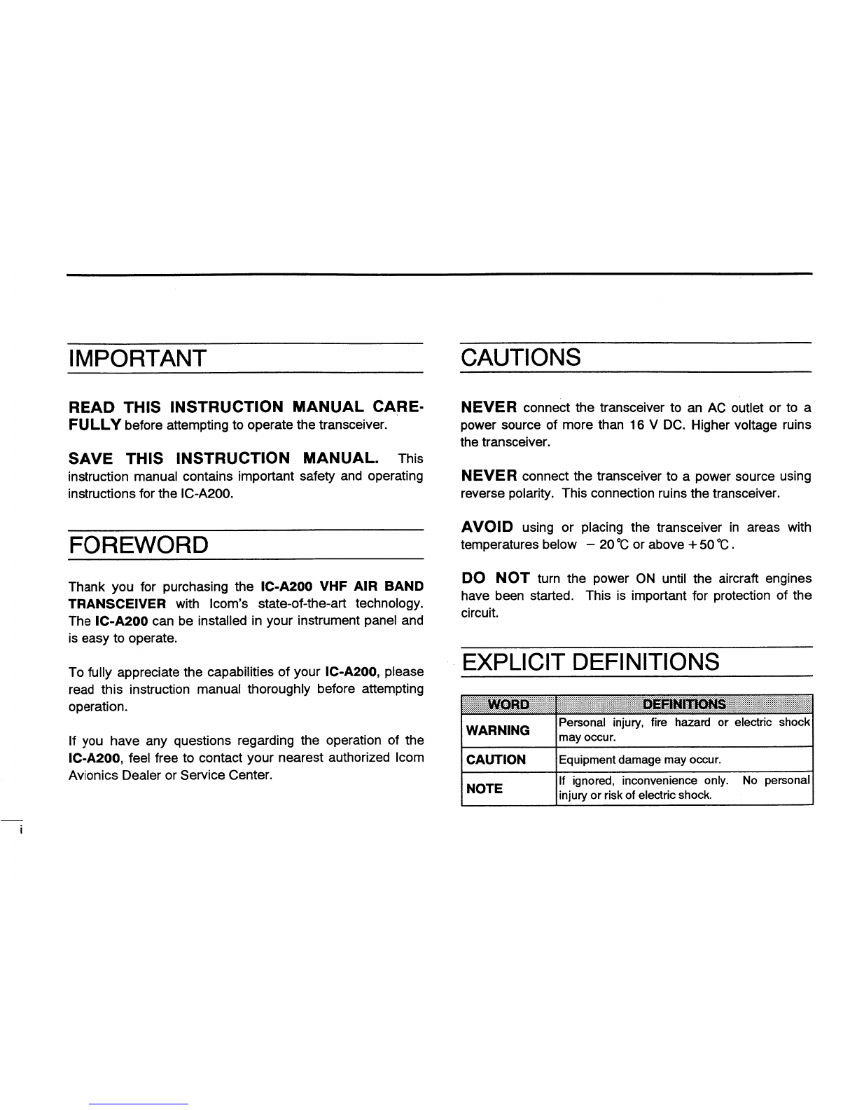
IMPORTANT
................................................................
..i
3.
RECEIVING
AND
TRANSMITTING
...................
..6
I
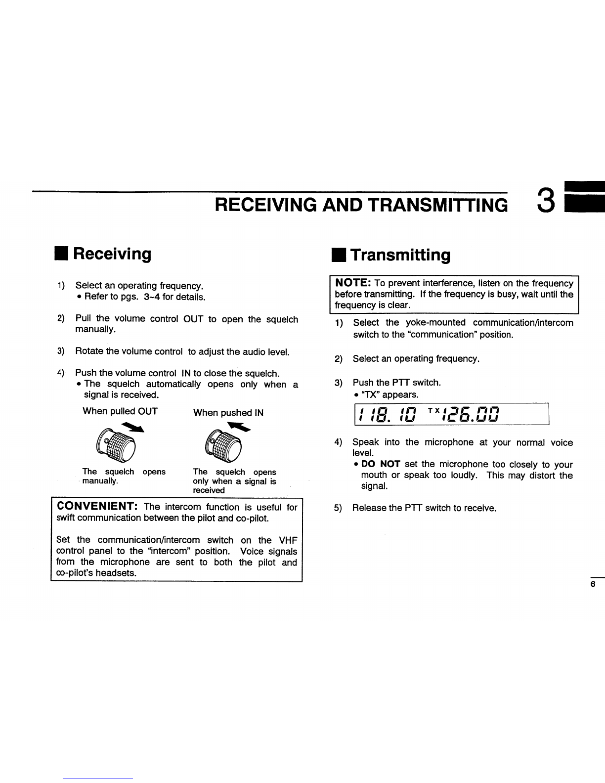
Receiving
....................................
..
FOREWORD
.................................................................
..i
I
Transmitting
................................
..
..6
..6
CAUTIONS
...........................................................
..i
4.
MEMORY
OPERATION
......................................
..7~10
EXPLICIT
DEFINITIONS
..............................................
..l
I
Programming
a
memory
channel
.......
..
I
Programming
example
.............................................
..
TABLE
OF
CONTENTS
..............................................
..ii
I
Memory
recall
in
the
STBY
window
..........................
..
I
Memory
recall
in
the
USE
window
............................
..
I
Memory
recall
example
...........................................
..
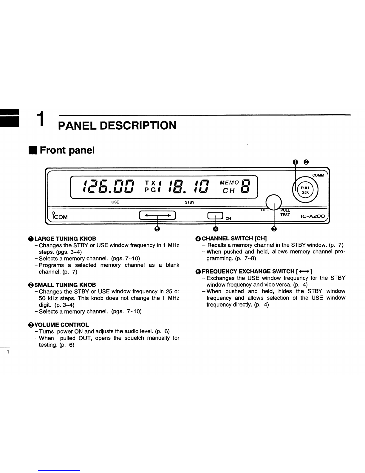
1.
PANEL
DESCRIPTION
................
..
-I
a-n
I
Front
panel
................................................................
..
I
Function
display
...............................
..
I
Remote
switches
and
jacks
..............
..
2.
FREQUENCY
SELECTION
............
..
I
Frequency
selection
methods
..........
..
I
STBY
window
frequency
selection.....
I
Frequency
exchanging
.....................
..
I
USE
window
frequency
selection
.....
..
I
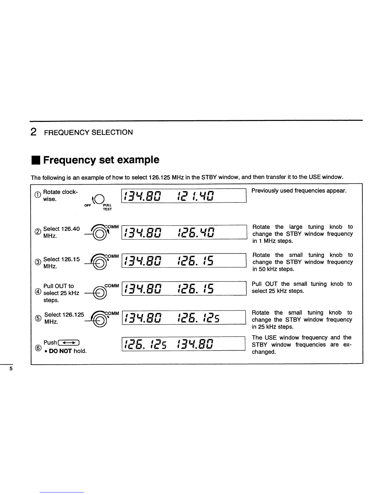
Frequency
set
example
....................
..
bi
-
- - - -
-
-
-
- - - -
-
v
-
-
- -
- -
-
-
- -
--
- - -
-
----
- - -
-
- -
- - - -
- -
- -
- -
--
In
- -
-
- - - - - - -
-
-
- -
---
-
- - - -
-
-
--
-
- -
-
- - - -
-
-
-
-
-
---------
-
-
--
-
. .
.
-
---
-
- - -
-
-
-
-
-
---
-
-
-
-
--
-
- -
-
- - - -
-
-------
-
---
-
-
-
-
--
-
-
.
.
.
- -
-
- - - -
-
- -
-
----
-
-
-
-
--
I\)I\J—‘N
U1-h-500030‘!
I
Programming
notes
....................
..
I
Remote
memory
selection
.......
..
5.
REMOVAL
AND
INSTALLATION
..........................
..
I
Transceiver
removal
..............................................
..
I
Transceiver
installation
...........................................
..
6.
SPECIFICATIONS
......................
..
I
General
........................................
..
I
Transmitter
................................
..
I
Receiver
................................................................
..
-
-
-
-
- -
-
-
-
- -
-
- - -
---
-----
¢
-
-
- -
--
- -
-
-
---
- -
-
-
-
-
-
-
-
- -
- -
--
-
-
-
-
-
- - -
-
- -
1
-
- - - - - - - -
-
- - -
--
-
o
-
o
- - -
-
-
I
-
-
-
u
c
n
-
-
u
- - - -
n
- -
--
- -
-
-
-
-
-
-
- -
-
---
-
- - - - -
--
---
-
-
-
- -
- -
-
- -
-
- - - -
-
- -
-
---
--
..7
—*'-~:
:
::
OQ(O(O@\l
11
11
11
12
12
12
12