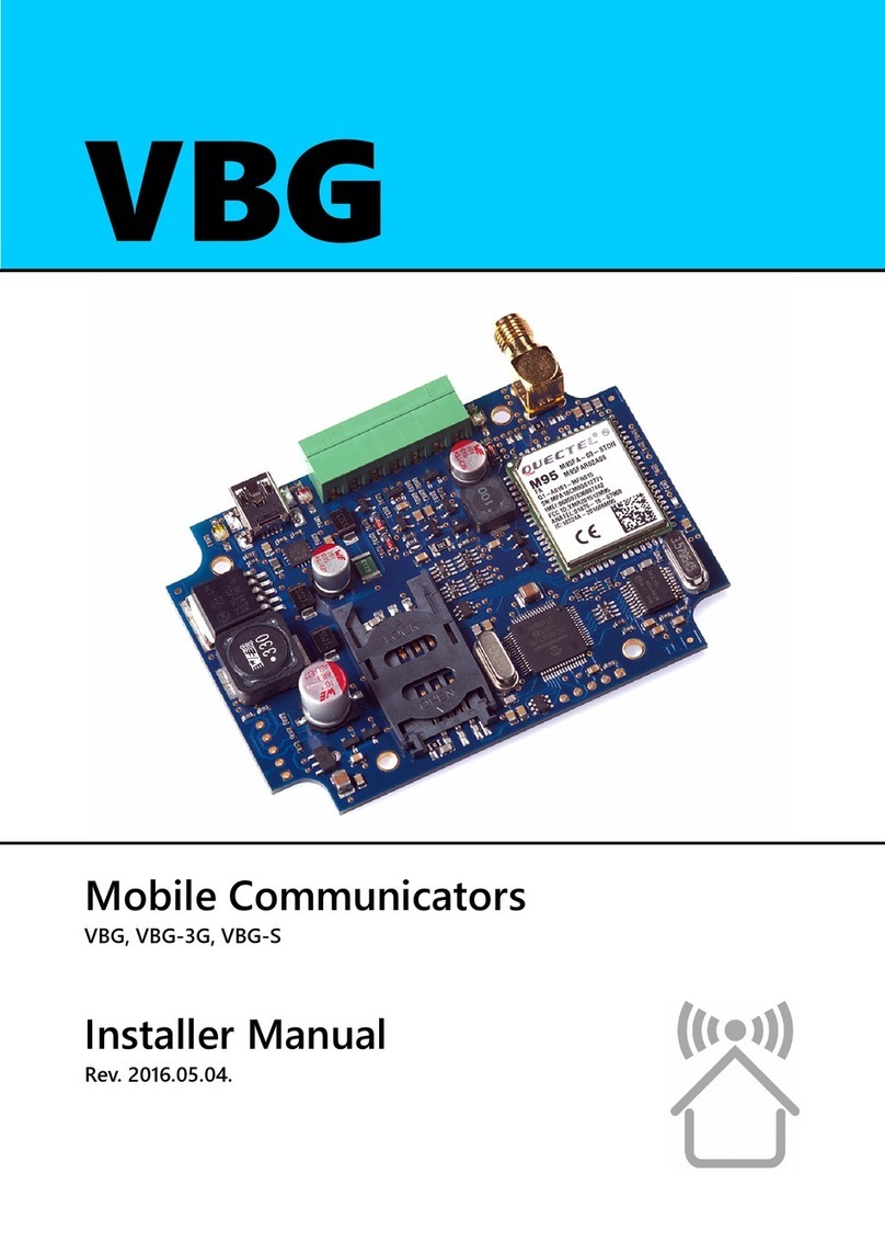
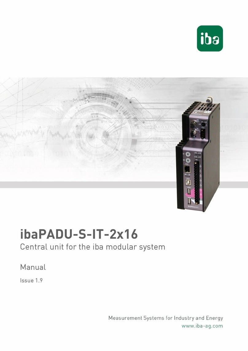
BENSHAW BIPC-300200-01 User manual

Benshaw retains the right to change specications and illustrations in text without prior notication.
The contents of this document may not be copied without the explicit permission of Benshaw.
©2020 Benshaw, Inc
710-22291-00A
Control option
for EMX4e/EMX4i soft starters
Installation Guide
3-wire control board

Disclaimer 3-Wire Control Board
Contents
1Disclaimer .......................................................................................................................... 2
2Warnings............................................................................................................................ 2
3Product Overview.............................................................................................................. 3
4Setup Procedure Overview ............................................................................................... 4
5Installation ......................................................................................................................... 5
6Specifications .................................................................................................................... 7
1 Disclaimer
The examples and diagrams in this manual are included solely for illustrative purposes. The
information contained in this manual is subject to change at any time and without prior
notice. In no event will responsibility or liability be accepted for direct, indirect or
consequential damages resulting from the use or application of this equipment.
2 Warnings
WARNING
Isolate the soft starter from mains and control voltage before connecting or
removing the board.
2 Instructions

3-Wire Control Board Product Overview
3 Product Overview
3.1 Description
The 3-wire control board simplifies the connection of external pushbuttons to EMX4 soft
starters.
3.2 Options
Select the correct 3-wire control board according to the application’s control voltage:
•BIPC-300200-01 .................... 120 VAC
•BIPC-300200-02 .................... 24 VDC
3.3 Design schematic
K1
231
L N
K1
K1
N/O
N/C
C
22292.A
1
Trip
2
Stop
3
Start
Instructions 3

Setup Procedure Overview 3-Wire Control Board
4 Setup Procedure Overview
WARNING
Isolate the soft starter from mains and control voltage before connecting or
removing the board.
WARNING
Connect the 3-wire control board to control voltage from the same fuse or circuit
breaker as the soft starter control voltage.
1. Mount the board on the soft starter panel.
2. Connect TB2 and TB3 on the control board to the external controls.
•TB2: stop pushbutton
•TB3: start pushbutton
3. Connect TB1 and TB5 on the control board to the soft starter control terminals.
•TB1: Relay output A (41, 42, 44)
•TB5: Reset (10,11) and Start/stop (11, 12)
4. Connect TB4 on the control board to control voltage.
5. Apply control voltage to the soft starter and control board.
6. Set soft starter parameter 8A Relay A Function to “Trip”.
4 Instructions

3-Wire Control Board Installation
5 Installation
5.1 Physical installation
88.9 (3.5)
63.5 (2.5)
54.0
(2.125)
79.4 (3.125) 4.8
(0.19)
Ø 4.5
(0.18)
4.8
(0.19)
4.8
(0.19)
4.8
(0.19)
22296.A
Screw the board to the soft starter panel or use the DIN rail clips supplied with the board.
5.2 Connections
External controls
3-wire control board
Soft starter
TB4
TB1
TB5
TB3
TB2
1
1
1
1
1
2
2
3
2
2
2
12
11
42
41
44
K1
K1
10 6
5
22293.A
L(+)
1
4
3
2
1
External controls: start pushbutton (normally open)
2
External controls: stop pushbutton (normally closed)
3
Control voltage
4
Soft starter: Relay output A (set = Trip)
5
Soft starter: Start/stop input
6
Soft starter: Reset input
Instructions 5

Installation 3-Wire Control Board
5.3 Preventing immediate restart after a trip is reset
WARNING
The EMX4 start input shares a contact with the reset input. The
motor could restart
unexpectedly when a trip on the soft starter is reset.
Reset via soft starter digital input
If the application uses the soft starter reset input, the external reset pushbutton must be
connected to two normally closed contact blocks:
•Connect one contact block to the soft starter reset input (10, 11)
•Connect one contact block independently to the control board
2
1
LK1
5
N
K1
K1
N/O
N/C
C
4
3
22294.A
1
Trip
2
External controls: reset pushbutton (normally closed)
3
Soft starter: Reset input
4
External controls: stop pushbutton (normally closed)
5
External controls: start pushbutton (normally open)
6 Instructions

3-Wire Control Board Specifications
Reset via external pushbutton
If an external Reset pushbutton is installed, connect the pushbutton to the soft starter reset
input and the external stop pushbutton.
External controls
3-wire control board
Soft starter
TB4
TB1
TB5
TB3
TB2
1
1
1
1
1
2
2
3
2
2
2
12
11
42
41
44
K1
K1
10
5
4
L(+)
1
2
7
6
22295.A
3
1
External controls: start pushbutton (normally open)
2
External controls: stop pushbutton (normally closed)
3
External controls: reset pushbutton (normally closed)
4
Control voltage
5
Soft starter: Relay output A (set = Trip)
6
Soft starter: Start/stop input
7
Soft starter: Reset input
6 Specifications
•Connections
Terminal type (control board) ...................................... screwless spring cage connectors
Terminal type (soft starter) ......................................................... unpluggable connectors
Maximum cable size ........................................................................... 2.5 mm2 (14 AWG)
•Certification
CE ............................................................................................................. EN 60947-4-2
RoHS ................................................................ Compliant with EU Directive 2011/65/EU
UL ...................................................................................................... UL508 Recognized
Instructions 7

BENSHAW
615 Alpha Drive
Pisburgh, PA 15238
Phone: (412) 968-0100
Fax: (412) 968-5415
BENSHAW Canada
550 Bright Street
Listowel, Ontario N4W 3W3
Phone: (519) 291-5112
Fax: (519) 291-2595
È710-22291-00A*ËÍ
710-22291-00A
This manual suits for next models
1
Table of contents
