Bentel ALISON/8L User manual

ITALIANO
INSTALLAZIONE (FIG. 1)
Per l’installazione di questa Tastiera procedere
come descritto di seguito (vedere Figura 1)
1. Aprire lo sportello 14.
2. Svitare le viti 15.
3. Togliere il coperchio 16.
4. Togliere la Scheda Elettronica 11 dal fondo 12.
5. Se previsto, installare il Deviatore Antistrappo 2
come mostrato nel dettaglio ingrandito di Figura 1.
Il Deviatore Antistrappo è opzionale (art. ASNC).
Il Deviatore Antistrappo deve essere in-
stallato per ottenere la certificazione
IMQ-SISTEMI DI SICUREZZA al II LIvello
di Prestazione.
6. Passare il cavo per i collegamenti attraverso
l’apertura 13.
7. Fissare il Fondo 12 alla parete o alla scatola
predisposta tramite le opportune asole.
8. Se è stato installato il Deviatore Antistrappo 2,
fissare il Tassello Antistrappo 1.
ATTENZIONE - Il Deviatore Antistrappo è ineffica-
ce se la Tastiera viene fissata ad una scatola.
9. RiagganciarelaSchedaElettronica11 alFondo 12.
10. Se installato, collegare il cavetto del Deviatore
Antistrappo 2al connettore 5.
11. Impostare il LIVELLO BPI come descritto nel
paragrafo omonimo.
12. Impostare l’INDIRIZZO come descritto nel pa-
ragrafo “Codifica dei Dispositivi”.
13. Eseguire i COLLEGAMENTI sulla morsettiera
10 (vedi fig. 2).
14. Riagganciare il Coperchio 16 al Fondo 12.
15. Avvitare le viti 15.
COLLEGAMENTI (FIG. 2)
TALISON/8L è utilizzabile nelle centrali Omnia4-
8 e Kyo4-8-32.
LIVELLO BPI (FIG.2)
Il Livello BPI della Tastiera deve essere uguale a quello
della centrale alla quale sarà collegata (leggere le istru-
zioni della centrale per conoscere il suo Livello BPI).
IlLivelloBPIdellaTastierasiimpostatramiteiponticelli3
e 9come mostrato nella Tabella di Figura 2.
®
MADE
IN
ITALY
ALISON/8L
Tastiera di Controllo a LED
LED Control Keypad
ENGLISH
INSTALLATION (FIG. 1)
Work carefully through the following steps (see
Figure 1).
1. Open the flip 14.
2. Remove the screws 15.
3. Remove the frontplate 16.
4. Detach the PCB 11 from the backplate 12.
5. Insert the Snatch Switch 2as per Figure 1 (for
keypads with Snatch Switches only).
The Snatch Switch is an accessory item (order
code ASNC).
Keypads which are not fitted with Snatch
microswitches, DO NOT COMPLY with
IMQ-SECURITY SYSTEM Performance
level II certification.
6. Pull the connection wires through the wire entry
13.
7. Using wall anchors, secure the backplate 12 to
the wall or onto an outlet box.
8. Secure the Snatch bracket 1to the wall (for
keypads with Snatch Switches only).
The Snatch Switch cannot be used when mount-
ing the ALISON/8L on an outlet box.
9. Reattach the PCB 11 to the backplate 12.
10. Connect the Snatch switch 2to the connector
5(for keypads with Snatch Switches).
11. Set the BPI Level, as described under
‘SETTINGUPTHEBPILEVEL’.
12. Assign the Address, as described under
‘ASSIGNINGTHEADDRESS’.
13. Complete the Connections on the terminal
board 10, refer to ‘CONNECTIONS’.
14. Replace the Frontplate 16.
15. Using the screws 15 secure the Frontplate.
CONNECTIONS (FIG. 2)
TALISON/8L is compatible with Omnia4-8 and
Kyo4-8-32 Control panels.
SETTING UP THE BPI LEVEL (FIG. 2)
The BPI Level of the keypad must match the BPI
Level of the Control panel (refer to your Control
panel manual for details).
Using jumpers 3and 9, as per Table in Figure 2,
select the keypad BPI Level.

CODIFICA DEI DISPOSITIVI
Per impostare l’indirizzo sulla tastiera ALISON/8L,
si proceda nel modo seguente:
Nella procedura sotto descritta si tenga presente che
in ogni momento il reinserimento del ponticello 9o
la richiusura del microswitch antisabotaggio deter-
minano l’uscita dalla fase di programmazione ed il
ritorno alla normale operatività della tastiera. Per
impostazione predefinita (di fabbrica) alla prima
accensione la tastiera è indirizzata con il valore ‘01’.
ATTENZIONE: se il volume del Buzzer è stato
impostato come “MUTO” la tastiera non emetterà
alcun suono (vedi Regolazione volume Buzzer).
1. Togliere il coperchio affinchè la tastiera risulti in
sabotaggio;
2. Collegare la tastiera al BUS BPI (se non ancora
collegata);
3. Togliere il ponticello 9;
4. Fase di attesa di 5 secondi con ponticello 9 tolto, e
microswitch antisabotaggio aperto (coperchio tolto);
5. La tastiera emetterà un Beep ad indicare l’ingresso
nella fase di codifica dei dispositivi;
6. Si accenderanno i 4 LEDs contrassegnati con il n. 6
(Fig.2)ad indicareche siènella fasedi codificadell’indi-
rizzo della tastiera.
7. Gli 8 LEDs contrassegnati con il n. 4(Fig.2) simu-
leranno un Dipswitch virtuale: in sintesi ogni coppia
di LEDs degli 8 indicati in figura 2 simula un
microinterruttore; il primo LED/microinterruttore da
impostareinizierà alampeggiare. InFig. 2un esem-
pio di corrispondenza tra i LEDs e microinterruttori.
8. Agendo sui tasti CC
CC
Ce DD
DD
Dper spostarsi verti-
calmente e i tasti AA
AA
Ae BB
BB
Bper spostarsi orizzontal-
mente si imposta l’indirizzo voluto.
9. Premere quindi Enter E: per rendere effettivo l’in-
dirizzo impostato. Si avrà un Beep di conferma.
10. Si torna al punto 4.
Terminata la fase di programmazione accertarsi
di aver reinserito il ponticello 9e di aver corret-
tamente richiuso il coperchio della tastiera.
Dallafasediprogrammazionedell’indirizzo,premendo
il tasto esi torna al punto 4. Gli indirizzi assegnati
devonoesserediversi per tuttiidispositividellostesso
tipo; questo significa che possono coesistere
nell’impianto tastiere ed inseritori con lo stesso
indirizzo poiché l’Unità Centrale è in grado di
riconoscere il tipo di Dispositivo (vedi Tab. 1).
REGOLAZIONE VOLUME DEL BUZZER
Il Volume del Buzzer può essere regolato su tre
livelli: nullo (buzzer muto), basso e alto. Il volume
del Buzzer si regola tramite il tasto e: tenere
ASSIGNING THE ADDRESS (FIG. 2)
NOTE: if the buzzer is set to “MUTE” the keypad
will be silent at all times (see below
“ADJUSTING the Buzzer VOLUME”).
1.Remove the frontplate to generate Tamper.
2. Connect the keypad to the Control panel BPI
BUS (terminals +, C, R, -).
3. Remove the jumper [9]:
Tafter several seconds the keypad will emit an
audible signal and the 4 LEDs on the left (see 6
in Figure 2) will turn ON;
Tthe four pairs (up/down) of LEDs (see 4in Fi-
gure 2) will simulate 4 DIP switches;
Tone of the first pair of LEDs will blink to indicate
access to the Keypad Addressing phase.
On first power up the Keypad will assume the
preset (at default) Address ‘01’.
4. Assign an Address to the Keypad (refer to the
example in Figure 2).
TUse Aor Bto select the LED/DIP switch.
TUse Cor Drespectively, to turn the RED
LED ON or OFF as required, in accordance
with the following logic:
RED LED ON = DIP switch ON
GREEN LED ON = DIPswitch OFF
TIf you wish to cancel and restart, press e.
NOTE: Devices of the same type (e.g. 2
Keypads) must have different Addresses.
However, different devices (e.g. a Keypad
and Reader) may share the same
Address.
5. Press Eto confirm the selected Address. The
Keypad will emit an audible signal and step back.
6.Reinsert the Jumper [9], in accordance with
the BPI Level (refer to “Setting up the BPI
Level”), then replace the frontplate.
NOTE: The Keypad will exit the
progamming phase when you insert the
Jumper and/or replace the frontplate.
ADJUSTING THE BUZZER VOLUME
Using the ee
ee
ekey select the required volume:
OFF (Mute), High or Low.
Each level is identified by a specific audible signal:
Tshort low beep = Volume Off (Mute)
Tlong low beep = Low Volume
Tlong high beep = High Volume
premuto il tasto efino a quando non si ottiene il
volume desiderato. I tre livelli possibili sono se-
gnalati da beep di intensità e lunghezza diversa:
Tbeep corto e basso = Volume nullo (buzzer muto);
Tbeep lungo e basso = Volume basso;
Tbeep lungo e alto = Volume alto.
DESCRIZIONE SPIE
Per la descrizione delle spie e tasti presenti sul-
la tastiera si rimanda ai manuali di installazione
delle centrali collegate alla tastiera stessa.
$
8
1
15
13
23
5
7
9
12 11
16
15
14
10
4
6
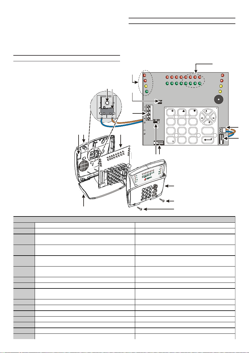
Fig. 1 - Parti - Parts
PARTI - PARTS
1Tassello Antistrappo Snatch Bracket
2Deviatore Antistrappo (opzionale) Snatch Switch (Accessory item)
3P o ntice llo p e r im p o stare il Live llo
BPI(vedi Fig. 2) BPILevel Jumper
(S e e Fig ure 2)
4LEDs per impostare l'indirizzo(vedi
Fig. 2) Address LEDs
(S e e Fig ure 2)
5Connettore per il Deviatore
Antistrappo Snatch Switch Connector
6LEDs che si accendono in fase di
impostazione indirizzo (vedi Fig. 2) Address LEDs
(S e e Fig ure 2)
7Deviatore Antisabotaggio Tamper Switch
8Deviatore Antisabotaggio Tamper Switch
9P o ntice llo p e r im p o stare il Live llo
BPI(vedi Fig. 2 BPILevel Jumper
(S e e Fig ure 2)
10 Morsettiera per i collegamenti Terminal board
11 Scheda Elettronica PCB
12 Fondo Backplate
13 A p e rtura p e r cavi W ire e ntry
14 S p o rte llo Flip
15 Viti di chiusura Screws
16 Coperchio Frontplate
BENTELSECURITYs.r.l.si riservaildirittodimodificarele
specifichetecnichediquestoprodottosenzapreavviso.
LED DESCRIPTIONS
Refer to the Control panel INSTALLATION
Manual for the full description of the Keypad
LEDs and Keys.
BENTELSECURITYs.r.l.reservestherighttochange
thetechnicalspecificationsofthisproductwithoutpriornotice.

Fig. 2 - Setup e Collegamenti - Setup and Connections
$
LIVELLO BPI
BPI LEVEL
NIVEAU BPI
Ponticello 3
Jumper 3
Pontet 3
LIVELLO BPI
BPI LEVEL
NIVEAU BPI
Ponticello 9
Jumper 9
Pontet 9
6
+
R
C
-
L1
OUT
+F
+
R
C
-
$/,621/
MORSETTIERA- TERMINAL BOARD
+
C
R
-
Morsetti per il collegamento del BUS
Dati con la Centrale Terminals for the connection between the BPI BUS and Control panel
CARATTERISTICHE - TECHNICAL SPECIFICATIONS
Tensione Voltage 10.5 V ÷ 14 V
±5 %
Temperatura di funzioamento Operating Temperature +5 ÷ +40° C
Livello di Prestazione Performance Level II
Corrente assorbita a riposo Stand By Current 40 mA
Corrente Massima Maximum Current draw 90 mA
ISTISBL3ALSL8 0.3 101005P7.0
BENTEL SECURITY s.r.l. - Zona Ind. S. Scolastica - 64013 CORROPOLI - TE - ITALY
Tel.: +39 0861 839060 - Fax: +39 0861 839065
E-mail: info@bentelsecurity.com - http://www.bentelsecurity.com
TAB. 1- L'indirizzo viene assegnato secondo la
posizione dei LED/microinterruttori. Nella tabella a
lato sono mostrate le 8 combinazioni possibili.
The ON/Off status of the LED/DIP
microswitches will determine the Keypad Address.
The table on the left, shows 8 Address
combinations.
Microinterruttore
Microswitch
N.
Indirizzi/Address
1 2 3 4 5 6 7 8
1 off off off off off off off of
f
2 off off off off ON ON ON ON
3offoffON ON off off ON ON
4off ON off ON off ON off ON
Other Bentel Keypad manuals


