The JA-80E hard-wired keypad 2 / 2 MHE51203
The JA-80E hard-wired keypad
The JA-80E is a component of Jablotron’s OASiS alarm system and is
designed to control and program the system. It has a built-in proximity access
card reader and allows the wiring up of a separate door detector. The keypad
should be wired to the control panel.
Installation
Installation shall only be undertaken by technicians holding a certificate
issued by an authorized distributor. The keypad is for indoor installation only,
typically by a main entrance door.
1. Open the keypad housing (by pressing the tab on the bottom) and
disconnect the inter-housing connection cable inside (by pulling the
connector from the board).
2. Install the rear housing to the desired location.
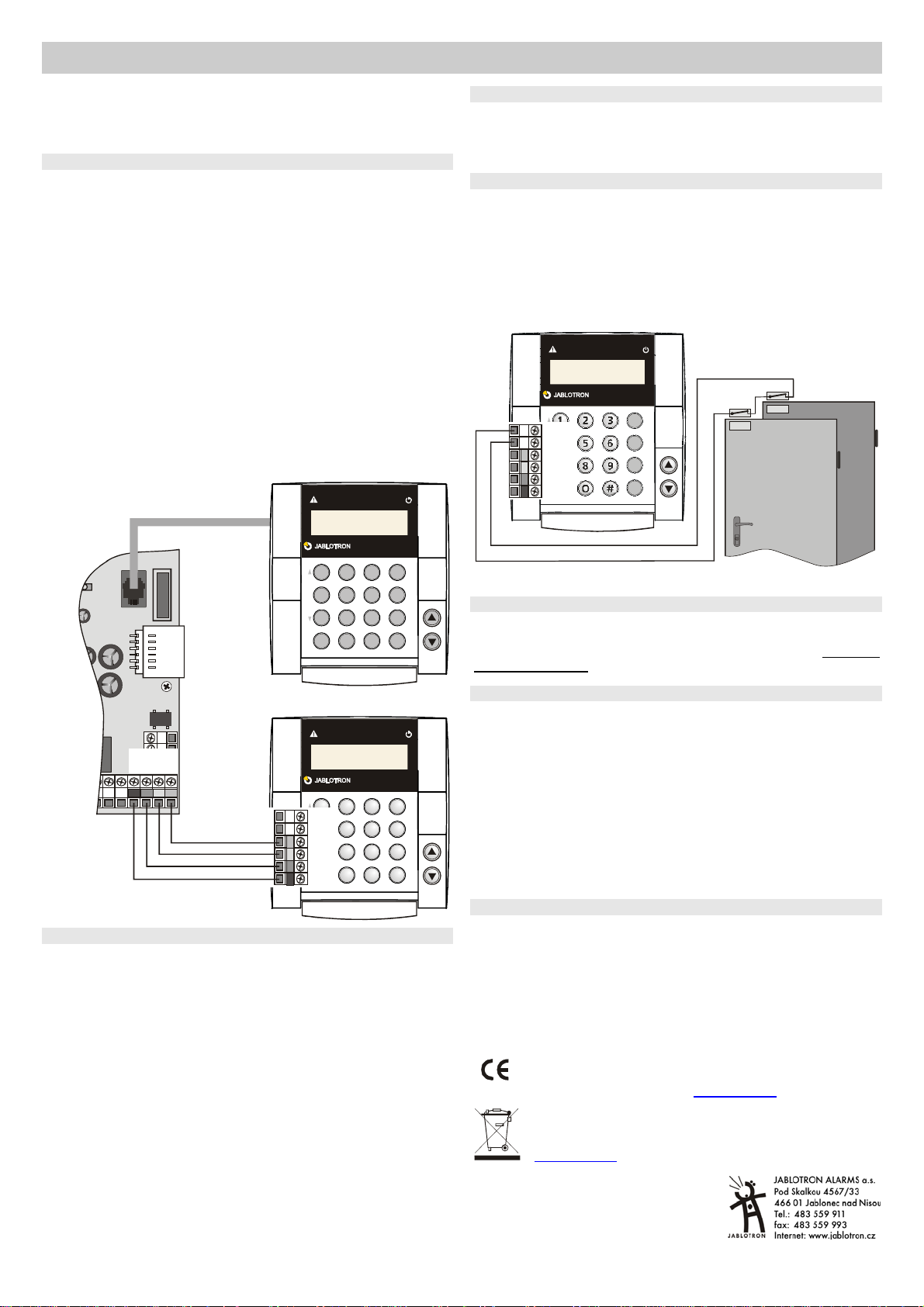
3. Connect the control panel bus cable. There are two possibilities:
o Use a twisted-pair cable (max. 100m) for keypad installation. The
correspondingly marked terminals in the keypad unit and in the control
panel should be connected together (GND, A, B, +U).
o Use a flat four-cord telephone cable with RJ connectors (max. 10
metres) for temporary (test) installation. There is a digital bus connector
in the control panel, and in the keypad too. The keypad’s digital bus
connector is supplied in the package and must be wired to the circuit
board (remove a blind flange from the rear plastic and route the wires
through the hole).
4. Install the external door detector (if required) and connect its cable to
the IN and GND terminals.
5. Connect the inter-housing cable to the keypad board. Attach the keypad
to the rear housing.
6. Keypad operating instructions are found in the control panel manual.
OASIS 80
A B C
BC
?
B
A
IN
GND
+U
B
A
GND
GND
A
B
+U
digital bus
cable
OASIS 80
A B C
BC
?
B
A
Keypad menu – language selection and door bell function
If the ∗ key is kept pressed while is being powered-up the internal keypad
menu will be displayed allowing the selection of the desired language. Using
the arrows choose your language and confirm selection by the ∗ key.
In this menu the door bell function can also be enabled or disabled (if
enabled the keypad makes a sound when its IN input is triggered).
To exit the menu, press # (exiting also occurs after 10 seconds’ inactivity).
Notes:
• The keypad power can be switched on by connecting the bus cable or by
switching on the control panel power.
• Each keypad has its own menu, i.e. each keypad in the system can have
its own unique settings.
• The keypad keeps its settings even if its power is disconnected (settings
can only be altered via the keypad menu).
Three minute time-out of displaying the alarm status
To comply with EN standards the keypad does not indicate the status of the
alarm system while the system is set (armed). Indication only returns when the
keypad is operated or an entrance delay is triggered. It is however possible to
program permanent indication via the control panel, if considered appropriate.
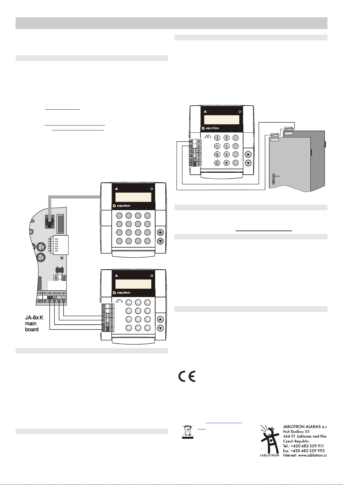
Installing a door detector
It is possible to wire up a detector(s) to the keypad via the IN input. The IN
input terminal is triggered when disconnected from GND. The control panel’s
natural reaction to the IN input being triggered is a delayed intruder alarm
(unchangeable reaction).
Notes:
• If the IN input is not used, connect it to GND.
• The IN input only reports to the control panel at the moment of being
triggered (a so-called pulse reaction, which means that the keypad
cannot signal permanently open doors). The input belongs to the C
section (can not be changed) and if there is more than one JA-80E in
the system their inputs IN are not distinguished by the system.
OASIS 80
A B C
ABC
?
B
A
IN
GND
+U
B
A
GND
An example of door detector wiring
Disabling the tamper sensor
To disable the tamper sensor, short out the jumper in the keypad unit close
to the tamper sensor (equipped with a spring). This is useful when carrying the
keypad unit around with a long cable while servicing the system. During
normal system use this jumper must remain open circuited
Keypad text editing
There are two kinds of text: device and code names (displayed on the
second line after the address number), and other system text.
The names can be edited via the keypad after pressing and holding the ? key
in service mode – see the control panel installation manual. The edited text is
only stored in the keypad unit used for editing.
If you use a PC running OLink software to set the texts, you will set the texts
in all connected keypads.
If you add a new keypad to the system, you can transfer (synchronize) all the
latest texts to the keypad by using OLink to read the texts from the control
panel. (OLink reading the control panel texts triggers the keypad into listening
in to the bus and copying the texts into itself).
The texts can only be copied into the keypad but cannot be read out of it.
Technical specifications
Power via the control panel bus
Standby consumption 30mA
RFID cards Jablotron PC-01 or PC-02 (EM UNIQUE 125kHz)
Length of digital bus cable max. 100m
Door detector input IN = normally closed loop
Dimensions 113 x 121 x 63 mm
Environment according to EN 50131-1 II. internal
Operating temperature range -10 to +40 °C
EN 50131-1 and CLC/TS 50131-3 classification class 2
FCC ID VL6JA80E
Jablotron Ltd. hereby declares that the JA-80E is in compliance
with the essential requirements and other relevant provisions o
Directive 1999/5/EC and complies with part 15 of the FCC rules.
Operation is subject to the following two conditions: 1. This device
may not cause harmful interference, and 2. This device must
accept any interference received, including interference that may
cause undesired operation.
CAUTION: Changes or modifications not expressly approved by
Jablotron could void the user´s authority to operate the equipment.
The original of the conformity assessment can be found on the web
site www.jablotron.com, Technical Support section.
Note: Although this product
does not contain any harmful
materials we suggest you return
the product to the dealer or
directly to the manufacturer
after use.