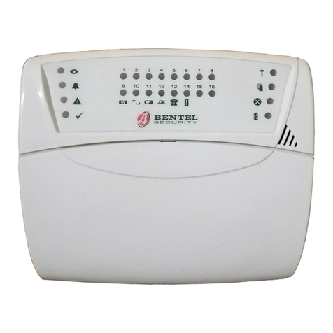
Bentel OmniaTAST-R User manual

®
PROGRAMMING FROM KEYPAD
Omnia/S
DAT n. U0805

This Control panel can be programmed through the OMNIA 3.0 software or higher.
Hereby, Bentel Security,
declares that the above mentioned Omnia/S is in compliance with the essential requirements and
other relevant provisions of Directive 1999/5/EC1999/5/EC.
The complete R&TTE Declaration of Conformity for each Panel can be found
at www.bentelsecurity.com/dc.htmlwww.bentelsecurity.com/dc.html.
This control panel complies with CEI 79-2 2a Ed.1993CEI 79-2 2a Ed.1993.
Installation of these systems must be carried out strictly in accordance with the instructions de-
scribed in this manual, and in compliance with the local laws and bylaws in force.
The above mentioned Omnia/S has been designed and made to the highest standards of quality and per-
formance.
The manufacturer recommends that the installed system should be completely tested at least once a
month.
BENTEL SECURITY srl shall not be responsible for damage arising from improper installation or main-
tenance by unauthorized personnel.
BENTEL SECURITY srl reserves the right to change the technical specifications of this product with-
out prior notice.

CONTENTS
KEYPAD OPERATIONS 5
General rules for the INSTALLER MENU . . . . . . . . . . 5
Installer menu . . . . . . . . . . . . . . . . . . . . . . . . 6
View buffer . . . . . . . . . . . . . . . . . . . . . . . . . . 7
Zones status . . . . . . . . . . . . . . . . . . . . . . . . . 7
Outs managements . . . . . . . . . . . . . . . . . . . . . 8
Cancel call queue . . . . . . . . . . . . . . . . . . . . . . 8
Voice functions . . . . . . . . . . . . . . . . . . . . . . . . 8
Telephone-number Programming . . . . . . . . . . . . . . 10
Description Programming (labels) . . . . . . . . . . . . . 10
Installer code . . . . . . . . . . . . . . . . . . . . . . . . . 11
User codes . . . . . . . . . . . . . . . . . . . . . . . . . . 11
Digital Keys and Cards . . . . . . . . . . . . . . . . . . . 13
Enable/Disable Digital Keys/Cards . . . . . . . . . . . . . . 15
Parameter programming . . . . . . . . . . . . . . . . . . . 16
Firmware release . . . . . . . . . . . . . . . . . . . . . . . 16
PARAMETER PROGRAMMING 17
General rules for programming from Keypad . . . . . . . 17
Readers in Configuration . . . . . . . . . . . . . . . . . . 19
Keypads in Configuration . . . . . . . . . . . . . . . . . . 19
Input expanders in Configuration . . . . . . . . . . . . . . 19
Output expanders . . . . . . . . . . . . . . . . . . . . . . 19
Power stations . . . . . . . . . . . . . . . . . . . . . . . . 19
Enable Keypad Partition (Areas) . . . . . . . . . . . . . . 20
Enable Reader Partitions (Areas) and Masks . . . . . . . 20
Zone Parameters . . . . . . . . . . . . . . . . . . . . . . . 20
Zone Type . . . . . . . . . . . . . . . . . . . . . . . . . . . 21
Zone Attributes . . . . . . . . . . . . . . . . . . . . . . . . 22
Zone Alarm Cycles . . . . . . . . . . . . . . . . . . . . . . 22
Zone Partitions (Areas) . . . . . . . . . . . . . . . . . . . 22
Zone status Voice messages . . . . . . . . . . . . . . . . 23
Off time . . . . . . . . . . . . . . . . . . . . . . . . . . . . 23
Output Type . . . . . . . . . . . . . . . . . . . . . . . . . . 23
Reserved (for manual commands) . . . . . . . . . . . . . 23
Programming Main Unit Outputs (Block no. 17) . . . . . . 24
Programming Expander no. 1 Outputs . . . . . . . . . . . 24
Programming Expander no. 2 Outputs . . . . . . . . . . 25
Programming Expander no. 3 Outputs . . . . . . . . . . 25
Programming Expander no. 4 Outputs . . . . . . . . . . 25
Programming Expander no. 5 Outputs . . . . . . . . . . 25
Programming Expander no. 6 Outputs . . . . . . . . . . 25
Programming Expander no. 7 Outputs . . . . . . . . . . 25
Programming Expander no. 8 Outputs . . . . . . . . . . 25
Partition (Area) Entry time . . . . . . . . . . . . . . . . . 25
Exit time . . . . . . . . . . . . . . . . . . . . . . . . . . . 26
Last exit time . . . . . . . . . . . . . . . . . . . . . . . . . 26
Primary and Subordinate Partitions (Areas): Depends on . 26
Jump other answering devices . . . . . . . . . . . . . . . 26
Rings . . . . . . . . . . . . . . . . . . . . . . . . . . . . . 27
Disable Line Tone Check/Dialling mode . . . . . . . . . . 27
Answerphone message . . . . . . . . . . . . . . . . . . . 27
Digital Communicator Call Attempts . . . . . . . . . . . . 27
Number to dial, Customer code and Protocol . . . . . . . 28
Definition of Digital Communicator Actions 1 though 32 . . 28
Definition of Digital Communicator Actions 33 through 64 . 29
Definition of Digital Communicator Actions 65 through 96 . 29
Definition of Digital Communicator Actions 97 through 128 . 29
Definition of Digital Communicator Actions 129 through 160 . 29
Definition of Digital Communicator Actions 161 through 192 . 29
Definition of Digital Communicator Actions 193 through 224 . 30
Definition of Digital Communicator Actions 225 through 250 . 30
Dialler Call Attempts . . . . . . . . . . . . . . . . . . . . 30
Recall on success . . . . . . . . . . . . . . . . . . . . . . 30
Repetition time and Dialler Telephone numbers . . . . . 30
Dialler Actions . . . . . . . . . . . . . . . . . . . . . . . . 31
Callback and Test call . . . . . . . . . . . . . . . . . . . . 31
Teleservice Call Attempts . . . . . . . . . . . . . . . . . . 32
Enable Teleservice numbers . . . . . . . . . . . . . . . . 32
Teleservice numbers . . . . . . . . . . . . . . . . . . . . 32
Teleservice Customer code . . . . . . . . . . . . . . . . . 32
Output actions for Zone alarms . . . . . . . . . . . . . . 33
3

Output actions for Tamper on zone . . . . . . . . . . . . . 33
General events-Part 1 . . . . . . . . . . . . . . . . . . . . 33
General events-Part 2 . . . . . . . . . . . . . . . . . . . . 33
Spot events . . . . . . . . . . . . . . . . . . . . . . . . . . 33
Digital Communicator and Dialler Actions for Alarm on
zone . . . . . . . . . . . . . . . . . . . . . . . . . . . . . . 34
Digital Communicator and Dialler Actions for Tamper on
zone . . . . . . . . . . . . . . . . . . . . . . . . . . . . . . 34
Digital Communicator and Dialler Actions for General
events (Part 1) . . . . . . . . . . . . . . . . . . . . . . . . 34
Digital Communicator and Dialler Actions for General
events-Part 2 . . . . . . . . . . . . . . . . . . . . . . . . . 35
Digital Communicator and Dialler Actions for Spot events35
Digital Communicator and Dialler Actions for Reset Alarm
on zone . . . . . . . . . . . . . . . . . . . . . . . . . . . . 35
Digital Communicator and Dialler Actions for Reset
Tamper on zone . . . . . . . . . . . . . . . . . . . . . . . 35
Digital Communicator and Dialler Actions for Reset
General events -Part 1 . . . . . . . . . . . . . . . . . . . 35
Digital Communicator and Dialler Actions for Reset
General events -Part 2 . . . . . . . . . . . . . . . . . . . 36
Initialize Test event . . . . . . . . . . . . . . . . . . . . . 36
Test event parameters . . . . . . . . . . . . . . . . . . . 36
Date and Time . . . . . . . . . . . . . . . . . . . . . . . . 36
Date format . . . . . . . . . . . . . . . . . . . . . . . . . . 37
Mains Filter time . . . . . . . . . . . . . . . . . . . . . . . 37
Keypad Lockout on Code Error . . . . . . . . . . . . . . 37
General options . . . . . . . . . . . . . . . . . . . . . . . 38
Lock Installer code . . . . . . . . . . . . . . . . . . . . . 38
EVENT TABLES 39
General events-Part 1 . . . . . . . . . . . . . . . . . . . . 39
General events-Part 2 . . . . . . . . . . . . . . . . . . . . 39
Spot events . . . . . . . . . . . . . . . . . . . . . . . . . 39
4Expandable Multifunction Control Panel Omnia

KEYPAD OPERATIONS
Code 32 (Installer code) will allow you to access the INSTALLER MENU, and program the following parameters:
View buffer View the event buffer
Zones status View zone alarm/bypass status
Outs management Control the Reserved outputs manually
Clear call queue Clear the outgoing call queue
Voice functions Record, Play and Delete voice messages (these functions require installation of the OmniaVox kit)
Tel. Numb. progr. Program the Phonebook
Descript. progr. Assign labels to the system devices
Installer code Change the Installer code PIN
User codes Program the User codes
Keys Program the keys/cards
Parameter progr. Access parameter programming (with the exception of the Scheduler----to be programmed via PC)
Revision View the panel firmware release
General rules for the INSTALLER MENU
The instructions in this manual refer to OmniaTAST-R and MIA-S keypads (if not otherwise stated).
When the instructions are common to both keypads, only the OmniaTAST-R keypad will be shown in the figures.
The following table shows the differences between the OmniaTAST-R keypad, and the MIA-S keypad.
OmniaTAST-R
MIA-S c
MIA-S (Superkeys) or or or
MIA-S (Scroll
keys)
or or
OmniaTAST-Rkeys , and will assume Superkey status (special function mode), when they are pressed
for 3 seconds (refer to Superkeys). The the same functions are provided respectively by keys , and
on the MIA-S keypad.
MIA-S keys and scroll up; keys and scroll down; keys and scroll across.
Use these keys to scroll the menu.
Use these keys to scroll the rows.
Use this key to exit the parameter without saving changes. Press this key from the INSTALLER MENU to exit the
programming session.
Use these keys to enable/disable options.
Use this key to confirm programming.
++----These signs indicate that the corresponding option is enabled (+) or disabled (--).
Identifier numbers The Key/Card identifier number (1 through 250) or Reader identifier number (1 through 16), etc., will be used in-
stead of the assigned label in some programming areas.
Low-pitched beep This is the Request Denied beep.
1 2 3 4 5 6 7 8 9 0 A
#
BEXC
ESC PRG
ON RES
OFF
1 2abc 3def 4ghi 5jkl 67pq
rs 8tuv 9wx
yz 0A B
E
S
C
ON #
OFF
1 2abc 3def 4ghi 5jkl 67pq
rs 8tuv 9wx
yz 0
9wx
yz
C
0
DA B
1 2 3
9wx
yz
C
0DA B
9 0
A
#
B
EXC
ESC
PRG
ON RES
OFF
KEYPAD OPERATIONS 5

Installer menu
All partitions must be disarmed before starting the parameter programming phase.
From standby status ...
1Enter the Installer code PIN: the default code is 0032.
2Press .
Access to the INSTALLER MENU will:
lock all keypads----other than the one in use (the locked keypads will show the label of the keypad in use)
delete the alarm memory
force all outputs to standby status
stop the event evaluation
stop the ongoing telephone call, and put the call queue on hold
Therefore, the Panel can be considered out-of-service.
Exit Installer
menu Press to exit the INSTALLER MENU----the Panel will:
unlock all the keypads
clear the zone-cycle counter
delete alarms for BPI device----tamper----false electronic key
restart calls from the interrupted call----with the exception of the teleservice call
if the Panel is open----the open panel alarm will be disabled until it is closed.
ØØ:Ø1 1996/03/05ØØ:Ø1 1996/03/05
DDDDDDDDDDDDDDDD
dayMonthHour
Partition status: D=Disarmed; A=Armed
Year
0
0
3
2
InputInput
CodeCode
INSTALL.MENUINSTALL.MENU ↑↓
View bufferView buffer
EXC
ESC
6Expandable Multifunction Control Panel Omnia

View buffer
Select the View buffer option from the INSTALLER MENU to view the event buffer.
Each event gives a detailed description of the event type; location; time and user, as follows.
Event type
Event identifier number
User
User identifier number
hour-minute-year-month-day
Some events do not have all these parameters.
The event buffer can be scrolled back and forward. However, if the forward key is pressed on the last event the
buffer will show the first event, and if the back key is pressed on the first event the buffer will show the last event.
From the installer menu ...
1Select the View buffer option----use or to scroll. :
2Press .
3Use or to scroll the events .
4
Use or to scroll the information rows.
5
6Press to step back to the INSTALLER MENU.
Zones status
Select the Zones status option from the INSTALLER MENU to:
----bypass/unbypass the zones
----view alarm, tamper or bypassed status
Double balanced zones can have Short,Standby,Alarm,or Tamper.
Balanced zones can have Short,Standby or Alarm status.
NC or NO zones can have Standby or Alarm status only.
When a zone changes status the Zones status option may show a sequence of changes before reaching the final
status. For example, when a Double Balanced zone changes from Standby to Tamper status, the Zones status op-
tion may show Alarm status for several seconds, before changing to Tamper.
View zones
From the INSTALLER MENU ...
1Select the Zones status option----use or to scroll. :
2Press .
3The status of the first zone will be shown. Use or to scroll
the zones.
4Use or to bypass or unbypass zones.
5Press to step back to the INSTALLER MENU.
INSTALL.MENUINSTALL.MENU ↑↓
View bufferView buffer
9 0
0
0
INSTALL.MENUINSTALL.MENU ↑↓
View bufferView buffer
Ev.198 TypeEv.198 Type ←→↑↓
Mains OFFMains OFF
9 0 9 Ev.197 TypeEv.197 Type ←→↑↓
Tamper zone openTamper zone open
A
#
B
#
BEv.197 ZoneEv.197 Zone ←→↑↓
South entranceSouth entrance
#
BEv.197 InstEv.197 Inst ←→↑↓
17:49 05/03/199617:49 05/03/1996
EXC
ESC EXC
ESC INSTALL.MENUINSTALL.MENU ↑↓
View bufferView buffer
INSTALL.MENUINSTALL.MENU ↑↓
View bufferView buffer
9 0
0
0
INSTALL.MENUINSTALL.MENU ↑↓
Zones statusZones status
South entranceSouth entrance
StdbyStdby
9 0 0Stair windowStair window
Alarm ActiveAlarm Active
RES
OFF PRG
ON RES
OFF Stair windowStair window
Alarm BypassedAlarm Bypassed
EXC
ESC EXC
ESC INSTALL.MENUINSTALL.MENU ↑↓
View bufferView buffer
KEYPAD OPERATIONS 7

Outs managements
Select the Outs management option.
From the INSTALLER MENU ...
1Select the Outs management option----use or to scroll. :
2Press .
3The label of the first Output will be shown. Select the Output----use
or to scroll.
4Use to activate, or to force the selected Output to standby
status.
5Press to step back to the INSTALLER MENU.
Cancel call queue
Select the Cancel call queue option.
From the INSTALLER MENU ...
1Select the Cancel call queue option----use or to scroll. :
2Press .
3The call queue will be cleared, and the Panel will step back to the
INSTALLER MENU.
Voice functions
The OmniaVOX kit allows the installer to record, play and delete voice messages.
The Panel can memorize:
---- 2 messages of 5 seconds each
---- 2 messages of 10 seconds each
----10 messages of 4 seconds each
The recorded messages can be:
---- sent by the dialler to the programmed telephone numbers
---- assigned to the Inputs for Input-status checks via telephone
---- assigned to answer-machine function (answer-message)
The message will be shown----if the above mentioned functions are requested on a Panel
that is not equipped with OmniaVOX.
Erase This operation should be done after installation of the OmniaVOX kit, and before recording the messages, as it will
erase all Voice messages and will initialize the voice board memory.
To delete a specific message----follow the recording procedure, and record an empty message.
Delete all Voice
messages
From the INSTALLER MENU...
1Select the Voice functions option----use or to scroll. :
2Press .
3Select the Erase messages option----use or to scroll.
4Press to delete all voice messages, and go back to step no. 2. STEP BACK TO no. 2
INSTALL.MENUINSTALL.MENU ↑↓
View bufferView buffer
9 0
0
0
INSTALL.MENUINSTALL.MENU ↑↓
Outs managementOuts management
Alarm SirenAlarm Siren
ON-Act.OFF-StdbyON-Act.OFF-Stdby
9 0 0Fire sirenFire siren
ON-Act.OFF-StdbyON-Act.OFF-Stdby
PRG
ON RES
OFF
RES
OFF Fire sirenFire siren
ON-Act.OFF-StdbyON-Act.OFF-Stdby
EXC
ESC EXC
ESC INSTALL.MENUINSTALL.MENU ↑↓
View bufferView buffer
INSTALL.MENUINSTALL.MENU ↑↓
View bufferView buffer
9 0
0
0
INSTALL.MENUINSTALL.MENU ↑↓
Cancel callqueueCancel callqueue
Cancel callqueueCancel callqueue
D O N E!D O N E!
INSTALL.MENUINSTALL.MENU ↑↓
View bufferView buffer
ATTENTION !ATTENTION !
NO VOX CARDNO VOX CARD
INSTALL.MENUINSTALL.MENU ↑↓
View bufferView buffer
9 0
0
0
INSTALL.MENUINSTALL.MENU ↑↓
Voice functionsVoice functions
VOICE FUNCT.VOICE FUNCT. ↑↓
Play MessagesPlay Messages
9 0 9 VOICE FUNCT.VOICE FUNCT. ↑↓
Erase messagesErase messages
8Expandable Multifunction Control Panel Omnia

Recording
From the INSTALLER MENU ...
1Select the Voice functions option----use or to scroll. :
2Press .
3Select the Record Messages option----use or to scroll.
4Press .
5Select the Voice message----use or to scroll, then press .
6Press to start recording.
7
Speak at a distance of about 20 cm from the microphone. The
message timeout will be shown on the display. If the message ends
before the timeout elapses, press to stop the message.
STEP BACK TO no. 5
Press to play or delete the recorded messages as required.
Play
From the VOICE FUNCTIONS menu ... -
1Select the Play Messages option----use or to scroll. -
2Press .
3Select the message----use or to scroll. -
4Press .
5Press again: the voice board will play the selected message,
and the display will show the message time. When the message
ends the board will go back to step no. 3.
Press to stop the message.
It is possible to play all the messages. Press to record or delete messages as required.
INSTALL.MENUINSTALL.MENU ↑↓
View bufferView buffer
9 0
0
0
INSTALL.MENUINSTALL.MENU ↑↓
Voice functionsVoice functions
VOICE FUNCT.VOICE FUNCT. ↑↓
Play MessagesPlay Messages
9 0 0 VOICE FUNCT.VOICE FUNCT. ↑↓
Record MessagesRecord Messages
VOICE MESSAGESVOICE MESSAGES↑↓
Voice mess. ØØ1Voice mess. ØØ1
9 0 RecordRecord
↵Voice mess. ØØVoice mess. ØØ
Stop recordStop record
↵Sec.avail. Ø1Sec.avail. Ø1
EXC
ESC
VOICE FUNCT.VOICE FUNCT. ↑↓
Play MessagesPlay Messages
9 0 VOICE FUNCT.VOICE FUNCT. ↑↓
Play MessagesPlay Messages
VOICE MESSAGESVOICE MESSAGES↑↓
Voice mess. ØØ1Voice mess. ØØ1
9 0 VOICE MESSAGESVOICE MESSAGES↑↓
Voice mess. ØØ1Voice mess. ØØ1
PlayPlay
↵Voice mess. ØØVoice mess. ØØ
Stop playStop play
↵Sec.avail. Ø1Sec.avail. Ø1
EXC
ESC
KEYPAD OPERATIONS 9

Telephone-number Programming
The Telephone-number Programming option allows the installer to program the 32 telephone numbers in the
Phonebook.
From the INSTALLER MENU ...
1Select the Tel.Numb.Progr. option----use or to scroll. :
2Press .
3
Select the telephone number----use or to scroll.
Press at this step to exit the telephone number programming
phase, and step back to the INSTALLER MENU.
:
4Press .
5
Use or to scroll the telephone numbers. Use or to
scroll across the row. Accepted digits 0 through 9, commas (for
pauses of 5 seconds), and A, B, C, *, # for special telephone
functions.
:
6Press to confirm the entered number and go back to step 3. STEP BACK TO no.3
Description Programming (labels)
The Descript. Progr. option allows the INSTALLER MENU to change the labels of the Zones, Partitions (Areas),
Codes, Keys/Cards, etc.
Labels can have up to 16 characters.
From the INSTALLER MENU ...
1Select the Descript.Progr. option----use or to scroll. :
2Press .
3
Enter the number of the label. A 5 digit number is required (e.g.
00008). Refer to the chart below for the order number.
Press to step back to the INSTALLER MENU.
4Press .
5
The upper row will show the current label. Enter the new label in the
lower row. Use or to select the characters and or to
scroll across the row.
:
6Press to confirm the label and go back to step 3. STEP BACK TO no. 3
Order numb. Object Order numb. Object
1..80 Zones (80) 139..170 Codes (32)
81..88 Partitions (Areas) (8) 171..426 keys (256)*
89..104 Reader (16) 427..436 Super keys (10)
105..112 Keypads (8) 437..468 Telephone numbers in the
Phonebook (32)
113..128 Input expanders (16)
129..136 Output expanders (8) 469..504 Outputs (36)
137..138 Power stations (2) 505..518 Voice messages (14)
* 250 keys can be programmed----programming of keys 251 to 256 will be ignored.
INSTALL.MENUINSTALL.MENU ↑↓
View bufferView buffer
9 0
0
0
INSTALL.MENUINSTALL.MENU ↑↓
Tel.Numb.Progr.Tel.Numb.Progr.
TEL. NUMBERTEL. NUMBER ↑↓
Teleph.numb. ØØ1Teleph.numb. ØØ1
9 0
EXC
ESC
0
0
TEL. NUMBERTEL. NUMBER ↑↓
Teleph.numb. ØØ3Teleph.numb. ØØ3
Teleph.numb. ØØ3Teleph.numb. ØØ3
--------------------------------
9 0 A
#
B9
#
B
Teleph.numb. ØØ3Teleph.numb. ØØ3
02,12345--------02,12345--------
INSTALL.MENUINSTALL.MENU ↑↓
View bufferView buffer
9 0
0
0
INSTALL.MENUINSTALL.MENU ↑↓
Descript.Progr.Descript.Progr.
Name order numb.Name order numb.
ØØØØ1ØØØØ1
EXC
ESC
0
0
0
0
8
Name order numb.Name order numb.
ØØØØ8ØØØØ8
Zone ØØ8Zone ØØ8
Zone ØØ8Zone ØØ8
9 0 A
#
B
9
#
B
Zone ØØ8Zone ØØ8
Bedroom sensorBedroom sensor
10 Expandable Multifunction Control Panel Omnia

Installer code
The Installer code PIN (Personal Identification Number) can have 4, 5 or 6-digits.
Default The factory default code is 0032.
New PIN
0From the INSTALLER MENU ...
1Select the Installer code option----use or to scroll. :
2Press .
3
Enter the New PIN (accepted digits 0 through 9). If less than 4 digits
are entered, the keypad will beep and step back to the INSTALLER
MENU.
4Press . STEP BACK TO no. 0
User codes
The Installer code can program:
the codes that will be Available to the users
the enabled partitions of each User code
the arming mode for keys and
the user-menu options, as follows.
1Arm/Disarm partitions
2Stop and reset Panel alarm
3Stop and reset partition alarm
4Bypass zones
5View Event buffer
6Enable/Disable the answering-machine and teleservice
7Cancel call queue
8Manage Outputs
The instant actions, as follows.
1Type A arming
2Type B arming
3Global arming of the partitions for an enabled User code
4Global disarming of the partitions for an enabled User code
6* Panel management via telephone
7* Input reading via telephone
8* Voice function via telephone
*These options can be programmed for User codes no. 25 through no. 31 only. User codes no. 25 through no. 31
cannot be Master codes.
AMaster code can change the PIN and status (Active/not Active) of each of its codes.
The installer cannot change the Available status (not Available) of an Active User code.
Refer to Keypad codes in the PROGRAMMING section for full details.
INSTALL.MENUINSTALL.MENU ↑↓
View bufferView buffer
9 0
0
0
INSTALL.MENUINSTALL.MENU ↑↓
Installer codeInstaller code
Code Ø32Code Ø32
Code XXXXXXCode XXXXXX
6
6
7
0
Code Ø32Code Ø32
Code ****XXCode ****XX
A
#
B
KEYPAD OPERATIONS 11

Procedure Installer parameter programming is as follows (refer also to the USER MANUAL).
From the INSTALLER MENU ...
1Select the User codes option----use or to scroll. :
2Press .
3Use or to scroll the Code list.
4
Press to make the selected Code Available or press to
make the selected Code Not available.
If the selected Code is Active it cannot be made Not Available,
therefore, a beep will signal request denied.
5
Press . The lower row will show the Enabled Partition (Areas
enabled):
-- means disabled on the corresponding partition;
+ means enabled on the corresponding partition.
6Select the partition----use or ----then press or to
enable/disable the Code on the corresponding partition.
7
Press to view the partitions that will arm (+) and disarm (--) when
the Code is entered and is pressed.
This arming mode will be valid only on the partitions controlled by
the Code in question (see steps 5 and 6).
8Press to view the partitions that will arm (+) and disarm (--) when
the Code is entered and is pressed.
9Press to view the User menu options (Menu item enabl.) that
can (+) or cannot (--) be controlled by the Code in question
(indicated by the -- and + signs on the lower row).
10 Press to view the actions that can (+) or cannot (--) be
performed by the Code in question.
11
Press ----then enter the identifier number of the Master code.
The Master code can change the PIN and status (Active/not Active)
of the Code.
Only Codes no. 1 to no. 24 can be Master Codes.
12 Press . STEP BACK TO no. 3
INSTALL.MENUINSTALL.MENU ↑↓
View bufferView buffer
9 0
0
0
INSTALL.MENUINSTALL.MENU ↑↓
User codesUser codes
Code ØØ1Code ØØ1
AvailableAvailable ↑↓
9 0 0 Code ØØ2Code ØØ2
Not availableNot available ↑↓
PRG
ON RES
OFF
PRG
ON Code ØØ2Code ØØ2
AvailableAvailable ↑↓
Areas enabledAreas enabled
++++++++++++++++
A
#
BPRG
ON RES
OFF RES
OFF
#
B
RES
OFF
Areas enabledAreas enabled
--++++++--++++++
A
#
B
#
B
#
B
RES
OFF
Arming type AArming type A
+++-+++++++-++++
#
B
#
B
#
B
PRG
ON
Arming type BArming type B
--+-------+-----
#
B
RES
OFF
Menu item enabl.Menu item enabl.
+-+++++++-++++++
Output management
Clear call queue
Teleservice
View
View/Bypass zones
Partition
Panel reset
Arm/Disarm
RES
OFF
#
B
RES
OFF
Other act. enab.Other act. enab.
--+++-----+++---
Remote listen-in
Telephone functions
Inputs status via DTMF
Enable/Disable via DTMF
Disarm enabled partitions
Arm enabled partitions
Arming type B
Arming type A
Enable scheduler
0
0
0
0
2
Master codeMaster code
ØØØØ2ØØØØ2
12 Expandable Multifunction Control Panel Omnia

Digital Keys and Cards
IMPORTANT The straight-out-of-box Panel accepts brand new keys/cards. The system must be protected by a
random code, otherwise it si not protected against violationc (refer to Random Code).
Keys/Cards can be used at the Readers. They allow trouble-free control of the main features, such as:
Global arming/disarming of partitions
Partial arming/disarming of partitions
Stop partition alarms
False key/card The Panel will generate a 32-binary digit (bit) random code (from over 4 billion possible combinations). The code
must be copied on the memory of all the digital keys/cards. The key/card code must match the code in the Panel
memory----mismatch will generate a False key on key-reader event.
A disabled key/card will be considered False----even though it has a valid code.
Multiple systems This Panel can learn a code (refer to Code reading) from a digital key----programmed by another Panel (Omnia,
Omnia/S, Academy40 and Academy40/S). This will allow the same digital key/card to control several systems
(house, office, factory, etc.).
The code the Panel learns will replace the previous code in the Panel memory, therefore, it must be copied on all
the digital keys used on the system (refer to Enable). This is not usually a long operation, if the code of the larger
installation (e.g. Factory), is copied onto the smaller installation (e.g. House), and not vice versa.
ID number As well as the code----the digital key/card memory also holds the Identifier number (1 through 250). This number
will allow the Panel to identify the key/card when it operates on the system. The Panel can manage up to 250 dif-
ferent digital keys. However, digital key/card 250 can be have an unlimited number of clones.
The digital key/card label (assigned during the programming phase) will be used----instead of its ID number----when
it operates on the system.
Multisystem keys should have the same label on all the systems they control.
Enable on
partitions
The digital keys must be enabled on the Panel partitions. Enabled digital keys can control Global or Partial arm-
ing/disarming and Stop partition alarms. The digital key/card partitions will be memorized by the Panel. Multi-
system digital keys can be enabled on the partitions of each of the systems they control.
The partitions a digital key/card can control depend on the Reader partitions. For example, if the key/card is en-
abled on partitions no. 1 and no. 2, and the Reader is enabled on partition no. 1, the key/card will be able to con-
trol partition no. 1 only.
Create code
From the INSTALLER MENU ...
1Select the Electronic keys option----use or to scroll. :
2Press .
3Select the New random code option----use or to scroll.
4Press . STEP BACK TO no. 3
The digital keys of a Panel that generates a New random code will automatically be disabled (false) on the Panel
in question. However, they will not be disabled on other Panels that have learnt their code (refer to Code reading).
INSTALL.MENUINSTALL.MENU ↑↓
View bufferView buffer
9 0
0
0
INSTALL.MENUINSTALL.MENU ↑↓
Electronic keysElectronic keys
ELECTRONIC KEYELECTRONIC KEY↑↓
ProgramProgram
9 0 0
0ELECTRONIC KEYELECTRONIC KEY↑↓
New random codeNew random code
KEYPAD OPERATIONS 13

Programming
From the INSTALLER MENU ...
1Select the Electronic keys option----use or to scroll. :
2Press .
3Press again. Select the digital key/card (Electr key)----use
or to scroll.
4Press to view the partitions the digital key/card can (+) and cannot
(--) operate.
5Use or to scroll. Use to enable or to disable the
digital keys on the corresponding partition.
6Press then enter the identifier number of the Reader.
7
Press . The display will show the digital key/card number (Electr
key). Insert the key into the Reader----shown on the display (or hold
the card in the vicinity of the sensitive field of the reader). The three
LEDs on the Reader will glow to indicate Programming OK, or will
Flash to indicate Programming error.
Repeat step no. 7 to enable other digital keys on the partitions specified in step no. 5.
The upper row will show the digital key, and the lower row will show the Reader to use.
Press to step back to the step no. 3.
To change the enabled partitions of a digital key----follow the Programming procedure to step no. 5 then press .
INSTALL.MENUINSTALL.MENU ↑↓
View bufferView buffer
9 0
0
0
INSTALL.MENUINSTALL.MENU ↑↓
Electronic keysElectronic keys
ELECTRONIC KEYELECTRONIC KEY↑↓
ProgramProgram
9
00PROGRAMMINGPROGRAMMING ↑↓
Electr Key ØØ2Electr Key ØØ2
Areas enabledAreas enabled
++++++++++++++++
A
#
BPRG
ON RES
OFF
#
B
#
B
#
B
RES
OFF
#
B
RES
OFF
Areas enabledAreas enabled
+++--++++++--+++
0
0
0
0
2
Use Key readerUse Key reader
ØØØØ2ØØØØ2
Electr key ØØ2Electr key ØØ2
Key reader ØØ2Key reader ØØ2
EXC
ESC
EXC
ESC
14 Expandable Multifunction Control Panel Omnia

Code reading The following procedure will copy the digital key code onto the memory of a Panel (Omnia, Omnia/S, Academy40
and Academy40/S).
From the INSTALLER MENU ...
1Select the Electronic keys option----use or to scroll. :
2Press .
3Select the Read code option----use or to scroll.
4Press then enter the identifier number of the Reader to be used
for the Digital-key code transfer.
5Press then insert he Digital key into the Reader shown on the
display. STEP BACK TO no. 3
The code a Panel learns from the digital key will replace the previous code in the Panel memory, therefore, it must
be copied on all the digital keys used on the system, as per the following paragraph.
Enable/Disable Keys/Cards
The digital keys/cards can be enabled/disabled individually. If a disabled key/card is used at a Reader, it will gen-
erate a False key on key reader event even though its code is still valid. Therefore, it will not be necessary to
generate a new code, or reprogram all the digital keys/cards each time a key/card is disabled.
Procedure Enable or disable digital keys/cards, as follows.
From the INSTALLER MENU...
1Select the Electronic keys option----use or to scroll. :
2Press .
3Select Enable----use or to scroll.
4Press .
5Select the key----use or to scroll, then press to disable
or to enable the selected key.
6Repeat the procedure from step no. 5 for each key. Press to
step back to the ELECTRONIC KEYS menu. STEP BACK TO no. 3
A digital key/card can be enabled/disabled by the Installer only----without authorization from the user, and need not
be in the Reader during the enable/disable operation.
INSTALL.MENUINSTALL.MENU ↑↓
View bufferView buffer
9 0
0
0
INSTALL.MENUINSTALL.MENU ↑↓
Electronic keysElectronic keys
ELECTRONIC KEYELECTRONIC KEY↑↓
ProgramProgram
9 0 9 ELECTRONIC KEYELECTRONIC KEY↑↓
Read codeRead code
0
0
0
0
2
Use Key readerUse Key reader
ØØØØ2ØØØØ2
INSTALL.MENUINSTALL.MENU ↑↓
View bufferView buffer
9 0
0
0
INSTALL.MENUINSTALL.MENU ↑↓
Electronic keysElectronic keys
ELECTRONIC KEYELECTRONIC KEY↑↓
ProgramProgram
9 0 0 ELECTRONIC KEYELECTRONIC KEY↑↓
EnableEnable
Electr key ØØ1Electr key ØØ1
DisabledDisabled
9 0 RES
OFF
PRG
ON
0
PRG
ON
Electr key ØØ2Electr key ØØ2
EnabledEnabled
EXC
ESC
EXC
ESC
KEYPAD OPERATIONS 15

Parameter programming
The INSTALLER MENU allows the installer to program all the Panel parameters (refer to PROGRAMMING).
Parameter programming, due to its complexity, is dealt with separately in the PARAMETER PROGRAMMING
section.
The Scheduler parameters cannot be programmed from the keypad.
Firmware release
This option will allow the installer to view the Panel firmware release.
From the INSTALLER MENU ...
1Select the Revision option----use or to scroll. :
2Press .
3Press any key to step back to the INSTALLER MENU.
INSTALL.MENUINSTALL.MENU ↑↓
View bufferView buffer
9 0
0
0
INSTALL.MENUINSTALL.MENU ↑↓
RevisionRevision
BENTEL - OMNIABENTEL - OMNIA
Rev. 3.ØØRev. 3.ØØ
EXC
ESC INSTALL.MENUINSTALL.MENU ↑↓
View bufferView buffer
16 Expandable Multifunction Control Panel Omnia

PARAMETER PROGRAMMING
Please read the following instructions carefully, as proper functioning of the Panel depends on the Parameters
programmed during this phase. Refer to the PROGRAMMING section in the INSTALLATION MANUAL for further
details.
From the INSTALLER MENU ...
1Select Parameter progr.----use or to scroll. :
2Press .
General rules for programming from Keypad
There are 81 Data Blocks----each Block represents the parameters of a specific function.
Start the programming phase----the display will show:
Parameter numberParameter number
ØØØØ1ØØØØ1
The Panel will request a parameter or Block of parameters.
Enter the Block number (e.g. 00025) the display will show:
Ø25 ØØØØ5 ØØØØ1Ø25 ØØØØ5 ØØØØ1
ØØØØØØØØØØ
From left to right, the upper row of this display will show:
the Block number (025)
the number of options in the selected Block (00005)
the option number (00001).
The Value must be entered on the lower row.
Flags8
Flags16
Each parameter has a series of either 8 or 16 Flags. A flag is either a +or -- sign.
+means----Yes,Present,Active,Available
-- means----No,Not Present,Not Active,Not Available
For example parameter 2 (Readers in configuration) is a Flags8 type, as follows:
ØØ2 ØØØØ1 ØØØØ1ØØ2 ØØØØ1 ØØØØ1
+-------+------- = 8 flags= 8 flags
Use key or to move along the Flag row (the flag will flash to show the position of the cursor). Press to
enter +or to enter --.
Press to save the parameter and step to the next parameter (if present), or step back to the Select Block
phase.
Number ANumber parameter is a 5 digit value. For example, parameter 11 (Zone Cycles), as follows:
Ø11 ØØØ8Ø ØØØØ1Ø11 ØØØ8Ø ØØØØ1
ØØ255ØØ255
The accepted value varies for each parameter.
Number parameters require 5 digits. Press to save, and step to the next parameter (if present).
INSTALL.MENUINSTALL.MENU ↑↓
View bufferView buffer
9 0
0
0
A
#
BPRG
ON
RES
OFF
PARAMETER PROGRAMMING 17

Logic ALogic parameter has a value of 0or 1. For example, parameter 30 (Jump other answering devices), as follows:
Ø30 ØØØØ1 ØØØØ1Ø30 ØØØØ1 ØØØØ1
ØØØØØØØØØØ
This type of parameter applies to Yes/No options.
Accepted values are 00000 or 00001, and mean:
00000 = No, Not Active
00001 = Yes, Active
Other values (00002 through 59999) will be rectified to 00001.
Logic parameters require 5 digits. Press to save and exit.
18 Expandable Multifunction Control Panel Omnia

Readers in Configuration
Block no. 0000100001
Length 0000100001
Type Flags16Flags16
The flag spaces on the bottom row correspond to Addresses 1through 16 (from left to right).
To assign a Reader to an address:
Enter +(press ) in the flag spaces of the address----press (--) to deselect.
Example
ØØ1 ØØØØ1 ØØØØ1ØØ1 ØØØØ1 ØØØØ1
++-+------------++-+------------ The Readers are assigned to addresses 1,2and 4.
Keypads in Configuration
Block no. 0000200002
Length 0000100001
Type Flags8Flags8
The flag spaces on the bottom row correspond to Addresses 1through 8(from left to right).
To assign a keypad to an address:
Enter +(press ) in the flag spaces of the address----press (--) to deselect.
Example
ØØ2 ØØØØ1 ØØØØ1ØØ2 ØØØØ1 ØØØØ1
++------++------ The Keypads are assigned to addresses 1and 2.
Input expanders in Configuration
Block no. 0000300003
Length 0000100001
Type Flags16Flags16
The flag spaces on the bottom row correspond to Addresses 1through 16 (from left to right).
To assign an Input expander to an address:
Enter +(press ) in the flag spaces of the address----press (--) to deselect.
Example
ØØ3 ØØØØ1 ØØØØ1ØØ3 ØØØØ1 ØØØØ1
+++++----------++++++----------+ The Input expanders are assigned to addresses 1,2,3,4, 5 and 16.
Output expanders
Block no. 0000400004
Length 0000100001
Type Flags8Flags8
The flag spaces on the bottom row correspond to Addresses 1through 8(from left to right).
To assign an Output expander to an address:
Enter +(press ) in the flag spaces of the address----press (--) to deselect.
Example
ØØ4 ØØØØ1 ØØØØ1ØØ4 ØØØØ1 ØØØØ1
+-----+-+-----+- The Output expanders are assigned to addresses 1 and 7.
Power stations
Block no. 0000500005
Length 0000100001
Type Flags8Flags8
The flag spaces on the bottom row correspond to Addresses 1through 8(from left to right).
To assign a Power station to an address:
Enter +(press ) in the flag spaces of the address----press (--) to deselect.
PRG
ON RES
OFF
PRG
ON RES
OFF
PRG
ON RES
OFF
PRG
ON RES
OFF
PRG
ON RES
OFF
PARAMETER PROGRAMMING 19

Only Addresses 1 and 2 are available for Power stations.
Example
ØØ5 ØØØØ1 ØØØØ1ØØ5 ØØØØ1 ØØØØ1
+-------+------- APower station is assigned to address 1.
Enable Keypad Partition (Areas)
Block no. 0000600006
Length 0000800008
Type Flags8Flags8
Enable the Keypads on the various Partitions (Areas).
The Panel will ignore any Keypad that is not in the configuration (assigned to an address).
Example
ØØ6 ØØØØ8 ØØØØ2ØØ6 ØØØØ8 ØØØØ2
-+++++++-+++++++ the Keypad----assigned to address 2----is enabled on all Partition (Area) except no. 1.
Enable Reader Partitions (Areas) and Masks
Block no. 0000700007
Length 0004800048
Type Flags8Flags8
Readers must be:
enabled on Partitions (Areas)
assigned to an arming type----associated with the Amber LED
assigned to an arming type associated with the Green LED
Up to 16 Blocks (for up to 16 Readers) of 3 options can be programmed.
The Panel will ignore any Reader that is not in the configuration (assigned to an address).
Example
ØØ7 ØØØ48 ØØØØ1ØØ7 ØØØ48 ØØØØ1
++++++++++++++++ The Reader at address 1 is enabled on all Partitions (Areas).
ØØ7 ØØØ48 ØØØØ2ØØ7 ØØØ48 ØØØØ2
+++-----+++----- The type of arming associated with the Amber LED will arm Partitions (Areas) no. 1, 2
and 3 and disarm all others.
ØØ7 ØØØ48 ØØØØ3ØØ7 ØØØ48 ØØØØ3
--+++-----+++--- The type of arming associated with the Green LED will arm Partitions (Areas) no. 3, 4
and 5 and disarm all others.
Zone Parameters
Block no. 0000800008
Length 0008000080
Type Flags8Flags8
Program the Balancing and Sensitivity for each Zone.
For Standard Sensitivity----program as follows:
12345678
Within Pulses -- Balancing
For Low Sensitivity----program as follows:
12345678
Pulse length + Balancing
The Within,Pulses and Balancing parameters are codified as follows:
7 8 BALANCING
-- -- Normally open
+ -- Double balanced
-- + Balanced
+ + Normally closed
20 Expandable Multifunction Control Panel Omnia
This manual suits for next models
1
Table of contents
Other Bentel Keypad manuals
