PROFIL100EINT
Illuminated Mullion Weatherproof Keypad Self Contained
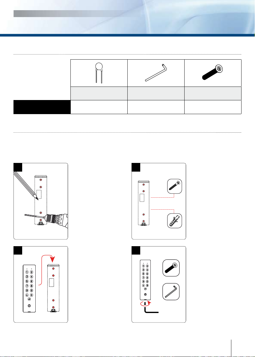
INSTALLATION MANUAL
6cdvi.com
cdvigroup.com
C. CHANGING THE MASTER CODE
The master code is used only to enter
in programming mode.
1. Enter the master code twice.
(1 2 3 4 5 default value master code).
- The red LED lights on,
- 2 beeps are emitted to con rm
entry in programming mode.
2. Press A5 to modify the master code.
- The green LED lights on during 1 second,
- One beep is emitted,
- Enter the new 4, 5 or 6 digits master code,
- The green LED lights on during 1 second,
- One beep is emitted to con rm
that the master code is programmed.
3. Press B to exit from
the programming mode.
- The red LED lights off,
- 2 beeps are emitted to con rm
that the keypad is in stand-by
operating mode.
D. ADDING, CHANGING
OR DELETING A USER CODE
Group 1: From address 00 to address 59, relay output 1
Group 2: From address 60 to address 99, relay output 2
1. Enter the master code twice
(1 2 3 4 5 default value master code).
- The red LED lights on,
- 2 beeps are emitted to con rm entry
in programming mode.
2. To add a user code, enter the user
location (from 00 to 99).
-
If the user location is free, the green LED
lights on during 1 second and 1 beep
is emitted, enter the 4, 5 or 6-digits User code,
- If the user location is already programmed,
the red LED fl ashes 4 times,
- 4 beeps are emitted,
- Enter a new 4, 5 or 6-digits code,
- The green LED lights on during 1 second,
- A beep is emitted to con rm
the new user code.
4. To delete a User code enter
the user location.
- 4 beeps are emitted,
- Press 0 0 0 0 0 0 in 6-digits length code
or 0 0 0 0 0 in 5-digits length code
or 0 0 0 0 4-digits length code,
-
A beep is emitted to con rm the new user code.
NOTE: If the Pin code is already programmed
or is identical to the master code, the red LED fl ashes
4 times, then 4 beeps are emitted. Press B to exit
from the programming mode. 2 beeps are emitted to
confi rm that the key-pad is in stand-by operating code.
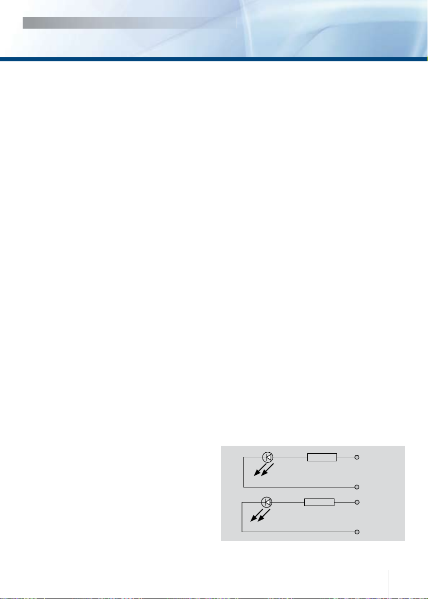
E. TIME OUTPUTS
This section allows to program
the illumination time and the Relay
activation time.
1. Enter the master code twice
(1 2 3 4 5 default value master code).
- The red LED lights off,
- 2 beeps are emitted to con rm
entry in programming mode.
2. Press A0 to program the key-in
keypad time and the keys lit time.
- The green LED lights on during 1 second,
-
1 beep is emitted,
- Enter the time in 10th
of second – 10 for 10
seconds up to 99 for 99 seconds
the backlighting dims 10 seconds
after the last keypress or switches off
after entering a valid code,
- The green LED lights on during 1 second,
- Press 00 for permanent illumination keys,
- One beep is emitted to validate the time.
3. Press A1 to program relay 1
output time (door release time).
- The green LED lights on during 1 second,
- 1 beep is emitted,
- For a latched output enter the time
in seconds – 01 for 1 second up to 99
for 99 seconds,
- Press 00 for a toggled output,
- The green LED lights on during 1 second,
- One beep is emitted to validate the time.
4. Press A2 to program relay 2
output time (door release time).
- The green LED lights on during 1 second,
- 1 beep is emitted,
- For a latched output enter the time
in seconds – 01 for 1 second up to 99
for 99 seconds,
- Press 00 for a toggled output,
- The green LED lights on during 1 second,
- One beep is emitted to validate the time,
- Press B to exit from programming mode,
- The red LED lights off,
-
2 beeps are emitted to con rm that the key-
pad is in stand-by operating mode.
4 times red LED fl ashing and 4 beeps
emitted indicate a data computing error.