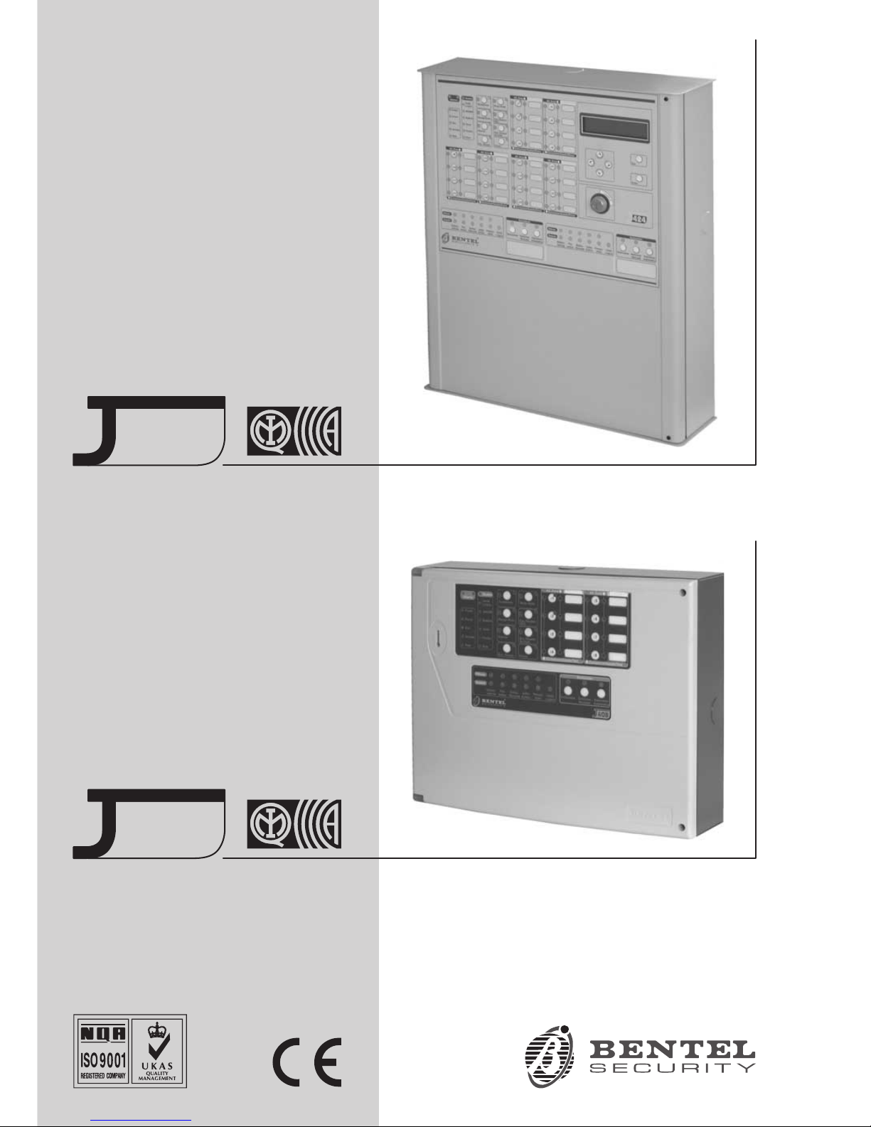
Bentel J424 User manual
®
INSTALLATION MANUAL
CONVENTIONAL
FIRE PANELS
424
408

This Control panel can be programmed using the respective Software J400 release 1.0 or higher.
BENTEL SECURITYsrl shall not assume the responsibility for damage arising from improper application or use.
This Control panel has been designed and manufactured to the highest standards of quality and performance.
Installation of this Control panel must be carried out strictly in accordance with the instructions described in this manual, and
in compliance with the local laws and bylaws in force
The J424 and J408 Control panels comply with the essential requirements of standards EN54-2;EN54-4.
The J424 and J408 Control panels, all their accessories and functions, except those listed below and unless otherwise specified
(see notes marked A), are IMQ Security Systems Grade II Listed.
The J400-EXT Extinguishment Module is not IMQ Security Systems Grade II Listed.
BENTEL SECURITY srl reserves the right to change the technical specifications of these products without prior notice.

INDICE
INTRODUCTION 5
The J424 and J408 Control panels 5
Accessory Items 5
Description 5
Inputs 5
Outputs 6
Operating features 6
Interface 7
Extinguishment Module 8
Access to Signalling and Commands 8
Power Supply 8
IDENTIFICATION OF PARTS 9
The Status LEDs 9
Description of Parts 14
Description of the Control keys 20
INSTALLING THE CONTROL PANEL 21
Installing accessory boards 21
Installing Extinguishment Modules 21
Installing Expander Module Kit (for J424 ONLY) 22
Display Module (for J424 and J400-REP ONLY) 24
Installing Repeaters 25
Installing the Control panel 25
Description of the Terminals 25
Main Board and Expander Board terminals 25
Main Board Terminals 26
Extinguishment Module Terminals 28
Extinguishment Module 4
Pre-extinguishment Phase 5
Extinguishment Phase 5
Manual Extinguishment 5
Disable Extinguish. button 5
Disable Manual Extinguish. button 5
The System Wiring 29
Connecting Fire Detectors 29
Connecting Call-points 30
Connecting Gas Detectors 30
Connecting Signalling Devices 31
Connecting a Repeater 32
Connecting Extinguishment Modules 33
Connecting a Power Supply 34
Connecting the Mains Supply 34
Thermal Probe 35
Maintenance 35

PROGRAMMING FROM A PC 37
Enrolling: Expander Modules 37
Enrolling: Extinguishment Modules 37
Activation Mode 38
Times 38
Zones 38
Manual Extinguishment Input 38
Disable Extinguishment Input 38
Pressure Switch Input 38
Enrolling: Power Supply Stations 38
Enrolling: Repeaters and LCD Modules 38
Zones 39
Thresholds 39
Options 40
Times 40
Outputs 40
NAC1 Output 40
NAC2 Output 40
ALARM Output 40
OC Output Events 41
DL Output 41
Panel Settings 41
Day/Night 41
Reset 42
User Code 42
Alarm Verification Time 42
Night Mode Silence Time 42
Mains Failure Signalling Delay 42
Date/Time 42
Downloading 43
PROGRAMMING FROM THE PANEL 45
Accessing the Programming session 45
Exiting the Programming Session 45
The “ZONES” Programming Phase 46
The “TIMES” Programming Phase 46
The “OUTPUTS” Programming Phase 47
The “PANEL” Programming Phase 48
User Code (Key/LED 1) 48
Day Mode (Key/LED 2) 48
Night Mode (Key/LED 4) 48
Clock (Key/LED 5) 48
Date (Key/LED 7) 48
Mains Off Delay (Key/LED 8) 48
The “VARIOUS” Programming Phase 48
Stabilization Time (Key/LED 1) 49
Reset Time (Key/LED 2) 49
Silenceable Outs (Key/LED 4) 49
Configuration 1 (Key/LED 5) 49
Configuration 2 (Key/LED 7) 49
The “MODULES” Programming Phase 49
Extinguish. time (Key/LED 1) 49
Pre-exting. time (Key/LED 2) 50
Activation Zones (Key/LED 4) 50
LCD Module 50
Programming Mode Address 50
Zones Descriptions 50
Strings Update 50
Date Format 50
QUICK GUIDE 51
Technical features 51
Description of the terminals 51

INTRODUCTION
The J424 and J408 Control panels
The reduced complexity J424 and J408 Fire Control
panels are the fruit of attentive research and installer
perception. The winning combination of expert wor-
kmanship, high quality materials and essential links
among vital components provide maximum installation
flexibility and performance.
The components of these Control panels operate as in-
tended when the external ambient conditions comply
with the requirements of class 3k5 of IEC 721-3-3:1978.
The J424 and J408 Control panels provides the follo-
wing features: 8 Supervised/Bypassable input zones
(the J408-2 provides 2 and the J408-4provides 4);
2 Supervised/Silenceable/Bypassable fire outputs;
1 Silenceable fire output and 1 Silenceable/Bypassable
fault alarm output.
The J424 model has been especially designed for me-
dium to large residential and commercial applications.
It supports two 8 zone Expander Modules (providing a
total of 24 zones); two Extinguishment Modules and an
LCD Module and provides housing for two 12 V, 17 Ah
batteries. This model is powered by a 2.5 A switching
power supply.
The J408 model has been especially designed for small
residential and commercial applications. It is available
with2(TJ408-2),4(J408-4) or 8 zones (J408-8).
It supports 1 Extinguishment Module and provides hou-
sing for two 12 V, 7 Ah batteries. This model is powered
by a 1.5 A switching power supply.
nAccessory Items
J400-EXP8 Expander Module Kit. This kit comprises
an 8 zone Expander Module and an Expander Control
board. The Expander Module contains most of the
electronic circuitry and electrical terminals whereas the
Expander Control board provides the command keys
and status LEDs of the Expander Module zones.
The Expander Module and Expander Control board are
intended for connection to the Main board of the Control
panel. In the event of an alarm, the Expander Module
will signal the status of its inputs to the Main board
which will activate the fire warning and fire control devi-
ces and generate signalling on the Expander Control
board. The J424 accepts TWO J400-EXP8 Expander
Modules Kits.
J400-EXT Extinguishment Module
False activation of fire extinguishment devices may ca-
use unnecessary inconvenience to end-users and se-
rious damage to property. The J400-EXT Extingui-
shment Module aims at the reducing the false alarm rate
by verifying alarm conditions before activating the extin-
guishment devices.
The J408-8,J408-4 and J408-2 Control panels support
ONE Extinguishment Module Kit, whereas the J424
Control panel supports TWO.
AThe J400-EXT Extinguishment Module IS NOT an
IMQ-SECURITY SYSTEMS listed product.
J400-LCD Display Module
This board has 6 scroll keys and a two-line backlit LCD
(16 characters per line) which provides written informa-
tion regarding the system status.
J400-REP Repeater panel
This Repeater panel is intended for connection (via 4
wires) to J424 and J408-8 Control panels. It provides all
the visual and audible warnings generated by the Con-
trol panel and allows end-users to manage the system
from a remote location (up to 1000 metres from the
Control panel). The J424 and J408-8 Control panels
support up to FOUR Repeater panels.
Software Management Sofware
This user-friendly software application (Windows) of-
fers a quick and easy way to program the Control panel
and provides event logger and print-out functions.
Description
nInputs
This Control panel has special inputs (detection zones)
for fire detection devices, such as conventional fire de-
tectors (i.e. devices which resemble the operating
mode of open contacts during standby status and resi-
stors during Alarm status) and similar devices, such as
Callpoints and gas detectors.
The Control panel considers its inputs to be in standby
status when they pull-down to 0 V with a 3900 ohm resi-
stance. The inputs can detect and signal Automatic
Alarms (generated by fire detectors), Manual Alarms
(generated by Callpoints), shorted lines (generated by
detector faults) and interrupted lines (generated by the
removal of detectors from their bases).
INTRODUCTION 5

AIMQ-SECURITY SYSTEMS certification applies
ONLY when no more than 30 devices are connec-
ted to each zone, and no more than 512 devices IN
ALL are connected to the Control panel.
nOutputs
AThis Control panel accepts devices that operate
within SELV limits ONLY.
This section describes how the Control panel outputs
operate.
Supervised outputs The Control panel will be able to
detect and signal short-circuits and power supply inter-
ruptions on this type of output.
Bypassable outputs The user will be able to disable
(by means of the respective key) this type of output.
Silenceable outputs The user will be able to stop (via
the Silence key) this type of output
The outputs can be silenced for an indefinite period (du-
ring Day Mode) or, for the programmed Silence Time
(during Night Mode).
This Control panel provides the following alarm outputs:
Øtwo Supervised/Silenceable/Bypassable outputs
(NAC1 and NAC2 terminals) with positive polarity
(27.6 V) during alarm status;
Øone Silenceable/NON-Supervised/NON-Bypassable
Volt-free changeover contact (ALARM terminals) for
devices which cannot be connected directly to NAC1
or NAC2;
Øone Supervised/Bypassable/NON-Silenceable output
(DL terminal), intended for use with telephone devices
that pull-down to 0 V (negative) in the event of an alarm;
Øone Silenceable/NON-Supervised/NON-Bypassable
output for each input zone (terminals R1,R2, ..., R8)
that will pull-down to 0 V (negative) when the respecti-
ve zone generates an alarm. These outputs allow se-
lective action, as they activate only the devices
connected to the zone concerned.
+The NAC1,NAC2 and DL outputs comply with
EN54-2.
This Control panel also provides:
Øone Silenceable/NON-Supervised/NON-Bypassable
Volt-free changeover contact (TROUBLE terminals)
that will activate in the event of trouble;
Øone NON-Supervised/NON-Bypassable/NON-Silen-
ceable open-collector output (OC terminal) that will
pull-down to0V(negative) when the associated
event occurs (Alarm, Pre-alarm, Fault, Reset,
Bypass, Test or Double knock);
Øone NON-Supervised/NON-Bypassable/NON-Silen-
ceable changeover contact (PL terminal) that will
pull-down to0V(negative) in the event of power fai-
lure to the Control panel.
nOperating features
Pre-alarm If a zone generates an alarm during Day
Mode (Night Mode LED OFF), the Control panel will start
the Pre-alarm Time. This status will be signalled by:
Øaslow intermittent beep;
Øblinking on the LED of the Zone Alarm that genera-
ted the Alarm;
Øglowing on the Pre-al. LED;
Øactivation of the NAC1 and NAC2 outputs — in ac-
cordance with programming;
ØNegative pull-down to0VontheRterminal of the
zone that generated the Alarm, that is, if the
Pre-alarm on R output option is enabled;
ØNegative pull-down to 0 V on OC terminal, that is, if it
is programmed to signal Pre-alarm.
+This Control panel will generate an Instant Alarm if
alarm conditions are detected during Night Mode
(Night Mode LED glowing) or, if an alarm is trigge-
red from a Callpoint connected to a zone enabled
for Call point Priority (i.e. the Call point Priority
option ENABLED).
During Pre-alarm status, all persons on the premises
(Access Level 1 — refer to “Access to signalling and
commands”) will be able to:
Øactivate an Evacuation Alarm by pressing and hol-
ding the Ack./Evac. key for AT LEAST 5 seconds.
During Pre-alarm status, Key and PIN Code users
(Access Level 2 — refer to “Access to signalling and
commands”) will be able to:
Øadd the Investigation Time to the Pre-Alarm Time
by pressing (for LESS THAN 5 seconds)the
Ack./Evac. key;
Øactivate an Evacuation Alarm by pressing and hol-
ding the Ack./Evac. key for AT LEAST 5 seconds;
Østop the Silenceable outputs and interrupt the
Pre-alarm Time by pressing the Silence key.
During Silence status (Silence LED glowing), it is pos-
sible to use the Silence key to release the Silenceable
outputs and restart Pre-alarm Time or, use the Reset
key to restore standby status.
+If the Control panel is operating in Night Mode
(Night Mode LED glowing), the Control panel will
exit Silence status automatically when the pro-
grammed Night mode Silence time expires.
Alarm The Control panel will generate an alarm when the
Pre-Alarm Time expires. Alarm status will be signalled by:
Øafast intermittent beep;
Øglowing on the LED of the Zone Alarm that genera-
ted the Alarm;
Øglowing on the Alarm LED;
Øactivation of the NAC1 and NAC2 outputs — in ac-
cordance with programming;
ØNegative pull-down to0VontheRterminal of the
zone that generated the Alarm;
ØNegative pull-down to0VontheOC terminal, that is,
if it is programmed to signal Alarm status.
6 Conventional Fire Panels J424/J408

+The Control panel will activate the DL output when
the programmed Alarm Signalling delay expires.
During Alarm status, Key and PIN Code users (Access
Level 2 — refer to “Access to signalling and com-
mands”) will be able to:
Østop the Silenceable outputs by pressing the Silence
key.
During Silence status (Silence LED glowing), it is pos-
sible to use the Silence key to release the Silenceable
outputs, and the Reset key to restore standby status.
+If the Control panel is in Night Mode (Night Mode
LED glowing), the Control panel will exit Silence
status when the programmed Night mode Silence
time expires.
Trouble This Control panel can detect and signal the
following Trouble:
ØInput zone shorted or open;
ØSupervised zone shorted or open;
ØControl panel blocked;
ØOutput 24V or 24R shorted;
ØLow battery, battery trouble or disconnected battery;
ØGround fault;
ØCommunication trouble with peripherals;
ØMains failure.
Fault conditions will be signalled by:
Øaslow intermittent beep (at 1 second intervals);
Øglowing on the Fault LED;
Øfast blinking on the LED of the “component” concer-
ned (the Logic Unit LED will glow to signal “Control
panel blocked”);
Øactivation of the Fault output (TROUBLE terminals);
ØNegative pull-down to 0 V on OC terminal, that is, if it
is programmed to signal Fault.
The Fault output (TROUBLE terminals) and OC out-
puts (if duly programmed) will restore to standby auto-
matically when fault conditions clear.
Under certain circumstances, fault conditions may clear
spontaneously, if this occurs, the event will be stored in
the memory until the Control panel Resets.
Stored Fault events will be signalled by:
Øslow blinking on the LEDs of the “component” con-
cerned.
Silence This Control panel provides a Silence key
which can be used to restore the Silenceable outputs to
standby status:
ØR1, R2, ..., R8
ØNAC1 and NAC2
ØALARM
ØTROUBLE
Silence status will be signalled by:
Øan audible signal (lasting 1 second) followed by a
long pause (lasting 5 seconds);
Øglowing on the Silence LED.
Silence status will be held until the Silence key is pres-
sed again or, if the Control panel is operating in Night
Mode, until the programmed Night mode Silence time
expires, or until a new Alarm or Trouble condition is de-
tected.
+ONLY Key and PIN Code Users (Access Level 2)
can SILENCE the Silenceable outputs.
Disable This Control panel provides keys which can be
used to disable the bypassable inputs and outputs:
ØZ1,Z2, ... Z24 can be used to bypass (exclude) their
respective zones;
ØDisab./Fault NAC can be used to bypass outputs
NAC1 and NAC2;
ØDisab./Fault Telecom can be used to bypass the DL
output.
DISABLED zones cannot generate alarms or warnings
of any kind, and DISABLED outputs cannot be activa-
ted.
Disabled status will be signalled by:
Øglowing on the Disab. LED;
Øglowing on the LED of the respective zone or output
(see LEDs: Disabled/Fault/Test, Disab./Fault NAC
and Disab./Fault Telecom).
+ONLY Key and PIN Code Users (Access Level 2)
can DISABLE zones and/or outputs.
Reset Resetting the Control panel will restore the out-
puts to standby status, delete the memory, and interrupt
the power supply to terminals Z1, Z2, ..., Z8 and 24R for
the programmed Reset Time.
+ONLY Key and PIN Code Users (Access Level 2)
can Reset the system. Fire alarms must be Silen-
ced (via the Silence key) before Reset.
Fault conditions can be Reset directly (via the Re-
set key).
nInterface
Visual Signalling The system status will be signalled
on the Control panel LEDs as follows:
GREEN indicates normal operating conditions;
AMBER indicates specific operating modes (for exam-
ple Day or Night mode), and/or Fault conditions;
RED indicates Alarm conditions.
Memory The Control panel will signal Alarm/Fault
events until the system Resets, even if the event clears
in the meantime.
Stored events will be signalled by:
Øslow blinking on the LED concerned.
Display The J424 Control panel can house the
J400-LCD Module. This module provides written infor-
mation regarding the system status, and the cause of
faults on inputs and outputs (short-circuit, interruption
etc.).
INTRODUCTION 7
Audible Signalling The Buzzer will signal the Control
panel status as follows:
Status Sound Pause Description
Pre-alarm 0.5 s 0.5 s Intermittent beep
Alarm 0.2 s 0.2 s Fast Intermittent beep
Fault 1 s 1 s Slow Intermittent beep
Silence 1 s 5 s Long beep/Long pause
Reset 0.5 s 0.1 s Short beep/Short
pause
Test 1 s 3 s Long beep/Long pause
Test This key will allow ALL users to test the Control
panel Buzzer and LEDs (Access level 1), and Key and
PIN Code Users to test the zones (Access level 2).
To test a zone: press the respective Zone key (Z1,Z2, ...,
Z24) and the Test key simultaneously.
nExtinguishment Module
This section describes how the J400-EXT Extingui-
shment Module operates.
Activation Mode The Extinguishment devices may be
activated by alarm conditions on ONE of the program-
med zones (OR Mode), at least TWO of the program-
med zones (At least two Mode), or ALL of the program-
med zones (ALL Mode).
Pre-Extinguishment If the programmed ‘Activation
Mode’ conditions occur, the Extinguishment Module will
start the Pre-Extinguishment phase (indicated by glo-
wing on the Pre Ext. LED and by activation of the Modu-
le PR outputs) but will not activate the respective Extin-
guishment devices immediately, thus allowing users to
verify the Alarm.
Extinguishment If the ‘Activation Mode’ conditions
are still present when the programmed Pre-Extingui-
shment time expires, the Extinguishment Module will
activate the Extinguishment phase (indicated by glo-
wing on the Electrovalve LED and by the activation of
the Module’s AE output). The Extinguishment devices,
(connected to the Module’s EV output) will stay On until
the alarm conditions cease, or until the programmed
Extinguishment Time expires (i.e. if the Bistable option
is disabled), or until the Disable Extinguish. key is
pressed.
Auxiliary Supervision Inputs The Extinguishment
Module provides supplementary supervision inputs for
Extinguishment Inhibition, Manual Extinguishment and
Pressure Switch control. These Supervised inputs
must pull down to0V(negative) with a 3.900 ohm resi-
stance during standby status. In the event of interrup-
tion or short-circuit, these inputs will generate a war-
nings on the LED concerned.
nAccess to Signalling and Commands
There are 4 access levels, in compliance with the Fire
Safety Regulations in force.
Access Level 1 Viewing: ALL persons can view the
Control panel status.
Access Level 2 Operating the system (PIN Code ente-
red or Key turned in the Keyswitch): ONLY Key and PIN
Code Users can operate the system.
Access Level 3 Opening the Control panel: ONLY
Qualified persons with authorization are allowed to
open the Control panel door (requires removal of the
screws) for maintenance purposes.
Access Level 4 Repairing or replacing the PCB:
ONLY the Manufacturer should be allowed to repair or
replace the PCB.
nPower Supply
The power supply system of the J424 and J408 Control
panels complies with EN54-4.
Both models are powered by the Mains (230 V, 50 Hz):
Øthe J408 model has Switching Power Supply which
supplies up to 1.5 A at 27.6 V;
Øthe J424 model has Switching Power Supply which
supplies up to 2.5 A at 27.6 V;
Both models can house two 12 V batteries which, when
connected in series, will supply 24 V to the Control pa-
nel and peripherals in the event of black-out, and will
also provide any pickup currents which exceed the ma-
ximum current supplied by the Switching Power Supply.
Power Supply:
Øthe J408 model can house two 7 Ah batteries (YUASA
NP 7-12 FR model or similar — flame class UL94-V2
or higher);
Øthe J424 model can house two 17 Ah batteries
(YUASA NP 17-12 FR model or similar — flame class
UL94-V2 or higher).
This Control panel can detect, signal and store in me-
mory the following power faults: shorted 24V or 24R
outputs (24V/24R LED); Low battery, Battery fault or
Battery disconnected (Battery LED), Ground fault
(Ground LED) and Mains failure (Mains LED).
+The “Battery Disconnected” fault may be signalled
with a delay of up to 1 minute. The “Mains” fault will
be signalled when the programmed delay expires.
8 Conventional Fire Panels J424/J408

IDENTIFICATION OF PARTS
The Status LEDs
The following section describes how the Control panel
LEDs operate, and the actions that can be taken during
the various phases signalled on the LEDs. During
standby status ONLY the GREEN Mains LED should
be On (glowing).
+Some LEDs indicate more than one status, howe-
ver, in most cases the LEDs signal as follow:
ON (glowing) indicates DISABLED status;
Fast blinking indicates a FAULT condition;
Slow blinking indicates an ALARM/FAULT event
in memory.
LED DESCRIPTION
Alarm Glowing indicates Alarm status. In the event of an Alarm, the Control panel will activate the unbypas-
sed alarm outputs..
Pre-al. Glowing indicates Pre-alarm status.
Test Glowing indicates Test conditions on at least one zone.
Disab. Glowing indicates the Disabled status of the NAC,Telecom, Zone and Extinguishment outputs, or inhi-
bition of Manual or Automatic Extinguishment options.
Telecom Glowing indicates that the Telephone device output is active (negative pull-down to0Vonterminal
[DL]).
Green
Mains
OFF indicates Mains failure (230 V).
IMPORTANT: Power must be restored before the batteries empty.
Fault Glowing indicates one of the following Faults: Blocked Control panel; Shorted 24V or 24R output;
Empty Batteries; Disconnected Battery; Ground Fault; Mains Failure; Zone Trouble; Shorted or Open
NAC or DL output; Extinguishment Module Trouble; Peripheral Trouble.
Logic Unit Glowing indicates Blocked Control panel. IMPORTANT: Maintenance required
24V/24R Fast blinking indicates Shorted 24V or 24R output.
Battery Fast blinking indicates Batteries empty, disconnected or faulty. If this condition persists, the batteries
will be unable to function as intended in the event of blackout, therefore, replacement is required.
Ground Fast blinking indicates a Voltage leakage to Earth.
IMPORTANT: Check wiring insulation.
Periph. Fast blinking indicates communication trouble with peripherals.
Red Mains Fast blinking indicates Mains failure (230 V) or Switching Power supply fault. During this condition,
the Control panel will be powered by the batteries. Mains failure is also signalled on the Green Mains
LED (OFF), however, this LED also signals Mains Failure in Memory (Slow blinking).
Silence Glowing indicates that Silenceable outputs (terminals [NAC1], [NAC2], [DL], [TROUBLE], [ALARM] (if
duly programmed) and [Rn] (if duly programmed) have been manually forced to standby by means of
the respective key.
Ack./Evac. Glowing indicates that the programmed Investigation time is running.
Reset Glowing indicates that Reset operations cannot be carried out.
Night Mode Glowing indicates that the Control panel is operating in Night Mode.
Disab./Fault
NAC
Glowing indicates that the Supervised, Silenceable Fire Alarm outputs (terminals [NAC1] and
[NAC2]) have been disabòled by means of the respective key, therefore, in the event of alarm will not
be activated.
Fast blinking indicates that at least one of the Supervised, Silenceable Fire Alarm outputs (termi-
nals [NAC1] and [NAC2]) is shorted or open.
Disab./Fault
Telecom
Glowing indicates that the telephone device output (terminal [DL]) has been disabled by means of the
respective key, therefore, in the event of an alarm will not be activated.
Fast blinking indicates that the telephone device output (terminal [DL]) is shorted or open.
Disabled/
Fault/
Test
Glowing indicates that the respective zone has been disabled by means of the respective key, therefo-
re, will be unable trigger alarms. Fast blinking indicates that the respective zone is shorted or open,
therefore, unable to detect alarm conditions.
Zone Alarm Glowing indicates that the respective zone has detected alarm conditions.
Table 1 Description of the status LEDs ... (continued on page 20)
MSACMBLIJ424-8 0. 0
Esc
Enter
Fault
Logic
Unit
Battery
Ground
Mains
Periph.
Pre-al.
Disab.
Mains
Telecom
Test
Silence Night Mode
Ack./Evac. Disab./Fault
NAC
Reset Disab./Fault
Telecom
Disab. Buzzer Test
12
3
5
8
0
4
7
9
6
Disabled/Fult/Test Disabled/Fult/Test
z1 z5
z4 z8
z3 z7
z2 z6
Zone Alarm Zone Alarm
24V/24R
Alarm
Disabled/Fult/Test Disabled/Fult/Test
z9 z13
z12 z16
z11 z15
z10 z14
Zone Alarm Zone Alarm
Disabled/Fult/Test Disabled/Fult/Test
z17 z21
z20 z24
z19 z23
z18 z22
Zone Alarm Zone Alarm
®
424
Extinguish. Automatic
Extinguish.
Manual
Extinguish.
Electro-
valve
Pre-
Ext.
Manual
Ext.
Disab.
Ext.
Pres.
Switch
Logic
Unit
Disable
Fault
ON
Extinguish. Automati
c
Extinguis
h
Manual
Extinguish.
Electro-
valve
Pre
Ext.
Manual
Ext.
Disab.
Ext.
Pres-
Switch
Logic
Unit
Disable
Fault
ON
L
i
v
e
l
l
o
2
121 2 3
2512
a)
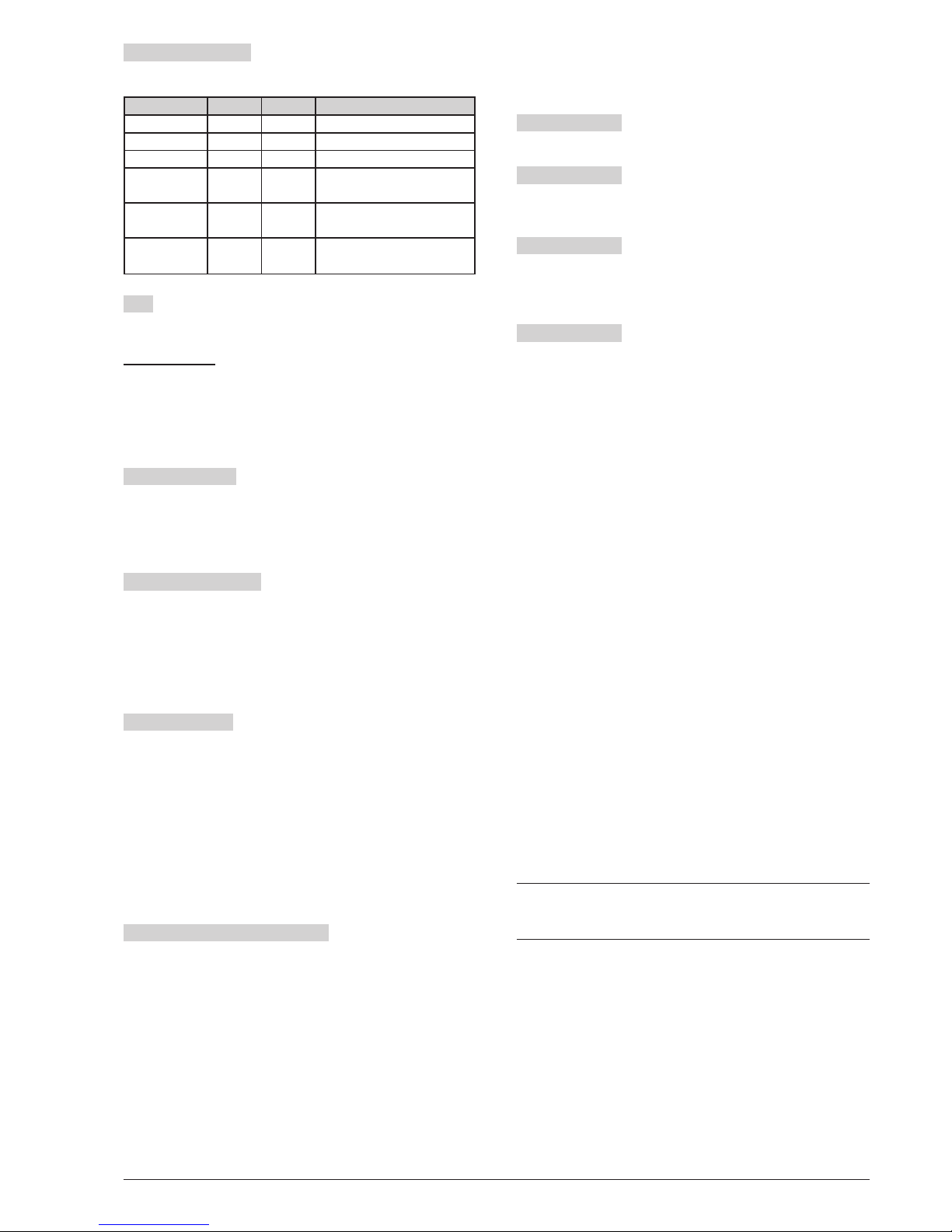
Figure 1 Front view of the J424 Control panel J424 (a), J408 Control panel (b) and J400-REP Repeater (c)

B
MSACMBLIJ408-8 0.0
Extinguish. Automatic
Extinguish.
Manual
Extinguish.
Electro-
valve
Pre
Ext.
Manual
Ext.
Disab.
Ext.
Pres.
Switch
Logic
Unit
Disable
Fault
ON
®
408
MSACMNEIJ408-8 0.0
Fault
Logic
Unit
Battery
Ground
Mains
Periph.
Pre-al.
Disab.
Mains
Tele com
Test
Silence Night Mode
Ack./Evac. Disab./Fault
NAC
Reset Disab./Fault
Telec om
Disab. Buzzer Test
12
3
5
8
0
4
7
9
6
Disabled/Fault/Test Disabled/Fault/Test
z1z5
z4z8
z3z7
z2z6
Zone Alarm Zone Alarm
24V/24R
Alarm
c
h.
MSACMBLIJ400-REP a.0
Esc
Enter
Fault
Logic
Unit
Battery
Ground
Mains
Periph.
Pre-al.
Disab.
Mains
Telecom
Test
Silence Night Mode
Ack./Evac. Disab./Fault
NAC
Reset Disab./Fault
Telecom
Disab. Buzzer Test
12
3
5
8
0
4
7
9
6
Disabled/Fault/Test Disabled/Fault/Test
z1 z5
z4 z8
z3 z7
z2 z6
Zone Alarm Zone Alarm
24V/24R
Alarm
Disabled/Fault/Test Disabled/Fault/Test
z9 z13
z12 z16
z11 z15
z10 z14
Zone Alarm Zone Alarm
Disabled/Fault/Test Disabled/Fault/Test
z17 z21
z20 z24
z19 z23
z18 z22
Zone Alarm Zone Alarm
®
L
i
v
e
l
l
o
2
400 REP
5 1 22 4
44
41 1
b)
4 4
4 435 2
c
)
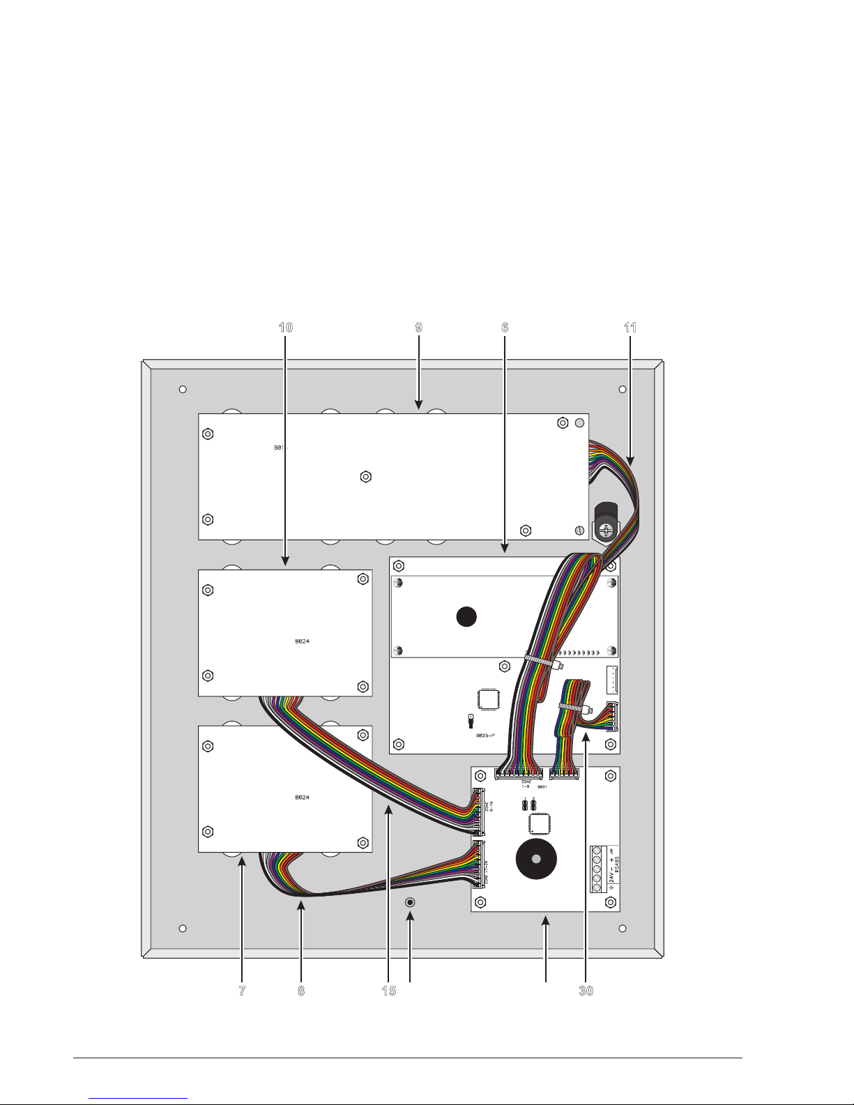
IDENTIFICATION OF PARTS 11

C
NONC
678 10 11
262728293031
9
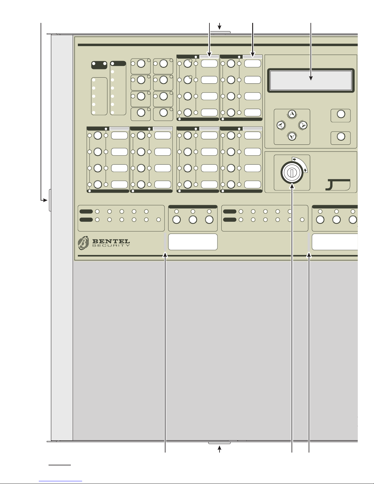
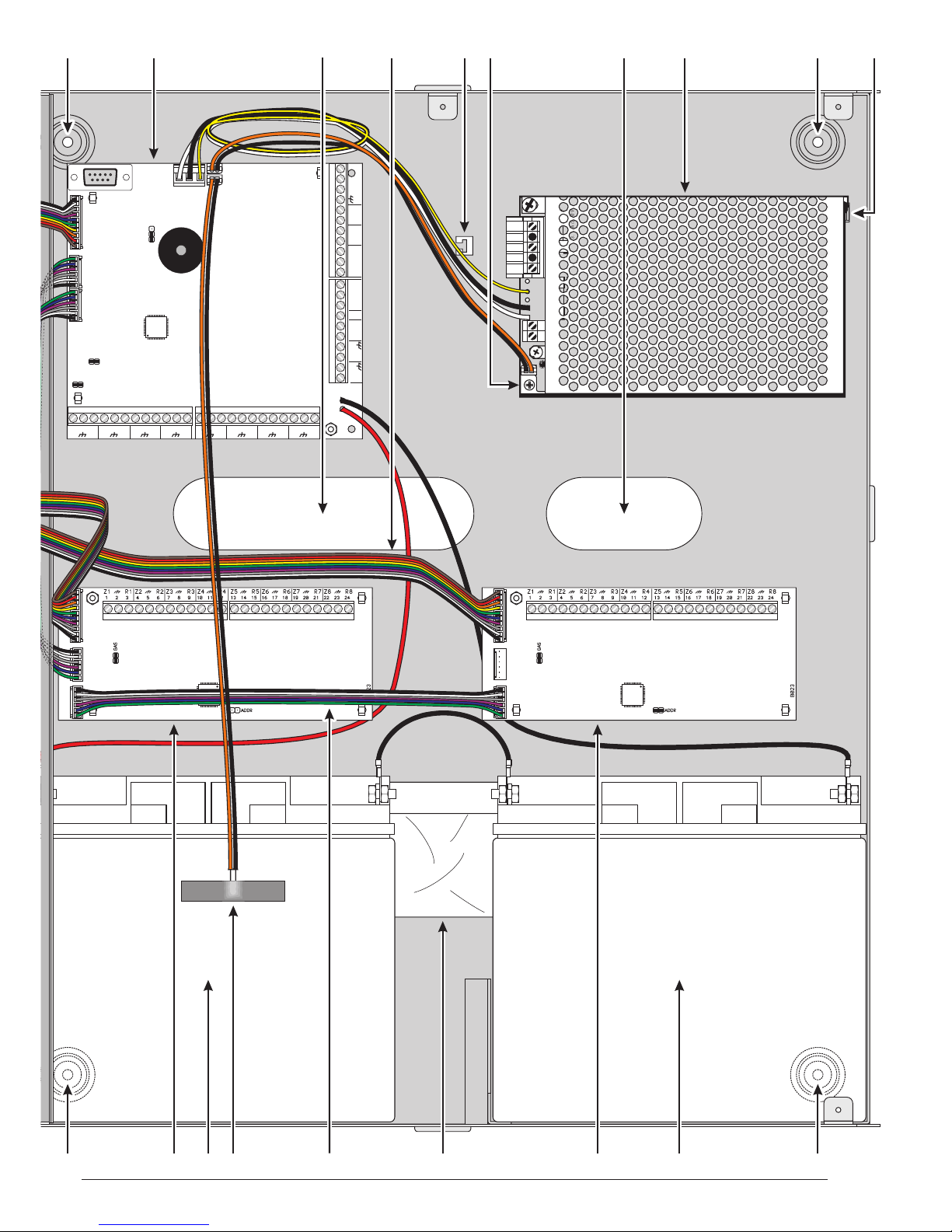
Figure 2 Maximum configuration of the J424 Control panel
Z1 R1
123
Z2 R2
45 6
Z3 R3
78 9
Z4 R4
10 11 12
DL24V
27 28 29 30 31
PL ALARM
NO NC C
TROUBLE
NO NC C
-
+
-
+
NAC1 NAC2
Z5 R5
13 14 15
Z6 R6
16 17 18
Z7 R7
19 20 21
Z8 R8
22 23 24
26
24R OC
+
-
RS485
V
24
PRG
B016
GAS
EF
R
AC/N
FG
+V
GND
B+
L
B–
GND
+V
AC/L
F3.15A/25ØV
F6.3A/25ØV
20
12 13 14 15 17 14 18 12 19
21222324202512 12
16
IDENTIFICATION OF PARTS 13
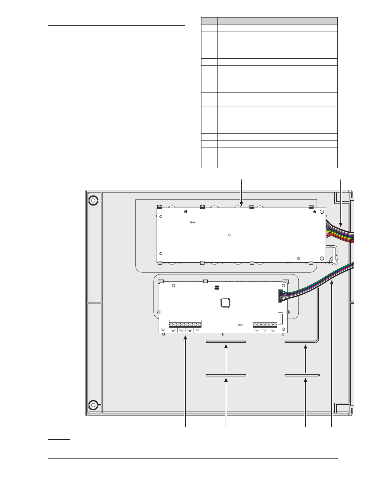
Description of Parts
This section describes the components of the J424 and
J408 Control panels, and J400-REP Repeater.
Unless otherwise stated, the numbers in boldface in this
Manual refer to the Tables ands Diagrams in this sec-
tion.
The parts identification numbers in the diagrams go cloc-
kwise. The white numbers refer to parts which are com-
mon to several of the system devices, therefore, are
described the first time they are encountered only.
P. Description
1Surface Cable conduit entry
2Zone label slots
3Display
4Door screws
5Keyswitch (Access Level 2)
6Display module (accessory item)
7Expander Control board (LEDs and keys) of
Expander no. 2 (accessory item for J424)
8Flat cable (accessory item for J424): for the
Expander Control board connection
9Main Control board (LEDs and keys) of zones
1 through 8
10 Expander Control board (LEDs and keys) of
zones 9 through 16 (accessory item forJ424)
11 Flat cable: for the Main Control Board connec-
tion (zones 1 through 8)
12 Anchor screw locations
13 Main board (2, 4 or 8 zones)
14 Chased cable conduit entry
15 Flat cable (accessory item for J424): for the
Expander Control board connection
14 Conventional Fire Panels J424/J408
C
NONC
9
323228 27
11
Figure 3 Maximum configuration of the J408 Control panel
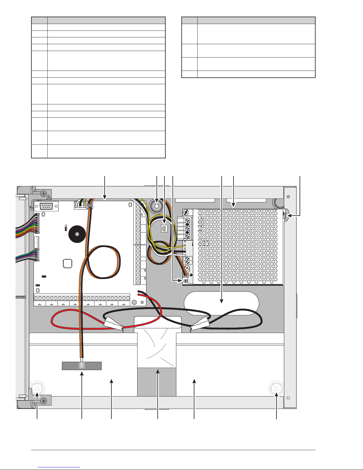
P. Description
16 Anchor for 230 V power supply wires
17 Switching power supply screws
18 Switching power supply/Battery charger
19 Switching power supply support
20 Batteries (NOT supplied!):
J408 =two 7Ah@12V
J424 = two 17 Ah @ 12 V
21 Expander no. 1 (accessory item)
22 Bag containing keys, resistors and diodes
23 Flat cable (accessory item): for the Expander
Module no. 1 to Expander Module no. 2 con-
nection
24 Thermal probe (accessory item)
25 Expander Module no. 2 (accessory item)
26 Flat cable(accessory item): for the Expander
Module no. 1 to Main board connection
27 Flat cable (accessory item): for the Extingui-
shment Module to Main board connection
28 Extinguishment Module no.1 (accessory
item)
P. Description
29 Flat cable (accessory item): for the Extingui-
shment Module no. 1 to Extinguishment Mo-
dule no. 2 connection
30 Flat cable (accessory item): for the Display
Module connection
31 Extinguishment Module no.2 (accessory
item)
32 Wire run
IDENTIFICATION OF PARTS 15
Z1 R1
12 3
Z2 R2
456
Z3 R3
789
Z4 R4
10 11 12
DL24V
27 28 29 30 31
PL ALARM
NO NC C
TROUBLE
NO NC C
-
+
-
+
NAC1 NAC2
Z5 R5
13 14 15
Z6 R6
16 17 18
Z7 R7
19 20 21
Z8 R8
22 23 24
26
24R OC
+
-
RS485
V
24
PRG
B016
GASEF
R
AC/N
FG
+V
GND
B+
L
B–
GND
+V
AC/L
F2A/25ØV
F6.3A/25ØV
12
13 12 18
202012 24
17 1916 14
22
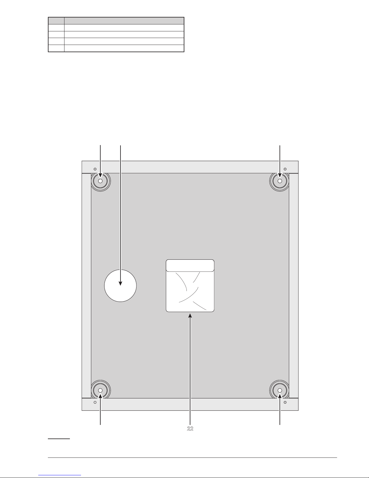
P. Description
33 Anchor screw location holes
34 Chased cable conduit entry
35 RS485 Interface
36 Soldered Earthing screw
16 Conventional Fire Panels J424/J408
a) 33
33
34 33
33
Figure 4 Maximum configuration of the J400-REP Repeater: a) backplate; b) frontplate (inside view)
IDENTIFICATION OF PARTS 17
C
NONC
36 35
b)
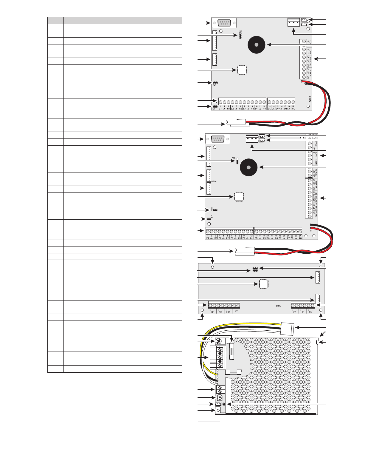
P. Description
37 Battery output voltage control output (connec-
ted at factory)
38 Thermal probe jack
39 Switching-power-supply jack (connected at
factory)
40 Buzzer
41 Terminal board
42 Extinguishment Module anchor holes
43 Address Jumper:
// = Extinguishment Module no. 1
oo = Extinguishment Module no. 2
44 Terminal board
45 Cable: connects the Switching power supply
to the Main board (connected at factory)
46 Switching-power-supply anchor
47 Switching-power-supply closure rivet
48 Mains indicator LED
49 Switching-power-supply anchor hole
50 Switching-power-supply output voltage con-
trol input (connected at factory)
51 Fine trimmer for the Switching-power-supply
output Voltage
52 Auxiliary power-supply terminals (27.6 V)
53 Mains power terminals (230V/50Hz)
54 Switching-power-supply screws
55 Switching-power-supply fuse — protects aga-
inst overload:
J408 = F 2A 250V
J424 = F 3.15A 250V
56 Jack for Extinguishment Module nr. 2 or the
Display Module
57 Microprocessor
58 Jack for the Main board or Display Module
59 Reserved Jumper — DO NOT REMOVE
60 Battery jacks
61 Jumper for Ground (Earth) fault detection:
// = Ground (Earth) fault monitored
oo = Ground (Earth) fault NOT monitored
62 Jumper — to be REMOVED when connecting
a 4-20 mA gas detector to terminal Z1
63 Jack for Extinguishment Module nr. 1 or the
Display Module
64 Expander Module jack
65 Programming Jumper:
PRG PRG
oOProgramming
OProgramming OEnabled
ODisabled o
66 Expander Control board jack (connected at
factory)
67 RS232 Serial Port
18 Conventional Fire Panels J424/J408
AC/N
FG
+VGND
B+
L
B–
GND
+V
AC/L
F 2A/25ØV
F6.3A/25ØV
38
67
40
41
37
39
37
38
39
41
40
41
42
43
44
42
45
47
48
65
66
63
4
1
61
60
67
66
64
65
63
61
4
1
60
4
2
59
58
56
4
4
4
2
55
53
52
51
50
4
9
a)
b)
c)
d)
54
46
57
62
57
62
57
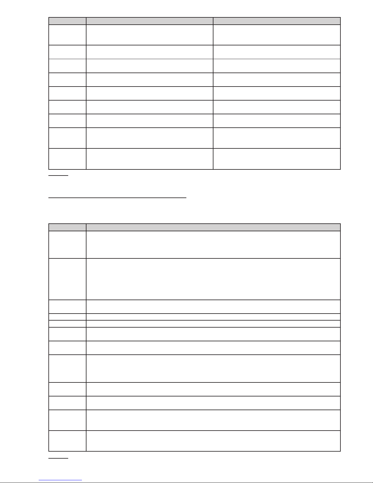
Figure 5 Identification of Parts: a) Main Board (2 or 4
zones); b) 8-zone Main Board; c) Extinguishment Mo-
dule; d) J408 Control panel Switching-power-supply

P. Description
68 Expander Module anchor holes (4)
69 Terminal strip
70 Address Jumper:
// = Expander Module no. 1
oo = Expander Module no. 2
71 Expander Control Board anchor holes (4)
72 Jack for the Expander Control Board to
Expander Module connection
73 Display Module anchor holes (5)
74 Jack for the connection between the Di-
splay Module and the consecutive periphe-
ral device
75 Jack for the connection between the Di-
splay Module and the preceding peripheral
device
76 Address Jumpers
77 Terminal strip
78 Buzzer
79 Jack for the Expander Control board (zo-
nes 17 to 24)
80 Jack for the Expander Control board of zo-
nes9to16
81 Jack for the Expander Control board of zo-
nes1to8
82 Display Programming Jumper:
// = Programming Disabled
oo = Programming Enabled
83 Jack for the connection between the
Expander Module and the consecutive pe-
ripheral device
84 Jack for the connection between the
Expander Module and the preceding pe-
ripheral device or Main Board
85 Expander Control Board jack
IDENTIFICATION OF PARTS 19
AC/N
FG
+V
GND
B+
L
B–
GND
+V
AC/L
F3.15A/25ØV
F6.3A/25ØV
68 68
85
84
83
68
69
68
70
71
72
71
71
71
73
74
75
73
73
73
82
73
a)
b)
c)
81
80
79
78
76
77
d)
e)
Figure 6 Identification of Parts: a) Expander Module; b)
Expander Control Board; c) Display Module; d) RS485
Repeater Interface; e) J424 Control panel Switching-po-
wer-supply
Description of the Control keys
The Control panel keys can be activated by Keyswitch
and PIN Code Users ONLY (Access level 2 — Key tur-
ned in keyswitch or PIN Code entered — refer to
“Access to Signalling and Commands”), unless otherwi-
se stated.
LED ON Fault
Electro-
valve
Glowing indicates “Extinguishment” in course Fast blinking indicates power supply failure to
the electrovalve connected to output EV, or that
the latter is either open or shorted
Pre
Ext.
Glowing indicates “Pre-Extinguishment” in cour-
se
Fast blinking indicates that terminals [+] and [–]
of output PR are either disconnected or shorted
Manual
Ext.
Glowing indicates that input EM has been activa-
ted
Fast blinking indicates that terminals [+] and [–]
of input EM are either disconnected or shorted
Disab.
Ext.
Glowing indicates that input IE has been activa-
ted
Fast blinking indicates that terminals [+] and [–]
of input IE are either disconnected or shorted
Pres.
Switch
Glowing indicates that the input PS has been ac-
tivated, due to low extinguishant gas pressure
Fast blinking indicates that terminals [+] and [–]
of input PS are either disconnected or shorted
Logic
Unit
—Fast blinking indicates “blocked” Extingui-
shment Board
Disable
Extinguish.
Glowing indicates “Extinguishment” is inhibited
Disable
Manual
Extinguish.
Glowing indicates “Manual Extinguishment” is
inhibited
Disable
Automatic
Extinguish.
Glowing indicates that “Automatic Extingui-
shment” is inhibited
Table 1 (continued from page 9) … Description of the LEDs
Key DESCRIPTION
Silence This key can be used to restore the Silenceable outputs to standby status (terminals [NAC1], [NAC2],
[DL], [TROUBLE], [ALARM — if duly programmed] and [Rn — if duly programmed]. Silence status
will be held until the Silence key is pressed again or, if the Control panel is operating in Night Mode,
until the Night mode Silence time expires or until a new Alarm/Trouble condition is detected.
Ack./ Evac. This key can be used to refresh the “Pre-Alarm Time” or trigger an Alarm:
For all persons on the premises: If this key is pressed for over 5 seconds during “Pre-Alarm Time”,
the system will generate an alarm.
For Key and PIN Code Users ONLY (Access level 2): If this key is pressed during “Pre-Alarm
Time”, the remaining Pre-Alarm Time will be refresh with the programmed Investigation Time.Ifitis
pressed for over 5 seconds during “Pre-Alarm Time”, the system will generate an alarm.
Reset This key can be used to reset the Fire detectors and restore all outputs to standby status (Supervi-
sed/Silenceable outputs, NON-Supervised/Non-Silenceable outputs and Alarm zone outputs).
Disab. Buzzer This key can be used to disable the buzzer. The buzzer will be re-enable if any kind of event occurs.
Night Mode This key can be used to switch from Day to Night Mode.
Disab./Fault
NAC
This key can be used to disable the Bypassable Fire alarm outputs (terminals [NAC1] and [NAC2]).
Disab./Fault
Telecom
This key can be used to disable the Telephone device output (terminal [DL])
Test This key can be used to test the zones, buzzer and LEDs . If this key is pressed (when the Control pa-
nel is functioning as intended), all the LEDs will Glow and the buzzer will emit a continuous beep.
For Access level 2 Users ONLY: If this key is pressed with the Disable key of a zone (z1,z2, .., z24)
it will activate the respective zone test phase.
z1 … z24 These keys can be used to disable their respective zones. Disabled zones will provide visual signal-
ling of fire and fault conditions but will not activate any outputs or store events in Memory.
Disable
Extinguish.
This key can be used to disable the “Extinguishment” function.
Disable
Manual
Extinguish.
This key can be used to disable the “Manual Extinguishment” function. If this function is disabled, it
will not be possible to activate Extinguishment function via the EM input.
Disable
Automatic
Extinguish.
This button can be used to disable the “Automatic Extinguishment” function. If this function is disa-
bled, the zones will not be unable to activate Extinguishment”.
Table 2 Description of keys
This manual suits for next models
1
Table of contents
Other Bentel Smoke Alarm manuals


