Bentel FireClass FC400PH User manual
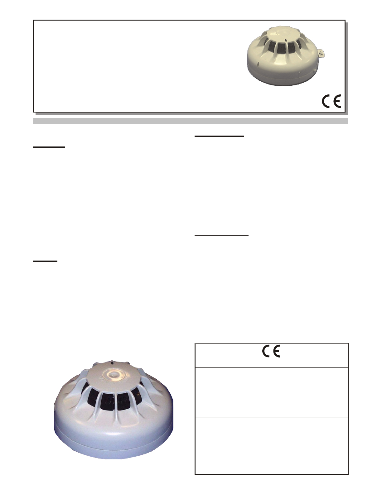
FC400PH
RILEVATORE OTTICO DI FUMO E TEMPERATURA INDIRIZZABILE
ADDRESSABLE OPTICAL SMOKE & HEAT DETECTOR
FC STREULICHT-WÄRMESENSOR
ISTSUBL3FC400PH 3.0 121109
FireClass
LEAFLET 120.415.951
DEUTSCH
Best.-Nr. 516.800.700
ANWENDUNG
Der Brandmelder FC400PH ist ein adressierbarer optischer Rauchund
Wärmesensor.
Der Streulicht-Wärmesensor FC400PH kann in verschiedenen
Betriebsmodi betrieben werden:
ØStreulicht
ØStreulichtauswertung, deren Empndlichkeit abhängig ist vom
Temperaturanstieg
ØWärmedierentialmelder
ØStatischer Wärmemelder
ØStreulicht + statischer Wärmemelder
Die Auswahl der Betriebsmodi erfolgt über die Konguration in der Zentrale.
Der Streulicht-Wärmesensor FC400PH kann auf folgende Meldersockel
aufgesteckt werden:
ØFC Meldersockel 5“: 517.050.017
ØFC Meldersockel 5“ mit Isolator: 517.050.718
ØFC Meldersockel mit Sirene: 516.800.710
MONTAGE
Der Sensor wird auf den Meldersockel aufgesetzt und durch eine Drehung im
Uhrzeigersinn bis zum Einrastpunkt in Betriebsposition gebracht. Durch eine
Drehung gegen den Uhrzeigersinn, bei gleichzeitigem Drücken des Stiftes seitlich
im Sockel, wird der Sensor in Parkposition gebracht.
Mit einer optionalen Entnahmesicherung rastet der Sensor in der Betriebsposition
fest ein und kann nur mit einem Spezialwerkzeug aus dem Meldersockel entfernt
werden.
TECHNISCHE DATEN
System-Kompatibilität:Adressierbares FC Brandmeldesystem
Elementtyp (Kennung): 10
Umgebungsbedingungen
Temperatur:-25...+70 °C
Rel. Luftfeuchte: max. 95% (ohne Betauung)
Abmessungen
Höhe: 43 mm
Durchmesser: 109 mm
ELEKTRISCHE DATEN
Spannungsversorgung aus der
Ringleitung: 20,0...40 V
Stromaufnahme
Bereitschaftszustand: 0,3 mA
Alarmzustand: max. 3,3 mA (mit LED)
ADRESSEINSTELLUNG
Im Auslieferungszustand ist die Adresse standardmäßig auf 255 gesetzt. Zum
Einstellen der individuellen Systemadresse kann das Handprogrammiergerät
FC490ST verwendet werden.
FC Streulicht-Wärmesensor — FC400PH
Abb.1:
0832
BENTEL SECURITY s.r.l.
Via Gabbiano, 22 - Zona Ind. S. Scolastica
64013 Corropoli (TE) - ITALY
09
0832-CPD-1279
EN 54-5:2000 + A1:2002
EN 54-7:2000 + A1:2002
Addressable photoelectric smoke and Class P heat
detector for use in fire detection and alarm systems in
buildings
FC400PH
and Heptane type fires respectively).These fires do however produce high heat
outputs with an associated rise in air temperature. The detector has been de-
signed to offer improved detection of such fires by detecting the rapid rate-of-rise
of air temperature and under these conditions increasing the smoke detection sen-
sitivity.This gives an earlier detection of such fires and a broader detection capabil-
ity than a standard detector. The FC400PH detector has two sensing systems as
follows:
ØAn optical chamber with associated electronics to measure the presence of
smoke by light scatter.
ØA thermistor with its associated electronics to detect the presence of hot air
draughts or high temperatures.
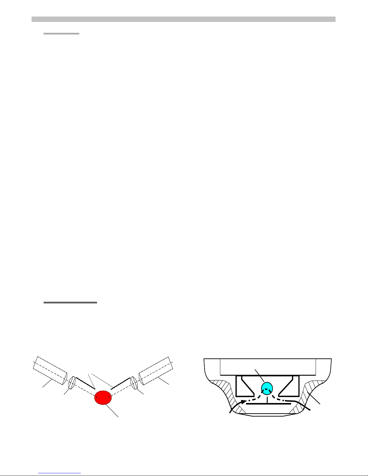
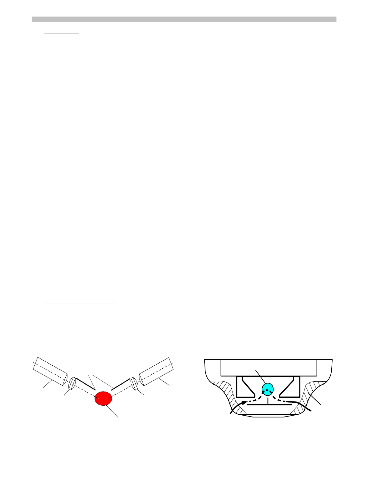
2.1 OPTICAL SYSTEM
The FC400PH detects visible particles produced in fires by using the light scatter-
ing properties of the particles. The detector uses the optical arrangement shown
diagrammatically in Fig.1. The optical system consists of an infra-red emitter and
receiver, with a lens in front of each, so arranged that their optical axes cross in the
sampling volume.The emitter, with its lens, produces a narrow beam of light which
is prevented from reaching the receiver by the baffles.When smoke is present in
the sampling volume a proportion of the light is scattered, some of which reaches
the receiver.For a given type of smoke, the light reaching the photodetector is pro-
portional to the smoke density.
2.2 FEATURES OF MEASURING CHAMBER
The FC400PH uses vertical chevrons to exclude ambient light..Smoke incident on
the detector is channelled into the detector by the outer cover fins (see Fig. 2) and
passes through the vertical chevrons.The smoke is deflected into the optical cham-
ber and through the sampling volume before passing out the other side of the detec-
tor. The emitter (see Fig. 1) is a GaAlAs solid state type operating in the near
infra-red (880nm peak), while the detector is a matched silicon photodiode.These
devices together with their associated lenses are held in place by the chamber
mouldings.The design of the optical system is such that the presence of small in-
sects such as thrips should not cause false alarms.
2.3 THERMAL MEASURING SYSTEM
The heat element of the detector uses a single thermistor to produce a linear out-
put dependent on absolute temperature. Rate of change of temperature is deter-
mined by the controller by using differences between consecutive temperature
values returned to the controller.
2.4 CIRCUIT DESCRIPTIONS
2.4.1 OPTICAL
The emitter is only pulsed every time the detector is polled from the controller, this
is to reduce quiescent current.The optical pulse signal as received by the
photodetector (a signal proportional to the scatter within the optical chamber) is fed
to the ‘Optical ASIC’.The optical ASIC amplifies the analogue signal which is fed to
an analogue input on the common circuit.
2.4.2 HEAT
A simplified block schematic of the circuit is given in Fig. 3.
The negative temperature coefficient thermistor produces a linear analogue output
which is fed to an analogue input on the common circuit.
1. INTRODUCTION
The FC400PH optical smoke and heat detector forms part of the FC400 Series of
Addressable Fire detectors.The detector is intended to plug into one of the following:
Ø5B 5” Universal Base
ØFC450IB 5” Isolator Base
Software within the controller is used to interpret the returned optical and heat val-
ues to raise alarm or other appropriate response according to the type of detector
configured in Fire Class 500 Console. The mode of detector may be:
§Mode 1 - Optical smoke only detector (sensitivity High, Normal or Low)
§Mode 2 - Optical (sensitivity High, Normal or Low) and heat fixed temperature
60oC (A2S)
§Mode 3 - Heat only rate-of-rise (A1R) detector (no sensitivity selection)
§Mode 4 - Heat fixed temperature 60oC (A2S) (no sensitivity selection)
§Mode 5 - Heat rate-of-rise (A1R) detector and optical smoke (sensitivity High,
Normal or Low)
§Mode 6 - HPO (Advanced) smoke detector (sensivity High, Normal or Low)
§Mode 7 - HPO (Advanced) and heat fixed temperature 60oC (A2S)
§Mode 8 - HPO (Advanced) and heat rate-of-rise (A1R)
☞Note:
ØThe heat detection grades are to EN54-5.
ØNormal and High sensitivity settings meetthe requirements of EN54-7.
1.1 DETECTION LOGIC
The optical smoke detector can be selected in one logic mode as follows:
1.1.1 NORMAL MODE
In the normal detection mode, an alarm is generated when an alarm threshold is
reached.
1.2 DAY/NIGHT SWITCHING
Two modes of detector operation are selectable from the list of possible modes as
follows:
Ø‘Normal’ mode, ie night time operation in which the detector will be evaluated
most of the time.
Ø‘Day’ mode in which the detector can be switched under certain circumstances,
eg during daytime when the building is occupied with people being able to de-
tect a fire manually. Switching to the ‘daytime’ mode can be done either by user
action (pressing the DAY/NIGHT switch on the controller), event or time driven.
1.3 SENSITIVITY SWITCHING
In addition to mode switching, the sensitivity can be changed within the actual
mode.This can be done either by user action or be event or time driven (eg,
day/night switching). Changing the sensitivity is done by shifting the sensitivity by
one level up or down.
2. OPERATING PRINCIPLE
The FC400PH operates by sensing the optical scatter from smoke particles gener-
ated in a fire.While the optical scatter detector can give good detection perfor-
mance for the majority of fires, some fast burning fires produce little visible smoke
and some produce very black smoke, neither of which are easily detected by the
optical scatter detector. (Such fires are represented in EN54-7 by Polyurethane
ENGLISH
EMETTITORE
EMITTER
LENTE
LENS
VOLUME DI CAMPIONAMENTO
SAMPLING VOLUME
LENTE
LENS
ELEMENTO FOTOSENSIBILE
PHOTO DETECTOR
SCHERMI
BAFFLES
FIG.1 Optical Chamber Schematic
PERCORSO DEL FUMO
SMOKE PATH
VOLUME DI CAMPIONAMENTO
SAMPLING VOLUME
ALETTE
FINS
FIG.2 Measuring Chamber Showing Smoke Flow Path

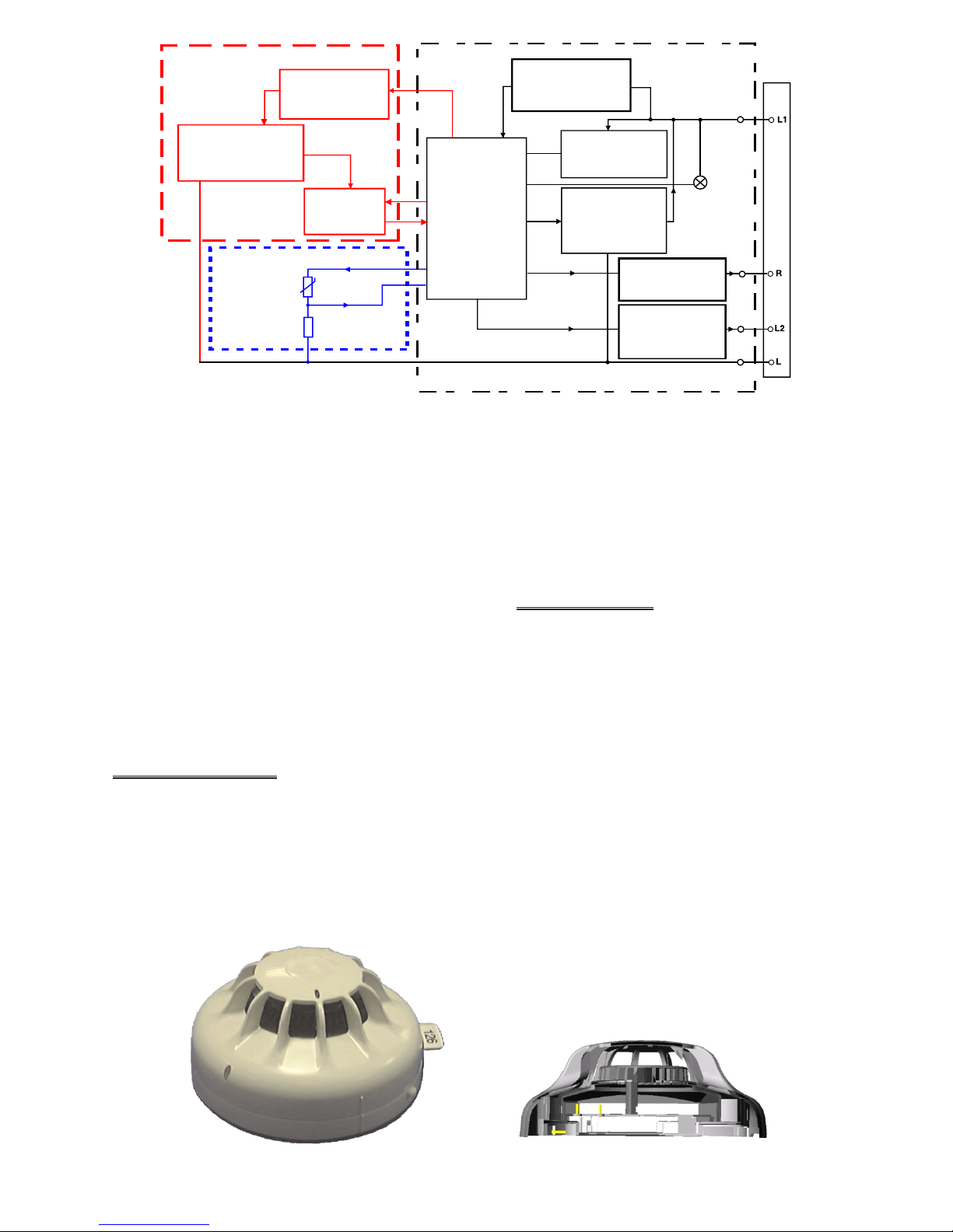
2.4.3 COMMON CIRCUIT
Refer to Fig. 3.
Communications between the controller and detector uses the Frequency Shift
Keying (FSK) method. The ‘Discrimination Circuit’ filters the FSK signal from the
L1 (+ve) line voltage and converts it to a digital square wave input for the ‘Commu-
nications ASIC’.The ‘Communications ASIC’ decodes the signal and when its own
address is decoded, the analogue inputs received from the optical and heat sens-
ing elements are converted to corresponding digital values. These digital values
are then passed to the ‘Tx Driver Circuit/Current Sink’ which applies them to the L1
(+ve) line for transmission to the controller. The Common Circuit is also used to:
ØControl Sounder and Relay bases via the ‘Functional Base Interface Circuit’
from controller commands.
ØControl the operation of the Remote LED via the ‘Remote LED Circuit’ from con-
troller commands.
2.5 WIRING
Loop cabling is connected to base terminals L (-ve) and L1 (+ve). A drive is pro-
vided for a remote indicator connected between loop positive and terminal R. Ter-
minal L2 (analogue output) is for use with functional sounder and relay bases.
3. MECHANICAL CONSTRUCTION
The major components of the detector are:
ØBody Assembly
ØPrinted Circuit
ØOptical Chamber
ØOptical Chamber Cover
ØThermistor
ØLight Pipe
ØOuter Cover
3.1 ASSEMBLY
The body assembly consists of a plastic moulding which has four embedded de-
tector contacts which align with contacts in the base.The moulding incorporates
securing features to retain the detector in the base. The PCB is clipped to the body
by four spring contacts.These contacts act as a mechanical fixture during assem-
bly and provide electrical contact between the contacts and the PCB. The chamber
cover is clipped to the body over the optical chamber ensuring the thermistor pro-
trudes through the cover.The light pipe is slotted into the chamber cover.Finally,
the outer cover is clipped to the body.
4. TECHNICAL SPECIFICATION
4.1 MECHANICAL
Dimensions: The overall dimensions are shown in
Fig.5 ( less base ).
Materials
Body,cover, and closure: FR110 ‘BAYBLEND’ flame retardant.
Weight
Detector: 0.076kg
Detector + Base: 0.14kg
4.2 ENVIRONMENTAL
Temperature
Operating: -25oC to +70oC
Storage: -40oC to +80oC
Relative Humidity: 95% ( non-condensing )
Shock:
Vibration: EN54-5 and EN54-7
Impact:
Corrosion: EN54-5 and EN54-7
The detectors comply with Lloyd’s Register Test Specification Number 1 (1996).
Environmental Category ENV5.
FIG.4 Sectioned and Top View of the Detector
INTERFACCIA
COMUNICAZIONE ASIC
COMMUNICATIONS
ASIC INTERFACE
LOGICA SET/LATCH
DI ELABORAZIONE
DELL’INDIRIZZO
ADDRESS SET/LATCH
SIGNAL PROCESSING
LOGIC
CIRCUITO COMUNE
COMMON CIRCUIT
ELEMENTO FOTOSENSIBILE
OPTICAL ELEMENT
CIRCUITO SENSORE OTTICO
OPTICAL SENSING CIRCUIT
CIRCUITO TEST AUTOMATICO
CIRCUIT SELF TEST
ASIC OTTICO
OPTICAL ASIC
STABILIZZATORE DI TENSIONE
VOLTAGE REGULATOR
CIRCUITO DISCRIMINATORE
DISCRIMINATION CIRCUIT
FSKIN
FSKOUT
CIRCUITO Tx DRIVER/
ASSORBIMENTO CORRENTE
Tx DRIVER CIRCUIT/
CURRENT SINK
LED ALLARME
ALARM LED
-VE LINEA IN/OUT
-VE LINE IN/OUT
+VE LINEA IN/OUT
+VE LINE IN/OUT
BASE
BASE
CIRCUITO LED REMOTO
REMOTE LED CIRCUIT
CIRCUITO D’INTERFACCIA
DELLA BASE FUNZIONALE
FUNCTIONAL BASE
INTERFACE CIRCUIT
ELEMENTO TERMOSENSIBILE
HEAT ELEMENT
FIG.3 Simplified Block Schematic of detector

4.3 ELECTROMAGNETIC COMPATIBILITY
The detector complies with the following:
ØProduct family standard EN50130-4 in respect of Conducted Disturbances, Radi-
ated Immunity, Electrostatic Discharge, Fast Transients and Slow High Energy;
ØEN61000-6-3 for Emissions.
4.4 ELECTRICAL CHARACTERISTICS
The following characteristics (Table 1) apply at 25oC and nominal supply voltage of
37.5V unless otherwise specified.
Table 1: Electrical Characteristics
Characteristic Min. Typ. Max. Unit
Loop Voltage 20.0 - 40 V
Quiescent Current - 275 305 μA
Alarm Current* 3 3.3 mA
* No remote indicator fitted
4.5 PERFORMANCE CHARACTERISTICS
The FC400PH detector, with its base, forms an addressable detector which trans-
mits signals representing the detector digital current levels to a remote control unit.
The control unit evaluates these signals against pre-determined criteria and de-
cides when an alarm condition has occurred.The information given below there-
fore relates to the performance of the FC400PH as a transducer only, since the
system alarm response is determined by the control unit.
4.5.1 RESPONSE TO SMOKE
The response of an optical smoke detector is normally measured with reference to
the obscuration produced by smoke.Obscuration is measured in percent per
metre, or in dB per metre.The latter unit is used in EN54-7 and is designated ‘m’.
Unfortunately, there is no fixed relationship between optical scattering and
obscuration, the ratio between them being dependent on the type of smoke. For
convenience, ‘grey’ smoke is normally used but white and black smokes give more
or less scattered light respectively for a given obscuration level. The working of the
FC400PH is a linear function of obscuration for a given type of smoke as shown
graphically in Fig. 6.
4.5.2 RESPONSE TO RATE OF CHANGE OF TEMPERATURE (HPO)
The detector will not be enhanced by slow rates of change of temperature or nega-
tive rates of change of temperature. The detector is designed to detect sudden hor-
izontal draughts of hot air produced by fast burning fires. The enhancement
switching point has been set to allow the detection of TF1 type fires.
5. DETECTOR ADDRESS
The loop address of the detector is held in internal E2PROM which is pro-
grammed from the FC490ST Address Programmer.
☞Note: this device use one address only on the loop.
6. ADDRESS FLAG
Refer to Fig.7. The address flag is used to identify the address and zone of the
detector.The address flags are supplied in a packs (address 1 - 255, with a differ-
ent colour for each loop) and are ordered separately from the detector.The ad-
dress flag is fitted to the bottom of the detector. When the detector is fitted to the
base and turned until fully located the address flag is then transferred to the
base. If the detector is removed from the base, the address flag remains with the
base.
7. ORDERING INFORMATION
FC400PH Optical Smoke + Heat detector.
5B 5” Universal Base.
FC450IB 5” Isolator Base.
FIG.5 Overall Dimensions of FC400PH detector
OSCURAMENTO : m-VALORE
OBSCURATION : m-VALUE
FUNZIONAMENTO DELL’USCITA (BITS)
WORKING OUTPUT (BITS)
FIG.6 Graph
INCAVI DI BLOCCAGGIO
RETAINING DEPRESSIONS
RIENTRANZA DI MONTAGGIO
MOUNTING RECESS
PARTE SAGOMATA A ´D`
´D` SHAPED PART
CANALE SAGOMATO A ´U`
´U` SHAPED CHANNEL
SPORGENZE DI BLOCCAGGIO
RETAINING PIMPLES
FIG.7 Fitting Address Label Carrier

8. RECYCLING INFORMATION
Customers are recommended to dispose of their used equipments (panels, detec-
tors, sirens, and other devices) in an environmentally sound manner. Potential
methods include reuse of parts or whole products and recycling of products, com-
ponents, and/or materials.
9. WASTE ELECTRICAL AND ELECTRONIC EQUIPMENT (WEEE)
DIRECTIVE
In the European Union, this label indicates that this product should
NOT be disposed of with household waste. It should be deposited at
an appropriate facility to enable recovery and recycling.
The manufacturer reserves the right to change the technical specifications of this
product without prior notice.
nella norma EN54-7 rispettivamente da incendi tipo Poliuretano e Eptano). Questi incen-
di producono un'elevata emissione di calore con un innalzamento della temperatura del-
l'aria. Il rilevatore è stato progettato per fornire una migliore rilevazione di tali incendi,
analizzando il rapido tasso di aumento della temperatura dell'aria ed incrementando, in
queste circostanze, la sensibilità di rilevazione fumo.Questo permette un'individuazione
tempestiva di tali incendi e maggiori possibilità di rilevazione rispetto ad un rilevatore
standard. Il rilevatore FC400PH possiede i seguenti due sistemi di rilevazione:
ØUna camera ottica con un'elettronica collegata, per misurare la presenza di
fumo dalla diffusione della luce.
ØUn termistore con la relativa elettronica collegata per rilevare la presenza di cor-
renti di aria calda o temperature elevate.
2.1 SISTEMA OTTICO
L'art. FC400PH rileva le particelle visibili prodotte negli incendi usando le proprietà di
diffusione della luce delle particelle. Il sistema ottico usato dal rilevatore è visualizza-
to nello schema in Fig.1. Il sistema ottico è composto da un emettitore e da un ricevi-
tore infrarosso, entrambi hanno delle lenti sistemate frontalmente in maniera che il
loro asse ottico attraversi il volume di campionamento. L'emettitore,con la relativa
lente, produce uno stretto fascio luminoso che non può raggiungere il ricevitore a
causa degli schermi. Quando del fumo è presente nel volume di campionamento
parte della luce si diffonde raggiungendo il ricevitore. Per un dato tipo di fumo, la luce
che raggiunge l'elemento fotosensibile è proporzionale alla densità del fumo.
2.2 CARATTERISTICHE DELLA CAMERA DI ANALISI
L'art.FC400PH usa una particolare copertura per escludere la luce ambientale. Il fumo
incidente sul rilevatore è incanalato all'interno dello stesso dalle alette della copertura
esterna (vedere Fig.2) e dai passaggi attraverso il profilo sagomato. Il fumo deviato al-
l'interno della camera ottica, attraversa il volume di campionamento per poi andare
verso l'uscita dall'altro lato del rilevatore. L'emettitore (vedere Fig.1) è di tipo solido
GaAIAs con funzionamento vicino all'infrarosso (picco di 880 nm), mentre il rilevatore è
un fotodiodo al silicio. Questi dispositivi insieme alle loro lenti collegate sono tenuti in-
sieme dalla profilatura della camera. Il progetto del sistema ottico è tale che, la presen-
za di piccoli insetti, quali i tripidi, non deve causare falsi allarmi.
2.3 SISTEMA DI MISURA TERMICO
L'elemento termosensibile del rilevatore usa un singolo termistore per produrre
un'uscita lineare dipendente dalla temperatura assoluta. Il tasso di variazione della
temperatura è determinato dalla centrale utilizzando le differenze fra i valori con-
secutivi di temperatura restituiti alla centrale.
2.4 DESCRIZIONE DEL CIRCUITO
2.4.1 OTTICO
L'emettitore genera impulsi ogni volta che il rilevatore è attivato dalla centrale, que-
sto riduce la corrente di riposo. L'impulso ottico del segnale ricevuto dall'elemento
fotosensibile (un segnale proporzionale alla diffusione all'interno della camera otti-
ca) è alimentato dall ‘ASIC Ottico’. L'ASIC ottico amplifica il segnale analogico ali-
mentato da un'entrata analogica del circuito comune.
2.4.2 TERMICO
Uno schema a blocchi semplificato del circuito è visibile in Fig.3.
Il coefficiente negativo di temperatura del termistore produce un'uscita analogica
lineare alimentata da un ingresso analogico sul circuito comune.
1. INTRODUZIONE
Il rilevatore ottico di fumo e termico FC400PH fà parte della serie di rilevatori incen-
dio indirizzabili FC400. Il rilevatore è progettato per l'inserimento di quanto segue:
Ø5B 5” Base Universale
ØFC450IB 5” Base con Isolatore
Il software all'interno della centrale è usato per interpretare i valori ottico e termico in arri-
vo e attivare l'allarme o un altro tipo di azione secondo la tipologia del rilevatore configura-
to nella Fire Class 500 Console. I modi di funzionamento del rilevatore possono essere:
§Modo 1 - Rilevatore solo ottico di fumo (sensibilità Alta, Normale o Bassa)
§Modo 2 - Ottico (sensibilità Alta, Normale o Bassa) e termico temperatura fissa
di 60oC (A2S)
§Modo 3 - Rilevatore solo a gradiente di temperatura (A1R) (senza selezione sensibilità)
§Modo 4 - Temperatura fissa di 60oC (A2S) (senza selezione di sensibilità)
§Modo 5 - Rilevatore a gradiente di temperatura (A1R) e ottico di fumo (sensibili-
tà Alta, Normale o Bassa)
§Modo 6 - Rilevatore di fumo HPO (Avanzata) (sensibilità Alta, Normale o Bassa)
§Modo 7 - HPO (Avanzata) e termico temperatura fissa 60°C (A2S)
§Modo 8 - HPO (Avanzata) e termico a gradiente di temperatura (A1R)
☞Note:
ØLe classi di rilevazione termica rispondono ai requisiti EN54-5.
ØLe regolazioni normali e ad alta sensibilità rispondono ai requisiti EN54-7.
1.1 LOGICA DEL RILEVATORE
Il rilevatore ottico di fumo può essere impostato nel modo logico seguente:
1.1.1 MODO NORMALE
Nel funzionamento in modo normale il rilevatore genera un allarme quando viene
raggiunta la soglia d'intervento.
1.2 COMMUTAZIONE GIORNO/NOTTE
Due modalità di funzionamento del rilevatore sono selezionabili dalla lista dei pos-
sibili modi operativi, come segue:
ØModo ‘Normale’, funzionamento notturno nel quale il rilevatore viene controllato
la maggior parte del tempo.
ØModo ‘Giorno’ sul quale il rilevatore può essere commutato se ci sono certe
condizioni, esempio durante l'arco del giorno quando l'edificio è occupato da
persone che possono attivare manualmente la rilevazione incendio. La com-
mutazione nel modo ‘giorno’ può essere effettuata tramite un'azione dell'utente
(attivando l'interruttore GIORNO/NOTTE sulla centrale), evento o periodico.
1.3 COMMUTAZIONE DELLA SENSIBILITÀ
In aggiunta al modo di commutazione, la sensibilità può essere cambiata all'inter-
no del modo effettivo. Ciò può essere fatto da un'azione dell'utente per evento op-
pure periodico (esempio,commutazione giorno/notte). Il cambio della sensibilità
viene fatto spostando il livello di uno verso l'alto o verso il basso.
2. PRINCIPIO DI FUNZIONAMENTO
L'art. FC400P funziona percependo, tramite un sensore ottico, l'espandersi delle parti-
celle di fumo generate in un incendio. Mentre la diffusione ottica del rilevatore dà buone
prestazioni di rilevazione per la maggior parte degli incendi, in alcuni incendi rapidi dove il
fumo prodotto è poco visibile, oppure il fumo è molto scuro, la rilevazione, da parte del ri-
levatore di diffusione ottica, non è assolutamente facile. (Tali incendi sono rappresentati
ITALIANO
EMETTITORE
EMITTER
LENTE
LENS
VOLUME DI CAMPIONAMENTO
SAMPLING VOLUME
LENTE
LENS
ELEMENTO FOTOSENSIBILE
PHOTO DETECTOR
SCHERMI
BAFFLES
Schema Camera OtticaFIG.1
PERCORSO DEL FUMO
SMOKE PATH
VOLUME DI CAMPIONAMENTO
SAMPLING VOLUME
ALETTE
FINS
Camera di misurazione con il percorso di flusso del fumoFIG.2
2.4.3 CIRCUITO COMUNE
Vedere Fig.3.
Le comunicazioni tra la centrale ed il rilevatore usano il metodo di modulazione in fre-
quenza (FSK). Il ‘Circuito Discriminatore’ filtra il segnale FSK dalla linea di tensione
L1 (+ve) e lo converte in forma d'onda quadra digitale utilizzata per la ‘Communica-
zione ASIC’. La ‘Communicazione ASIC’ decodifica il segnale e quando l'indirizzo è
decodificato le entrate analogiche ricevute dagli elementi di rilevazione ottica e ter-
mica sono convertite in corrispondenti valori digitali. Questi valori digitali vengono
passati al ‘Circuito Tx Driver /Assorbimento corrente’ che li applica alla linea L1 (+ve)
per la trasmissione alla centrale. Sul Circuito Comune è inoltre utilizzato:
ØContollo delle basi acustiche e relè tramite ‘Circuito d'Interfaccia della Base
Funzionale’ dai comandi della centrale.
ØControllo del funzionamento del LED Remoto tramite ‘Circuito LED Remoto’ dai
comandi della centrale.
2.5 COLLEGAMENTO
Il collegamento al loop è realizzato sui terminali base L (-ve) e L1 (+ve). Un azio-
namento è fornito per un indicatore remoto collegato tra il positivo del loop ed il
terminale R. Il terminale L2 (uscita analogica) è utilizzato con le basi acustica
funzionale e relè.
3. COSTRUZIONE MECCANICA
I maggiori componenti del rilevatore sono:
ØCorpo Assemblato
ØCircuito Stampato
ØCamera Ottica
ØCoperchio Camera Ottica
ØTermistore
ØCondotto Ottico
ØCoperchio Esterno
3.1 ASSEMBLAGGIO
Il corpo assemblato è costituito da un stampo in materiale plastico con quattro contatti
inseriti nel rilevatore allineati con i contatti della base. Lo stampaggio unisce e assicura
il mantenimento del rilevatore nella base. Il PCB è agganciato al corpo tramite quattro
contatti a molla. Questi contatti fungono da fissaggio meccanico durante l'assemblag-
gio stabilendo un contatto elettrico tra i contatti ed il PCB. Il coperchio della camera è
agganciato al corpo sopra la camera ottica assicurando il termistore il quale sporge at-
traverso il coperchio. Il condotto ottico è composto da una scanalatura all'interno del
coperchio della camera. Infine, il coperchio esterno è agganciato sul corpo.
4. SPECIFICHE TECNICHE
4.1 MECCANICHE
Dimensioni: Le dimensioni generali sono indicate in
Fig.5 (senza la base).
Materiali
Corpo,coperchio e chiusura: FR110 ‘BAYBLEND’ ritardante fiamma.
Peso
Rilevatore:0,076 Kg
Rilevatore + Base: 0,14 Kg
4.2 CARATTERISTICHE AMBIENTALI
Temperatura
Funzionamento: da -25 a +70oC
Stoccaggio: da -40 a +80oC
Umidità relativa:95% ( senza condensa )
Shock:
Vibrazione: EN54-5 e EN54-7
Impatto:
Corrosione: EN54-5 e EN54-7
I rilevatori sono conformi alla Specifica Numero 1 (1996) del Registro Test Lloyd’s.
Categoria Ambientale ENV5.
INTERFACCIA
COMUNICAZIONE ASIC
COMMUNICATIONS
ASIC INTERFACE
LOGICA SET/LATCH
DI ELABORAZIONE
DELL’INDIRIZZO
ADDRESS SET/LATCH
SIGNAL PROCESSING
LOGIC
CIRCUITO COMUNE
COMMON CIRCUIT
ELEMENTO FOTOSENSIBILE
OPTICAL ELEMENT
CIRCUITO SENSORE OTTICO
OPTICAL SENSING CIRCUIT
CIRCUITO TEST AUTOMATICO
CIRCUIT SELF TEST
ASIC OTTICO
OPTICAL ASIC
STABILIZZATORE DI TENSIONE
VOLTAGE REGULATOR
CIRCUITO DISCRIMINATORE
DISCRIMINATION CIRCUIT
FSKIN
FSKOUT
CIRCUITO Tx DRIVER/
ASSORBIMENTO CORRENTE
Tx DRIVER CIRCUIT/
CURRENT SINK
LED ALLARME
ALARM LED
-VE LINEA IN/OUT
-VE LINE IN/OUT
+VE LINEA IN/OUT
+VE LINE IN/OUT
BASE
BASE
CIRCUITO LED REMOTO
REMOTE LED CIRCUIT
CIRCUITO D’INTERFACCIA
DELLA BASE FUNZIONALE
FUNCTIONAL BASE
INTERFACE CIRCUIT
ELEMENTO TERMOSENSIBILE
HEAT ELEMENT
Schema a blocchi semplificato del rilevatoreFIG.3
Sezione e vista superiore del rilevatoreFIG.4

4.3 COMPATIBILITÀ ELETTROMAGNETICA
Il rilevatore è conforme a quanto segue:
Øfamiglia di prodotto standard EN50130-4 rispetto alle Perturbazioni Dirette,
Immunità Irradiata, Scarica Elettrostatica, Transitori Rapidi e Alta Energia Lenta;
ØEN 61000-6-3 per le Emissioni.
4.4 CARATTERISTICHE ELETTRICHE
Le seguenti caratteristiche (Tabella 1) si applicano alla temperatura di 25oC e alla
tensione nominale di alimentazione di 37,5 V salvo diverse specifiche.
Tabella 1: Caratteristiche elettriche
Caratteristica Min. Tip. Mass. Unità
Tensione Loop 20,0 - 40 V
Corrente a Riposo - 275 305 μA
Corrente in Allarme* 3 3.3 mA
*Senza indicatore remoto
4.5 CARATTERISTICHE DELLE PRESTAZIONI
Il rilevatore FC400PH, con la base, forma un rilevatore indirizzabile il quale trasmette i
segnali che rappresentano i livelli digitali correnti alla centrale di controllo. La centrale
di controllo valuta e confronta questi segnali con i criteri di taratura e decide quando si
verifica una condizione d'allarme. Le informazioni fornite di seguito si riferiscono quindi
alle prestazioni dell'art.FC400PH soltanto come trasduttore, poichè la risposta del si-
stema d'allarme è determinata dalla centrale di controllo.
4.5.1 RISPOSTA AL FUMO
La risposta di un rilevatore ottico di fumo è normalmente misurata in riferimento al-
l'oscuramento prodotto dal fumo. L'oscuramento è misurato in percentuale per
metro, o in dB per metro. La seconda unità è usata nella norma EN54-7 ed è indi-
cata con ‘m’. Purtroppo non sussiste una relazione fissa tra la diffusione ottica e
l'oscuramento, il rapporto tra loro dipende dal tipo di fumo. Per convenzione viene
normalmente considerato il fumo ‘grigio’, ma il fumo bianco o scuro dà rispettiva-
mente più o meno luce diffusa per un dato livello di oscuramento. Il funzionamento
dell'art. FC400PH dipende in maniera lineare dall'oscuramento per un dato tipo di
fumo, come visibile sul grafico in Fig.6.
4.5.2 RISPOSTA AL TASSO DI VARIAZIONE DELLA TEMPERATURA (HPO)
Il rilevatore non può essere efficace per lenti gradienti di variazione della tempera-
tura o per gradienti negativi di variazione della temperatura. Il rilevatore è progetta-
to per rilevare le correnti orizzontali improvvise d'aria calda prodotte dai fuochi a
propagazione rapida. L'aumento del punto della commutazione è stato regolato
per permettere di rilevare i fuochi di prova TF1.
5. INDIRIZZO DEL RILEVATORE
L'indirizzo di loop del rilevatore è inserito all'interno della E2PROM ed è program-
mato dallo strumento di programmazione dispositivi indirizzabili FC490ST.
☞Nota: questo dispositivo impegna un solo indirizzo del loop.
6. LINGUETTA INDIRIZZO
Vedere Fig.7. La linguetta indirizzo è usata per identificare l'indirizzo e la zona del rileva-
tore. La linguetta indirizzo è fornita in confezioni (indirizzi 1-255, con un differente colore
per ogni loop) ed è ordinabile separatamente dal rilevatore. La linguetta indirizzo è in do-
tazione con la parte inferiore del rilevatore. Quando il rilevatore è posizionato sulla base e
ruotato fino al collocamento, la linguetta indirizzo và trasferita sulla base.Se il rilevatore
viene rimosso dalla base, la linguetta indirizzo rimane sulla base.
7. INFORMAZIONI PER L'ORDINE
FC400PH Ottico di fumo + Rilevatore di Temperatura.
5B 5” Base Universale.
FC450IB 5” Base con Isolatore.
8. INFORMAZIONI SUL RICICLAGGIO
Si consiglia ai clienti di smaltire i dispositivi usati (centrali, rilevatori, sirene, accessori
elettronici, ecc.) nel rispetto dell'ambiente. Metodi potenziali comprendono il riutilizzo di
parti o di prodotti interi e il riciclaggio di prodotti, componenti e/o materiali.
9. DIRETTIVA RIFIUTI DI APPARECCHIATURE ELETTRICHE ED
ELETTRONICHE (RAEE - WEEE)
Nell'Unione Europea, questa etichetta indica che questo prodotto
NON deve essere smaltito insieme ai rifiuti domestici. Deve essere
depositato in un impianto adeguato che sia in grado di eseguire
operazioni di recupero e riciclaggio.
Il costruttore si riserva il diritto di modificare le specifiche tecniche di questo pro-
dotto senza preavviso.
Dimensioni generali del rilevatore FC400PHFIG.5
OSCURAMENTO : m-VALORE
OBSCURATION : m-VALUE
FUNZIONAMENTO DELL’USCITA (BITS)
WORKING OUTPUT (BITS)
GraficoFIG.6
INCAVI DI BLOCCAGGIO
RETAINING DEPRESSIONS
RIENTRANZA DI MONTAGGIO
MOUNTING RECESS
PARTE SAGOMATA A ´D`
´D` SHAPED PART
CANALE SAGOMATO A ´U`
´U` SHAPED CHANNEL
SPORGENZE DI BLOCCAGGIO
RETAINING PIMPLES
Inserimento della linguetta indirizzoFIG.7
Table of contents
Languages:
Other Bentel Smoke Alarm manuals

Popular Smoke Alarm manuals by other brands


Smartwares
Smartwares RM218 manual

Red Smoke Alarms
Red Smoke Alarms R9 installation instructions

First Alert
First Alert FA2000C Installation and setup guide

Teknim
Teknim TFD 1430 Installation and user manual

Convoy Security
Convoy Security YT202 Installation and maintenance instructions

BRK electronic
BRK electronic First Alert P1010 quick start guide