Bently Nevada 19045 User manual

Part Number TW8029303
Rev. D (08/07)
Bently Nevada™ Asset Condition Monitoring
Installation Manual
DC-LVDT/Housing Assembly
Model 19045, 19046, 19047

DC-LVDT/Housing Assembly Model 19045, 19046, 19047 Installation Manual
ii
Copyright 1978. Bently Nevada LLC.
All rights reserved.
The information contained in this document is subject to change without notice.
Contact Information
The following ways of contacting Bently Nevada are provided for those times when you
cannot contact your local representative:
Mailing Address 1631 Bently Parkway South
Minden, Nevada USA 89423
USA
Telephone 1.775.782.3611
1.800.227.5514
Fax 1.775.215.2873
Internet www.ge-energy.com/bently

iii
Additional Information
Product Disposal Statement
Customers and third parties, who are not member states of the European Union, who are
in control of the product at the end of its life or at the end of its use, are solely
responsible for the proper disposal of the product. No person, firm, corporation,
association or agency that is in control of product shall dispose of it in a manner that is
in violation of any applicable federal, state, local or international law. Bently Nevada LLC
is not responsible for the disposal of the product at the end of its life or at the end of its
use.

DC-LVDT/Housing Assembly Model 19045, 19046, 19047 Installation Manual
iv
Contents
1. DESCRIPTION ...................................................................................................1
2. INSTALLATION .................................................................................................5
3. MAINTENANCE ..............................................................................................11
4. RECOMMENDED SPARE PARTS ...................................................................12
5. APPENDIX - SPECIFICATIONS ......................................................................13

Section 1 - DESCRIPTION
1
1. DESCRIPTION
GENERAL
The DC-LVDT (LVDT) transducer used with Bently Nevada Corporation (BNC)
instruments provides a linear dc output voltage over a specific range of core
movement. This output, connected to the BNC Case Expansion Indicator, is used
to measure the expansion of a machine case as operating conditions vary. The
LVDT is connected mechanically between a reference point on the machine
foundation and a point on the machine that exhibits the measured expansion.
Input power to the LVDT is supplied from the BNC instrument to which it is
connected. Circuitry within the LVDT body converts the machine expansion
measurement (core position) to the required output signal. The BNC instrument
accepts the signal and produces a meter indication of expansion measurement.

DC-LVDT/Housing Assembly Model 19045, 19046, 19047 Installation Manual
2
LVDT HOUSING ASSEMBLY OPTIONS
Table 1-1. LVDT Housing Options
CATALOG NO ASSEMBLY
19045 - AXX
01 DC-LVDT Housing Assembly with Model 500
HR-DC LVDT
02 DC-LVDT Housing Assembly with Model
1000 HR-DC LVDT
19046 – AXX
01 DC-LVDT Housing Assembly with Model
2000 HR-DC LVDT
02 DC-LVDT Housing Assembly with Model
2000 HR-DC LVDT
19047 – AXX
01 DC-LVDT Housing Assembly with Model 2000 HR-DC
LVDT @ 9.25 in. span, max*
02 DC-LVDT Housing Assembly with Model 2000 HR-DC
LVDT @ 12.00 in. span, max*
*19047-01 option can span up to 9.25 inches maximum, the -02 option can span
up to 12.00 inches. Total travel (range), however, is determined by the position of
the riders on the slide bar. (See table in Figure A-4.)

Section 1 - DESCRIPTION
3
FUNCTIONAL DESCRIPTION
A functional block diagram of the LVDT internal circuitry is shown in Figure 1-1.
The 24 Vdc supply power is connected to LVDT lead wires. This voltage drives an
oscillator to produce an alternating current. The alternating current is applied to
the primary of the differential transformer. The transformer has two secondary
windings, 180° out of phase, that are coupled to the primary by the movable core.
Core position determines the output voltage amplitude of each secondary. The
secondary outputs are applied to a demodulator which produces a dc voltage
signal. This signal varies in amplitude and polarity from negative, to zero (null), to
positive as the core moves through its operating range in a toward-LVDT
direction. Figure 1-2 is a graph of the output signal of the DC-LVDT models used
with BNC instruments. Output voltage is zero when the core and housing null
centers coincide.
Figure 1-1. DC-LVDT Functional Block Diagram

DC-LVDT/Housing Assembly Model 19045, 19046, 19047 Installation Manual
4
Figure 1-2. DC-LVDT Output versus Core Position

Section 2 - INSTALLATION
5
2. INSTALLATION
RECEIVING INSPECTION
Visually inspect exterior and interior to determine if any shipping damage has
occurred. (Figures A-2, A-3, and A-4 illustrate the fasteners that retain the housing
cover.)
If shipping damage is apparent, file a claim with the carrier and submit a copy to
BNC. The transducer housing assembly model number and appropriate option
numbers listed in Table 1-1 should be included with all correspondence. The user
will be advised concerning repair or replacement in accordance with the
guarantee.
OPERATING DIRECTION
Correct function of the LVDT instrument system requires that the transducer be
properly oriented to the measured machine movement according to the direction
option of the instrument; Toward-LVDT or Away-From-LVDT.
The direction option specifies the direction of LVDT core motion that produces
upscale meter movement at the instrument. Refer to the Option Table of the
instrument manual for the direction option. Figure 1-2 defines the toward-LVDT
direction; away-from-LVDT is opposite. Regardless of the instrument direction
option, core motion toward the LVDT produces a positive-going transducer
output signal.
DC-LVDT/Housing Assembly Model 19045, 19046, 19047 Installation Manual
6
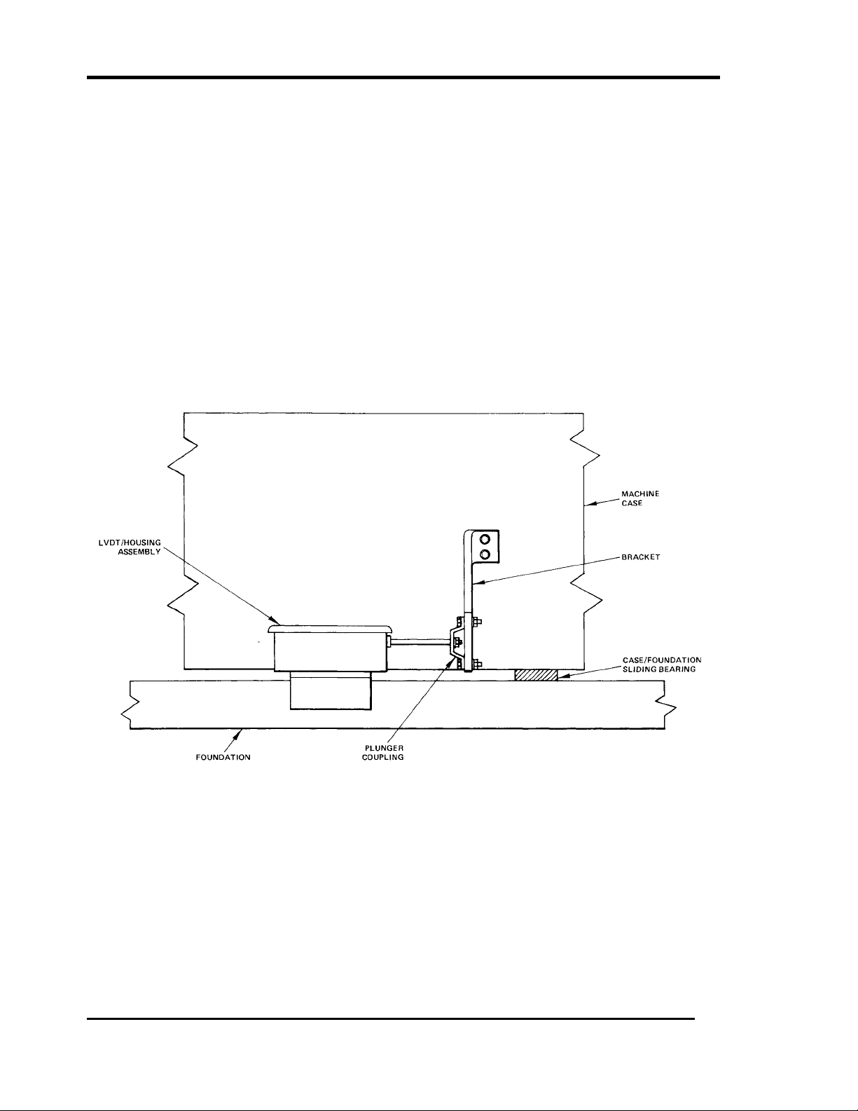
MECHANICAL LINKAGE
The maehine-LVDT linkage design is determined by the user. A typical case
expansion measurement linkage is illustrated in Figure 2-1. In general, linkage
design should conform to the following guidelines.
1. Linkage must not bind throughout the travel range.
2. Linkage weight must not be borne by the LVDT.
3. Adjustment provision is required to calibrate the LVDT output.
4. The LVDT plunger must be nonmagnetic material. (Series 300 nonmagnetic
stainless steel is used in the supplied plunger.) Magnetic material will
distort the LVDT output.
Figure 2-1. Typical CE Linkage

Section 2 - INSTALLATION
7
LVDT MOUNTING
Generally, configurations for the LVDT installations will vary; however, for all
installations, brackets or other structural members used to mount the LVDT
assembly must be rigid. If the bracket is flexible, undesireable relative motion
between the LVDT and observed machine part may result. Brackets must support
the LVDT so that the core axis aligns with the movement of connecting linkage.
Assembly installation is as follows.
a. Mount the LVDT housing to the designated mounting location. (Refer to
Figures A-2, A-3, and A-4, outline of LVDT housing assemblies, for
dimensions and component locations.) Housing mounting holes are
determined by the user.
b. Attach the connecting linkage between the machine and LVDT plunger.
Assure that linkage supports are properly aligned, linkage is free from
binding, and travel is unobstructed throughout the measurement range.
c. Check that the LVDT/housing assembly components are secure and housing
is free of foreign material. Final adjustment is performed after completing
electrical installation.
CAUTION
TO PREVENT LOSS OF MACHINE
PROTECTION, SECURE THE PUSH ROD
AND THE CORE PIN USING GLUE.
RECOMMENDED, LOCTITE
THREADLOCKER 242 (BNC PART NO,
04576130).

DC-LVDT/Housing Assembly Model 19045, 19046, 19047 Installation Manual
8
POWER AND SIGNAL CONNECTIONS
Connections between the LVDT and the instrument signal module are shown on
the interconnect diagram contained in the instrument manual. Cabling is
generally fabricated at the userTs facility, unless a specific request is made to
have BNC supply it. It is recommended that three-wire shielded cable be used for
these connections to avoid erroneous indications due to noise interference.
CAUTION
Be certain the transducer output and drive
voltage conductors do not become cross-
wired. An OK indication may be obtained, but
the equipment will not be operational.
Prolonged cross-wired connection can
change the output stage characteristics,
resulting in uncalibrated performance.
The COM connector at the transducer should not be used as the shield ground.
Ground the shield at the SHLD terminal of the signal module located in the
instrument rack. Grounding the shield at both ends is not recommended.
Precautions should be taken to keep electromagnetic interference away from the
cable by observing the following instructions.
1. Do not route transducer cables with power cables and other noise
sources.
2. Use steel conduit between the transducer and instrument rack assembly.

Section 2 - INSTALLATION
9
ADJUSTMENT
Adjustment requires measuring the LVDT output with the linkage set at the zero-
expansion point. Perform all adjustments as accurately as possible. The user may
construct a gaging tool, if desired, to aid in accurately adjusting the LVDT core
position during calibration. Table 2-1 lists recommended equipment for
adjustment. If LVDT power (-24 Vdc) is available from the instrument, the DC
Power Supply is not necessary.
LVDT linkage adjustment is performed in the following manner.
a. Disconnect the linkage at the machine case attaching point.
b. Supply the specified transducer power to the LVDT from the BNC instrument
or, if necessary, from the DC Power Supply. Check the voltage at the + and -
PWR terminals at the terminal block.
c. Connect the DMM to SIG and COM at the terminal block.
d. Manually adjust core position until the DMM displays 0.00 Vdc.
e. Move the LVDT core as follows:
If full scale expansion is toward-LVDT, move core away from the LVDT
exactly half the meter range of the indicator.
If full scale is away-from-LVDT, move core toward the LVDT exactly half the
meter range of the indicator.
The core is positioned for correct output signal at zero expansion of the
machine case. Mark or secure the core at this position.
f. Adjust the linkage carefully (with LVDT core at the zero-expansion position
set in step e) until the machine end of linkage is located at the zero-
expansion position of the attaching point on the machine case. Secure the
linkage adjustments.
g. Check the meter at the instrument to assure that linkage movement
produces the proper upscale/downscale meter response.
h. Connect the linkage to the machine case.

DC-LVDT/Housing Assembly Model 19045, 19046, 19047 Installation Manual
10
Table 2-1. Recommended Installation Equipment
RECOMMENDED EQUIPMENT EQUIPMENT SPECIFICATIONS
Hewlett-Packard HP970A 3-1/2 digit display with:
Digital Multimeter (DMM) 0 to ±1000 Vdc
0 to 1000 Vac
0 to 1000 mA dc
0 to 1000 mA ac
0 to 10 megohms
DC Power Supply 24 Vdc with less than
0.1% ripple and less than
3% regulation.

Section 3 - MAINTENANCE
11
3. MAINTENANCE
GENERAL
It is recommended that the user schedule inspections according to the
environment in which the transducer operates and the likelihood of wear or
damage.
TROUBLESHOOTING
The following troubleshooting procedure verifies proper LVDT performance. This
procedure should be followed in the order given.
a. Using the DMM, measure the voltage between the LVDT PWR ( + and - )
supply terminals at the housing terminal block. The DMM should
indicate between 22 and 26 volts. If the indication is not within this
range, the power supply from the instrument or associated wiring is
faulty. Restore power to the LVDT. If a proper voltage indication is
obtained, proceed to step b.
b. Disconnect the LVDT plunger from the linkage and manually position
the core to the null position. Refer to the Specifications and related
drawings for necessary dimensions.
c. Connect the DMM to the LVDT SIG and COM terminals. The voltage
shouldmeasure0Vdc±0.5 volt.
d. Measure the LVDT outputs with the core positioned at each extreme of
the measurement range that is specific to the LVDT model installed.
Move the core half the total range in each direction from the zero-
voltage core position. The voltages must correspond (within 5%) to the
scale factor listed for the specific LVDT in the manufacturers test data.
e. If the LVDT checks are satisfactory, check field wiring and, if necessary,
instrument performance.
PERIODIC INSPECTION
Linkage Integrity
Examine the linkage for looseness, misalignment, interference, corrosion, or other
detrimental conditions. Repair as necessary.
Mechanical Zero-Expansion Calibration
Check that placing the machine-to-LVDT linkage at the zero-expansion position
places the LVDT core at the correct point of travel. Refer to the Adjustment
paragraph in Section 2 for determining core position.

DC-LVDT/Housing Assembly Model 19045, 19046, 19047 Installation Manual
12
4. RECOMMENDED SPARE PARTS
Bently Nevada Corporation recommends that at least one of each type LVDT
transducer used in the instrument system be kept on hand as a spare. The
recommended spare parts for field maintenance are listed below. If the
instrument system is located in a remote area or is used on an extremely critical
application, several spares may be desired.
To order replacement units, specify the complete part number according to the
following table.
QTY*
PER LVDT
DESCRIPTION PART NUMBER
1DC-LVDT Housing Assembly See Table 1-1
1Model 500 HR-DC LVDT
Model 1000 HR-DC LVDT
Model 2000 HR-DC LVDT
00218500
00218501
00218502
*User option to stock either the Assembly or the LVDT only.

Section 5 - APPENDIX - SPECIFICATIONS
13
5. APPENDIX - SPECIFICATIONS
DC-LVDT TRANSDUCER
Input Power (nominal) -24 Vdc, 25 mA
Environmental Limits
Operation -18°C to +71°C
Storage -54°C to +93°C
Shock 250 g for 11 ms
Vibration 10 g @ 0 to 2 kHz
Construction
Body Series 400 magnetic stainless steel
Coil Laminated glass-epoxy
Lead Wire 24-gage stranded copper, Teflon insulated,
12 inches (31 mm)
Output
Ripple Less than 1% full scale
Linearity ±0.5% full range
Stability 0.125% full scale
Scale Factor
Temp. Coefficient 0.07%/°C

DC-LVDT/Housing Assembly Model 19045, 19046, 19047 Installation Manual
14
MODEL
500 HR-DC 1000 HR-DC 2000 HR-DC
Output
Scale Factor (nominal)
V/in (V/mm) 8.8 (0.35) 10.2 (0.40) 3.6 (0.14)
Linear Range ± 0.5 ± 1.0 ± 2.0
inches (mm) (±12.5) (±25.4) (±51)
-3 dB Frequency
(core movement) 20 Hz 15 Hz 10 Hz
Output Impedance
(nominal) 7 k ohm 7 k ohm 7 k ohm
Min Load Resistance 50 k ohm 100 k ohm 200 k ohm
Physical (See Figure A-l)
Body Length (A) 6.75 (171) 8.1 (206) 11.5 (292)
Body Diameter (B) 0.812 (20.6)
Body End to
NuU Center (C) 2.73 (69.3) 3.41 (86.6) 4.99 (126.7)
Core Length (D) 3.15 (80) 4.25 (108) 5.30 (135)
Core Diameter (E) 0.25 (6.4)
Plunger Length As required for application
Diameter 0.25 (6.4)
Thread 6-40 NF core end; 6-32 linkage end.
Material 300 Series nonmagnetic stainless steel.
HOUSING (19045, 19046, 19047) ASSEMBLIES
Dimensions/Construction See Figures A-2, A-3, and A-4.
Design Specification NEMA 3
Mounting Fastener Locations Optional per customer requirements.

Section 5 - APPENDIX - SPECIFICATIONS
15
Figure A-l. DC-LVDT Dimension Identification

DC-LVDT/Housing Assembly Model 19045, 19046, 19047 Installation Manual
16
This manual suits for next models
3
Table of contents
Other Bently Nevada Recording Equipment manuals


