BENY BCP Series User manual

WWW.BENY.COM
ZHEJIANG BENYI NEW ENERGY CO.,LTD.
WENZHOU BRIDGE INDUSTRIAL ZONE,BEIBAIXIANG TOWN, ZHEJIANG, CHINA
TEL: +86-577-5717 7008 FAX: +86-577-5717 7007
VERSION: 20230201
benyi@zjbeny.com
www.beny.com
This catalogue has been printed on ecological paper.
Zhejiang Benyi New Energy Co.,Ltd.all rights reserved.
If the models and specification in this product catalogue is changed due to the change of products, we wil not inform.
BCP Series
AC EV Charger
Use and lnstallation Manual
Scan For
More Information

CONTENTS
Operating status
Power on checking
Button
LED lights instructions
Buzzer prompt description
Start to use? Download the APP here
●
●
P-17
P-17
P-18
P-22
P-22
Prepare for installation
Minimum installation requirements
Position
Height
Maximize Wi-Fi signal reception(for models with Wi-Fi function)
Power supply
Installation considerations
●
●
●
●
●
P-05
P-06
P-06
P-06
P-07
P-08
●
Safety information
Important safety instructions
Cautions
Notes
Specification
Power Comparison Table
Features
●
●
●
●
●
P-01
P-02
P-02
P-03
P-03
P-04
In the box
In the box
●P-09
Installation instructions
Step-by-step installation instructions (bottom entry wiring)
Step-by-step installation instructions (top entry wiring)
Step-by-step installation instructions (rear entry wiring)
Set the operating current
Reinstall the sealing cover and turn on power
●
●
●
●
P-10
P-12
P-14
P-16
P-16
●
●
●
●
●
Maintenance instructions
Product overhaul
Warranty description
Safety notice
Operation and maintenance risk notification
Use risk notification
●
●
●
●
P-23
P-23
P-24
P-24
DLB Installation instructions
1 Phase Grid
Phase Grid 2
3 Phase Grid
Live wire 1 earth2 wire power supply method
●
●
●
●
P-25
P-26
P-27
P-28

Safety information
Important safety instructions
This document contains important instructions and warnings that must be followed when
installing and maintaining the EV Charger.
Read this entire mandatory document before installing or using the EV charger.
This device should be supervised when used around children.
The BCP series EV Charger must be grounded through a permanent wiring system or an
equipment grounding conductor.
Do not touch the EV Charger’s end terminals with sharp metallic objects, such as wire, tools, or
needles.
Use the EV Charger only within the specified operating parameters.
Stop using and do not use the EV Charger if it is defective, appears cracked, frayed, broken,
or otherwise damaged, or fails to operate, or continue operation.
Do not forcefully fold or apply pressure to any part of the EV Charger or damage it with sharp
objects.
Never spray water or any other liquid directly at the wall mounted EV Charger. Never spray
any liquid onto the charger handle or submerge the charger handle in liquid. Store the
charger handle above the ground to prevent unnecessary exposure to contamination or
moisture.
Do not attempt to disassemble, repair, tamper with, or modify the EV Charger. The EV
Charger is not user serviceable. Contact us for any repairs or modification.
Do not install or use the EV Charger near flammable, explosive, harsh, or combustible
materials, chemicals, or vapors.
Transporting the EV Charger, handle with care. Do not subject it to strong force or impact or
pull, twist, tangle, drag, or step on the EV Charger, to prevent damage to it or any
components.
Warning
Safety information
Use of the EV Charger may affect or impair the operation of any medical or implantable
electronic devices, such as an implantable cardiac pacemaker or an implantable cardioverter
defibrillator. Check with your electronic device manufacturer concerning the effects that
charging may have on such electronic devices before using the EV Charger.
Do not insert foreign objects into any part of the EV Charger.
Cautions
That cord extension sets are not allowed to be used.
Incorrect installation and testing of the EV Charger could potentially damage either the
vehicle's Battery and/or the EV Charger itself. Any resulting damage is excluded from New
Vehicle Limited Warranty and the EV Charger Limited Warranty.
Do not operate the EV Charger in temperatures outside its operating range of -25℃ to +55℃.
Do not use private power generators as a power source for charging.
That adaptors or conversion adapters are not addowed to be used.
Notes
Ensure that the EV Charger's charging cable is positioned so it will not bestepped on, driven
over, tripped on, or subjected to damage or stress.
Be careful not to damage the circuit board when removing the power entry knock-out.
Do not use cleaning solvents to clean any of the EV Charger's components. The outside of the
EV Charger, the charging cable, and the connector end of the charging cable should be
periodically wiped with a clean dry cloth to remove accumulation of dirt and dust.
P-01 P-02
●
●
●

Safety information Safety information
Specification
P-03 P-04
Features
The charger has a function of automatic reset after troubleshooting. That means when a
charger stop working when an anomaly is detected, the charger will periodically self-check
whether the anomaly is eliminated. The charger will start to work automatically after ensure the
anomaly has been eliminated.
Operating temperature range: -25 ℃ ~ +55 ℃
With temperature sensor build-in important areas for fire protection.
Build-in with overvoltage and under-voltage protection(U>264V or U<187V), over-current
protection, over temperature protection, imperfect earth detection, CP abnormal signal
protection and type A + DC 6mA for europe standard.
IP65(Socket IP55)protecting rate, operating humidity range 0-95% for indoor and outdoor.
With leakage test function, ensure the normal operation of leakage protection.
●
●
●
●
●
●
Easy for cable storage.
The ramp-down stop current charging mode protects the EV batteries.
The EV charger can be wall-mounted or pile mounted. There are three wiring ways for the
EV charger, bottom entry wiring, Top entry wiring and rear entry wiring. You will need to
install the wiring box to make top entry wiring.
Standard:EN IEC 61851-1:2019 IEC 61851-1:2017
With lightning protection ensure personal safety.
Rated charging current can be set according to different home load conditions.
Certificate: CE/CB/UKCA/SAA
RFID card or auto-start charging for option.
●
●
●
●
●
●
●
●
Description
Voltage and wiring
Current
Frequency
Cable length
EV charger dimensions
Gross Weight
Operating temperature
Enclosure rating
Standby power
Humidity
Altitude
Leakage detection
Specification
Single-phase or three-phase EV Charger: AC230V±10%; L1、N、
PE Three-phase EV Charger: AC400V±10%; L1、L2、L3、N、PE
6A/8A/10A/12A/16A/20A/25A/32A
50/60HZ
5M/6M
Height: 380mm Width: 169mm Depth: 151/201mm
7KG/5KG
-25℃~55℃
2W
<95%No condensation
≤2000M
TYPE A + DC6mA leakage sensor built-in
IP65(Socket IP55)
Power Comparison Table
Voltage(V) Current(A)Power(W)
230
230
230
230
230
230
230
230
230
230
230
230
230
230
230
230
6
8
10
12
16
20
25
32
6
8
10
12
16
20
25
32
1380
1840
2300
2760
3680
4600
5750
7360
4140
5520
6900
8280
11040
13800
17250
22080
1-Phase EV Charger
3-Phase EV Charger

Prepare for installation
Minimum installation requirements
Calculate the existing electrical load to determine the maximum operating current.
Use only copper conductors.
Obtain any necessary permits from the local authority that has jurisdiction and confirm that the
follow-up inspection has been scheduled by an electrician after the installation is complete.
Use copper wire that meets the specifications of local wiring regulations. The selected cable
must be capable of withstanding continuous oads of up to 40A at all times. The selected
circuit protection device must incorporate an appropriate wall-mounted residual current device
(RCD) and corresponding electrical load over current protection.
Calculate the distance to ensure minimal voltage drop.
Installation of the wall charger requires that you:
●
●
●
●
●
Prepare for installation
Position
Install in a well-ventilated space. Avoid installation in enclosed boxes or close to high power
appliances.
If installed in an enclosed garage, choose to install on the side of the EV charger slot.
There is enough clearance for the charging cable to wrap around and the charging handle
can be comfortably positioned on the side of base.
Ensure that the parking position is within range of the charging cable.
For outdoor installations, waterproof protection is recommended but not mandatory.
●
●
●
●
●
Height
Maximum height (indoor and outdoor): 60 inches (1.5 m)
Recommended height: 47 in (~1.2 m)
Minimum outdoor height: 24 in (0.6 m)
Minimum interior height: 18 inches (0.45 m)
●
●
●
●
P-05 P-06
Maximize Wi-Fi signal reception
(for models with Wi-Fi function)
Note: If the mobile device can connect to local Wi-Fi in a specific location, the wall-mounted
connector can also be connected.
For achieving optimal functionality, the Wall Mounted Connector should be connected to the
local Wi-Fi network. To maximize signal reception, avoid installing wall-mounted connectors
against physical obstacles such asconcrete, masonry, metal poles, etc. that may prevent Wi-Fi
signal reception.
●
●
P-07
Prepare for installation
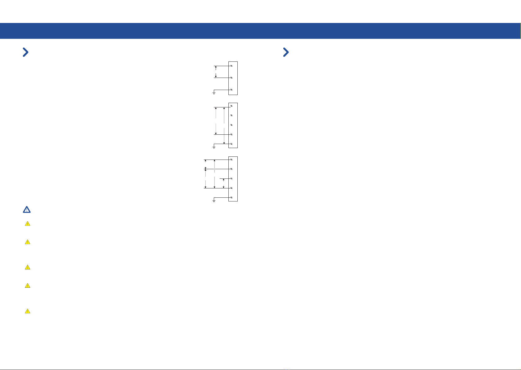
Power supply
Warning
Normally, the earth wire should be properly connected, otherwise the EV charger will not
work.
For situations where there is no earth connection, in order to enable the EV Charger to
operate, it can be set via APP to turn off the earth detection and it will work, but it will reduce
to the leakage protection safety level.
Before installing an AC EV charger, please confirm the type of grid connection available. If
you are unsure of the type of connection available on the service panel, please consult an
electrician or contact ZJBENY for assistance.
Note: Please consult your local electrician or refer to your local code in order to choose the
proper wire for the AC EV charger current.
This BCP series AC EV charger must be grounded via a permanent electrical system or
equipment grounding Conductor.
L
N
PE
230V
L1
L2
L3
230V
N
PE
230V
L1
L2
L3
230V
N
PE
400V
230V
230V
●
For single-phase EV charger, a single-phase wire (L), Neutral and earth
wire must be connected. The phase voltage between the Line and
Neutral wires should be 230V.
230V single-phase power supply
If three phases are applied, all three phases (L1, L2 and L3) and the
neutral line should be connected to each other and the voltage of each
phase to the neutral line should be 230V.
For 3-phase EV charger, connect the single phase wire (L1), the neutral
wire and the earth wire do not connect the other phase wires (L2 or L3).
The phase voltage between the line and neutral wires should be 230V.
400V three-phase power supply with neutral line
●
●
●
●
P-08
Prepare for installation
Installation considerations
Use an appropriate circuit breaker.
To keep the housing weatherproof,use cable glands.
The ev charger doesn't come with the battery for safety shipping, we advise the users to buy
the CR1220 battery or same size battery if need the history record function. Without the batt
ery, the function or the settings need to be reset after charger restart.
Conduit openings are sized for (32 mm) conduit.
Note: Throughout the manual, "conduit" is used as the standard term for the protective tubing that
houses the service wiring. In regions where conduit is not used (Europe for example), a cable
comprised of service wiring enclosed in a protective jacket may be substituted for conduit if
allowed by local regulations.
Conduit needs to be metal and flame retardant.
Three methods are available to install the EV charger.The location of the conduit determines
which installation method to follow. If the conduit runs along the floor or low on the wall, use
the bottom entry configuration. lf the conduit comes from inside the wall, use the rear entry
configuration. lf the available conduit comes from the ceiling, use the top entry installation.
Here are some additional guidelines
●
●
●
●
●
●
●
●
P-10P-09
In the box Installation instructions
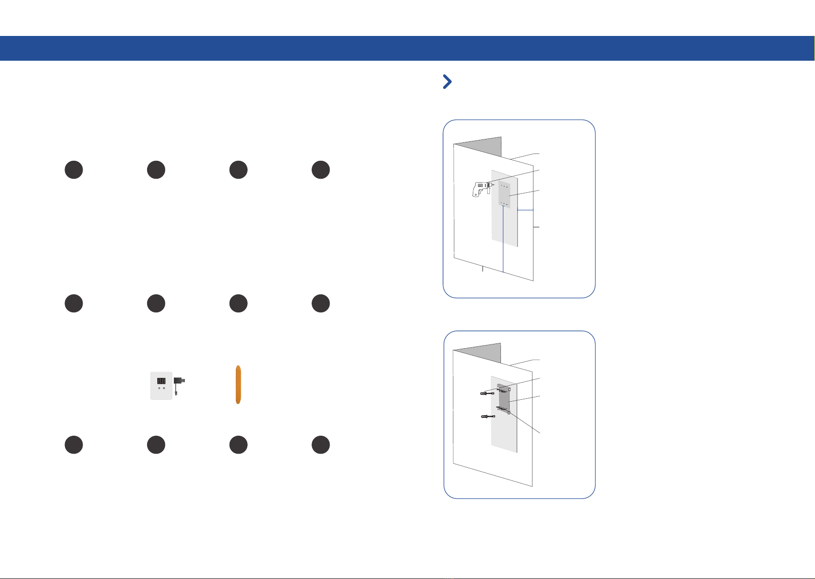
Step-by-step installation instructions
(bottom entry wiring)
wall
≥0.5M
~1.2M
Floor Level
Drill
Side of wall
The 6 pionts
on the position
plate
wall
screwdriver
Mounting
braket
8*40
Expansion bolts
Step 1
Drilling the holes according to the
instruction on the Position template for
different installation and wiring ways.
The bottom of the ⑨positioning plate is 1.2
m away (recommended), if the EV charger is
installed close to the edge of the wall, the
positioning plate should be more than 0.5 m
away from the edge of the wall.
Position
Drilling pilot holes
Step 2
lnstall the Mounting braket
Put the 8*40 Socket head screws' anchoring
into the holes, and use the screw driver make
the 6pcs 8*40 Socket head screws to fix the
Mounting braket on the wall .
① ② ③ ④
⑤ ⑥ ⑦ ⑧
⑨ ⑩ ⑪ ⑫
EV charger
X1
Wire box (optional) Mounting braket RFID card (optional)
X1 X1 X2
M32*1.5 cable gland
X1
M6*8 screws 8*40 socket head
screws and anchorings
8*40 flat head screws
and anchorings
X4 X6 X2
Position template
X1
DLB box (optional) Plastic lifter Water-proof cover
X1 X1 X2

P-12P-11
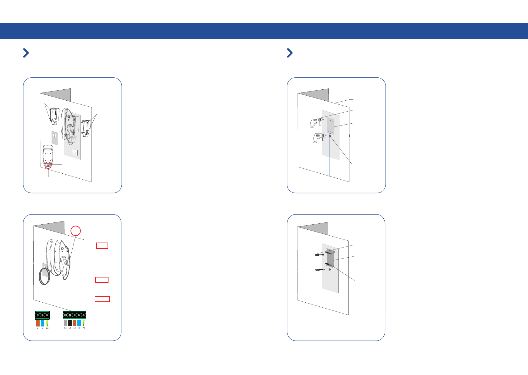
Installation instructions
Step-by-step installation instructions
(bottom entry wiring)
Step 3
Use the 4pcs M6*8 screws to fix the EV
charger to the mounting plate as picture
shows (Screws torque 1.5NM-2.0NM).
Align the side hole of EV charger to the
panel's side holes.
lnstall the EV Charger to the mounting plate
lnstallation
Step 4
Note: Consult with your local electrician or
refer to your local code for proper wire
sizing appropriate for the currents in your
EV Charger.
Wiring
Note: lt is the installer's responsibility to
identify whether additional grounding is
required to ensure that local regulations are
met. Grounding must be installed at the
power source and not at the cable entry to
the EV Charger.
As the picture at left shows, use the
screwdriver loosing the screws on the EV
charger cover. Wire the cable to the
according terminal.
Left hole position Right hole
position
M6*8 bolts
Installation instructions
Step-by-step installation instructions
(top entry wiring)
Step 1
Position
The bottom of the ⑨positioning plate is
1.2 m away (recommended), if the EV
charger is installed close to the edge of
the wall, the positioning plate should be
more than 0.5 m away from the edge of
the wall.
Drilling pilot holes
Drilling the holes according to the
instruction on the Position template for
different installation and wiring ways.
Step 2
Fix the wire box
Put the 8*40 flat head screws' anchoring
into the holes and use the screw driver
make the 2pcs 8*40 flat head screws to fix
the Wire box Mounting Template on the
wall.
wall
≥0.5M
~1.2M
Floor Level
Drill
Side of wall
Two points on
the top and
bottom of
position plate
screwdriver
PS:Hooks and
socketexcluded only for reference
Wire box
8*40
Expansion bolts
Wiring diagram
Single-phase
wiring diagram
Three-phase
wiring diagram
P-13 P-14
Installation instructions
Step-by-step installation instructions
(top entry wiring)
Step 3
Find the hole for cut out on the back of EV
charger.
Cut out on the back of the EV charger.
Use the 4pcs M6*8 screws to fix the EV
charger to the mounting plate as picture
shows (Screws torque 1.5NM-2.0NM).
Step 4
Wiring
Note: lt is the installer's responsibility to
identify whether additional grounding is
required to ensure that local regulations are
met. Grounding must be installed at the
power source and not at the cable entry to
the EV Charger.
Note: Consult with your local electrician or
refer to your local code forproper wire
sizing appropriate for the currents in your
EV Charger.
As the picture at left shows, use the
screwdriver loosing the screws on the EV
charger cover. Wire the cable to the
according terminal.
Left hole position Right hole
position
Back of EV charger
perforating
as image
M6*8 bolts
Installation instructions
Step-by-step installation instructions
(rear entry wiring)
Step 1
Drilling pilot holes
Drilling the holes according to the
instruction on the Position template for
different installation and wiring ways.
The bottom of the ⑨positioning plate is 1.2
m away (recommended), if the EV charger
is installed close to the edge of the wall, the
positioning plate should be more than 0.5 m
away from the edge of the wall.
Position
Step 2
lnstall the Mounting braket.
Put the 8*40 socket head screws' anchoring
into the holes, and use the screw driver
make the 6pcs 8*40 Socket head screws to
fix the mounting braket on the wall .
screwdriver
8*40
Expansion bolts
wall
≥0.5M
~1.2M
Floor Level
Drill
Side of wall
The 6 pionts
on the
position plate
Hole for rearentry
(not limited to the
wall only)
Mounting
braket
Power cable
wiring diagram
lnsert power cord
into the top of
connection box
wiring diagram
Single-phase Three-phase
wiring diagram
Cable box with built
-in cable through EV
charger wiring position

P-15 P-16
Installation instructions
Step-by-step installation instructions
(rear entry wiring)
Step 3
Find the hole for cut out on the back of EV
charger.
lnstall the EV Charger to the mounting
plate.
Use the 4pcs M6*8 screws to fix the EV
charger to the mounting plate as picture
shows (Screws torque 1.5NM-2.0NM).
Step 4
Note: lt is the installer's responsibility to
identify whether additional grounding is
required to ensure that local regulations are
met. Grounding must be installed at the
power sourceand not at the cable entry to
the EV Charger.
As the picture at left shows, use the
screwdriver loosing the screws on the EV
charger cover. Wire the cable to the
according terminal.
Note: Consult with your local electrician or
refer to your local code for proper wire
sizing appropriate for the currents in your
EV Charger.
Wiring
Left hole position Right hole
position
Back of EV charger
perforating
as image
M6*8 bolts
Installation instructions
Be careful of electric shock! Before use, use a voltmeter to confirm that there is no voltage
on the power supply line or terminal to ensure that the power has been cut off.
Do not connect the power cord before reading and fully understanding all the concepts
introduced in this section. If you are not sure whether the type of power supply on the repair
panel is available, please consult an electrician for assistance.
Warning
●
●
Reinstall the sealing cover and
Turn on power
①. Use a screwdriver to lightly secure the sealing cover by installing
only the top screws at (1.5NM-2.0NM )torque.
②. After sealing cover fixing, put the facia on and fix it on the sealing
cover.
④. Recommend to install a circuit breaker 40A/2P 30MA.
③. If you need to open the front cover, change the internal settings,
please use the ④ plastic lifter to unclench along the edge of the
cover.
●
●
●
Set the operating current
After installation, users can set the maximum operating current of the EV charger in the APP,
Please refer to APP manual for details.
●
●
cable through the hole
on the wall and
connect to the back
hole of EV
Wiring teminals
Three-phase
wiring diagram
①
②
③
④

P-17 P-18
Operating status
Power on checking
NO.
2
3
4
5
6
Check content
Check and ensure the circuit breaker for the EV charger is reasonably selected
Confirm that there is no short circuit between the
AC output L/N/PE of the charging
Confirm that the charging gun is not connected to the vehicle
Ensure the circuit breaker is closed
The charger is powered on, and the power-on selfcheck is
completed in about 10 seconds
After the power-on self-check is completed, observe the status of the LED
indicator. Normal standby: Green breathing light ON.
Equipment Failure: Yellow light on /Red light on (Please find below for reference)
LED light instructions
Operating status
Emergency stop reset button: After press the button,
yellow light is always on, EV Charger function is
suspended. Rotate the button counterclockwise to
recover from EV Charger faults.
Electric leakage test button: Press the button to test
the electric leakage(if the red light is flashing, the EV
Charger detection function of electric leakage is
normal), keep pressing the leakage test button for
10s, the EV Charger connection mode is initialized to
Bluetooth mode. (smart types only)
●
●
Button
Normal Status
LED Status Status Description Potential Cause SolutionLED Behavior
All lights ON,
Yellow and Green
lights are blinking
till green lights
breathing magenta.
Charger Power
ON self test
Lights OFF No power supply No power Check the power
source
Standby
The first green light
breathing magenta.
The 1-6 green lights
ON, brightness
decreases from
top to bottom
RFID initiated while
standby
Emergency
stop reset button
Leakage
test button
●
●
1

P-19 P-20
Operating statusOperating status
Charging
Green lights end in
the middle
Green lights extend
from the middle to
the ends
After RFID
swiping
EV is not ready
Green lights up and
down
No RFID card
swiping
EV is not ready
Charging finished
All green lights ON
Normal Status
LED Status Status Description Potential Cause SolutionLED Behavior
Leakage fault
Red light thrice
All lights strobe
( 4 times per second)
Over Voltage
Under Voltage
Grounding
abnormality
Red lights ON
Red light once
Red light twice
Contactor failure
Emergency stop
protection
Yellow lights ON
1.Reset with
emergency stop
button
2.Check the charger
connector or vehicle
for leakage
Leakage happens
Contactor adhesion
or tripping
1.Check the power
supply
2.Check the wire
of power supply
1.Check the power
supply
2.Check the wire
of power supply
Check whether the
grid connection and
charger wiring is
correct
The ground wire is
not wired or the
neutral wire is
reversed
Power supply
has short circuit
or unstable
Power supply
voltage is
insufficient
Check whether
the vehicle charging
module is normal
Rotate the
emergency stop
button Pop-up
reset
Emergency stop
button is pressed
Fault Status
LED Status Status Description Potential Cause SolutionLED Behavior

P-21 P-22
Operating statusOperating status
Abnormal CP
signal
LED board is
offline
DLB is offline
Alternating red and
yellow continuously
Red for 0.5 seconds
followed by yellow
for 0.5 seconds
Yellow light ON
triple
Yellow light ON
once, red light
ON once
Abnormal CC
signal
DLB abnormal
Yellow light ON
once, red light
ON twice
Over temperature
alarm
Red light flashes
(Quartic per
second)
Check the
connection
between DLB box
and charger
The DLB
connection is
loose
The connection
between the DLB
box and the CT is
loose or the CT is
not clamped
High temperature
Open the charger
cover and check
whether the light
board cable is
connected correctly
and firmly
Check whether the
charger connector
is firmly inserted
The connection
between the
charger and the
vehicle is loose
LED board is fault
or loosing
1.Check the CT of
the DLB box is in the
correct position
2.Check whether the
DLB box CT is firmly
clamped
3.Check if the phase
sequence of the DLB
box CT is correct
4.Check if the
connection between
the DLB box CT and
the DLB box is firm
1.Wait for charger
cooling
2.Ensure the wiring
of charger terminal
is not loosing
1.Check if the
connector is with
water leakage in
2.Ensure the
connector is
matched with EV
The connection
between the
charger and the
vehicle is loose
Red light flashes
continuously
(Once per second)
Over current Short circuit may
happen
Call for
professional repair
Red and yellow
lights flash once
Fault Status
LED Status Status Description Potential Cause SolutionLED Behavior
Buzzer prompt description
Buzzer
Short buzzing one sound
Short buzzing two sounds
Long buzzing one sound
Status Operating
Swipe to start
Swipe to quit
Swipe failure
Start charging
Stop charging
NONE
Open Google Play
Click Search bar
Input “Z-BOX”
Z-BOX
Z-BOX
Find ““Z-BOX”APP”
Click “Download”
Open APP Store
Click Search bar
Input “Z-BOX”
Click “Download”
Start to use? Download the APP here
Z-BOX
Z-BOX
Find ““Z-BOX”APP”
Android IOS

P-23
Maintenance instructions
Safety notice
Operation and maintenance risk notification
ln the event of a power failure or power failure, professional personnel or authorized
operation and maintenance personnel must perform maintenance, otherwise there may be a
risk of electric shock; charging equipment maintenance is not allowed when the power is not
disconnected, and there is a risk of electric shock.
Do not disassemble or modify charging facilities and wiring without authorization, otherwise it
may cause fire and electric shock accidents.
There should be no combustible and combustible materials around the charging equipment.
lf there is any, it should be cleaned up in time, othewise there is a risk of fire.
The emergency stop switch should be inspected and maintained regularly to ensure that the
emergency stop switch is effective.
●
●
●
●
Use risk notification
lt is strictly forbidden to use the charger in the case of equipment failure. Do not operate
without authorization when the charging is abnormal. lf you find any abnormalities, please
contact the staff in time.
In the event of fire, flooding of charging facilities, etc., it is strictly forbidden to approach the
charging equipment. Please inform personnel familiar with the equipment and emergency
treatment methods for emergency treatment in time.
Please confirm whether the parameters of the electric vehicle and the charging equipment
match before use, otherwise it may cause damage to the vehicle.
Please strictly follow the operating procedures and prompts on the charging equipment,
otherwise there is a risk of electric shock and fire.
Guardians should take good care of children when they are moving around charging facilities
to avoid accidents such as electric shock.
●
●
●
●
P-24
Maintenance instructions
Product overhaul
ln order to ensure the normal service life of the charging pile and reduce the risk during use, it
must be overhauled with in the specified time period; the overhaul of the equipment should be
carried out by professionals, band qualified and safe overhaul tools should be used.
Regularly check whether the product is damaged.
Ensure that the emergency stop, circuit breaker and other components of the product can be
used under any circumstances, and conduct regular tests.
lf a ground fault occurs, first make sure that the grounding cable carries voltage, and then
check that there is no high voltage in the system, and then repair the charger.
●
●
●
Warranty description
Non-professionals are not allowed to repair the chargers. Any problems during installation or use,
please contact the dealer first.
Free warranty is available for any damages or failures due to the chargers’ quality problems
since 3 years from the date of producing at the factory.
Any damages caused by failure operatings, irresistible natural reasons, wrong install or use
against with the instructions, is not covered by the warranty.
●
●
●
●

P-25 P-26
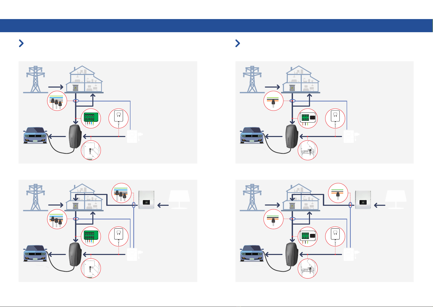
1 Phase Grid 2 Phase Grid
DLB Installation instructions
DLB Installation instructions
Normal DLB Normal DLB
Solar DLB Solar DLB
L1
L2
L3
N
PE
L1
L2
L3
N
PE
L1
L2
L3
N
PE
L1
L2
L3
N
PE
L1
L2
L3
N
PE
L1
L2
L3
N
PE
CT
Clamp
State Grid Inverter Solar Panel
DLB
Electric Car
EV Charger
CT
Clamp
CT
Clamp
State Grid
DLB
Electric Car
EV Charger
Other
household
Load
Appliances
CT
Clamp
State Grid Inverter Solar Panel
DLB
Electric Car
EV Charger
CT
Clamp
Distribution
Box
CT
Clamp
State Grid
DLB
Electric Car
EV Charger
Distribution
Box
Other
household
Load
Appliances
Other
household
Load
Appliances
Distribution
Box
Distribution
Box
Other
household
Load
Appliances
P-27 P-28
2 Live wire 1 earth wire power supply method
DLB Installation instructions
DLB Installation instructions
3 Phase Grid
L1
L2
PE
L1 L2 PE
L1 L2 PE
L1
L2
PE
L1
L2
L3
N
PE
L1
L2
L3
N
PE
L1
L2
L3
N
PE
L1
L2
PE
L1 L2 PE
L1 L2 PE
Normal DLB Normal DLB
Solar DLB Solar DLB
Note: It is suitable for the power
grid where the voltage between L1
and L2 is about 220V. Meanwhile,
the grounding detection of EV
charger needs to be turned off.
CT
Clamp
State Grid Inverter Solar Panel
DLB
Electric Car
EV Charger
CT
Clamp
CT
Clamp
State Grid
DLB
Electric Car
EV Charger
Other
household
Load
Appliances
CT
Clamp
State Grid Inverter Solar Panel
DLB
Electric Car
EV Charger
CT
Clamp
Distribution
Box
CT
Clamp
State Grid
DLB
Electric Car
EV Charger
Distribution
Box
Other
household
Load
Appliances
Other
household
Load
Appliances
Distribution
Box
Distribution
Box
Other
household
Load
Appliances
Table of contents


