4
b As soon as you open the packaging,
check immediately that the contents are
all present and undamaged. Contact the
reseller from whom you purchased the
product if you notice any problems.
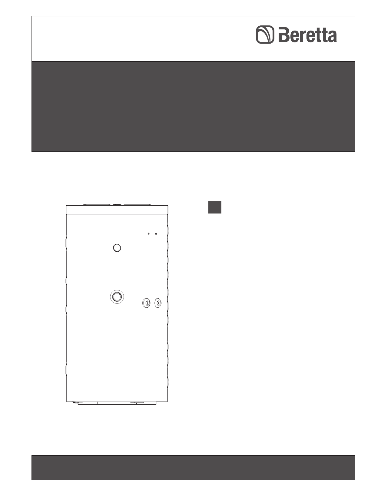
b This BERETTA HYBRID STOR combi-
nation storage cylinder must be installed
by a qualified installer. On completion of
the installation, the installer must issue
the owner with a declaration of confor-
mity confirming that the installation has
been completed to the highest stan-
dards in compliance with the instructions
provided in this instruction manual, and
that it conforms to all applicable laws
and standards.
b This BERETTA HYBRID STOR combi-
nation storage heater must only be used
for the purpose specified and for which it
is designed. The manufacturer declines
all responsibility, contractual or other, for
damage to property or injury to persons
or animals caused by improper installa-
tion, adjustment, maintenance or use.
b If you notice any water leaking from the
cylinder, disconnect it immediately from
the mains electricity supply, shut off the
water supply, and notify your Technical
Assistance Centre or a qualified techni-
cian immediately.
b This combination storage cylinder must
be serviced at least once a year.
If the combination storage cylinder is not
going to be used for an extended period
of time, prepare it for shut-down as fol-
lows:
- Turn the system’s main power switch
OFF
- Drain the solar water circuit
- Close the fuel cock and heating water
cock
- Drain the central heating circuit and
domestic hot water circuit if there is
any risk of freezing
b Anti-freeze (propylene glycol) is availa-
ble separately and must be mixed with
water in a percentage varying from 30%
to 50%.
b This instruction manual is an integral
part of the appliance. It must be kept
safe and must ALWAYS accompany the
appliance, even if it is sold to another
owner or transferred to another user or
to another installation. If you damage or
lose this manual, order a replacement
immediately from your local Technical
Assistance Centre.
The operation of any appliance that uses
electrical power and water demands that a
number of fundamental safety precautions be
respected. In particular:
aDo not allow children or infirm persons to
operate the combination storage cylin-
der unsupervised.
aDo not touch the combination storage
cylinder when barefoot or wet.
aNever clean or service the combination
storage cylinder without first disconnec-
ting it from the mains electricity supply
by turning the main power switch and
the control panel switch OFF.
aDo not interfere with any control devi-
ces without specific authorisation and
instructions from the manufacturer.
aDo not leave packaging material within
the reach of children, since it can beco-
me a potential hazard.
aIf the pressure in the solar heating circuit
drops, do not top up with water alone,
since this increases the risk of damage
from freezing.
aDo not use connections or safety devi-
ces or fittings (expansion vessels, pipes,
insulation) that are not specifically desi-
gned and tested for use in solar heating
installations.
1 SAFETY PRECAUTIONS