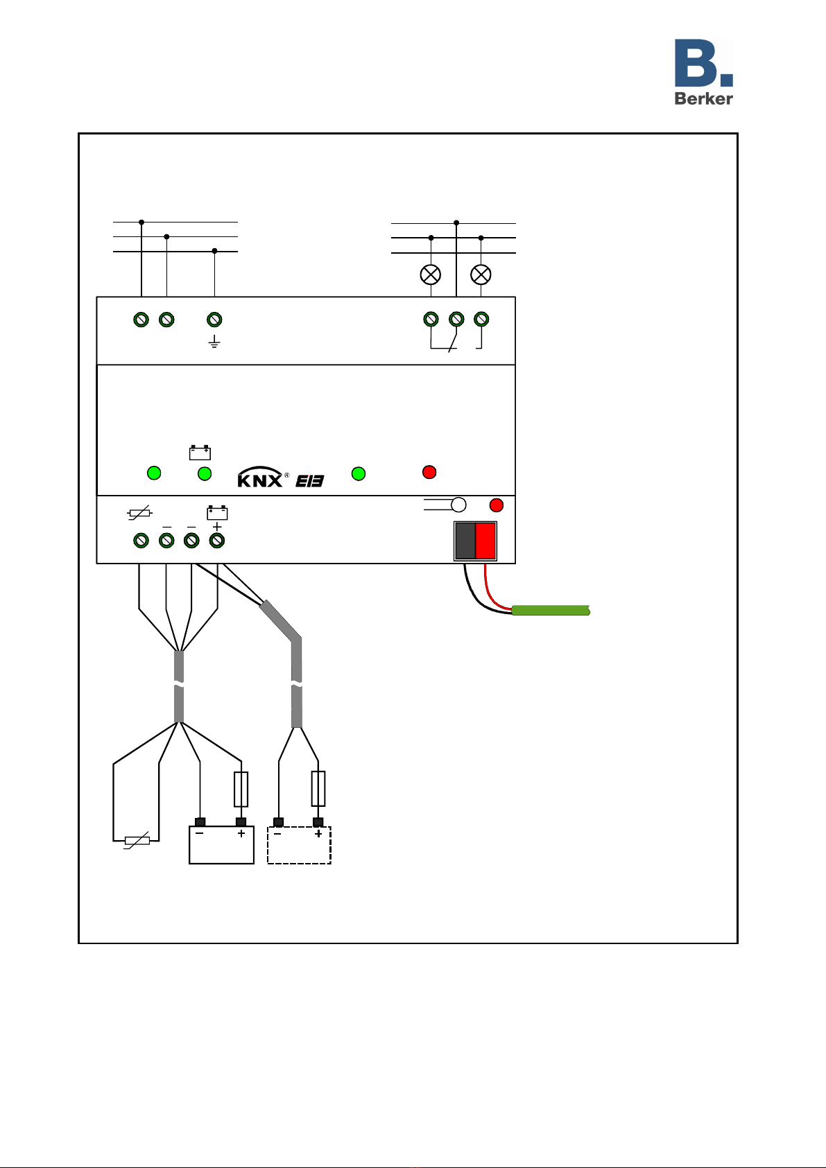
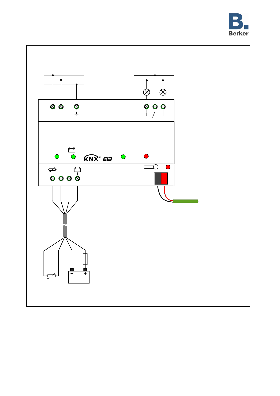
Power supply 640mA RMD
uninterruptible
75010015
Technical
Documentation
© Gebr.Berker 2007 Version: 06.07.2007 Page: 8 / 9
(Subject to prior change) 75010015.doc Part 8
Hardware remarks (continued)
•Fault message:
- The uninterruptible power supply permanently monitors the connected bus line, the mains voltage and
the storage battery voltage. In the event of faults, the green LED "Operation" goes out. The cause of
the fault is indicated by means of the various LEDs on the front panel of the device and by the fault
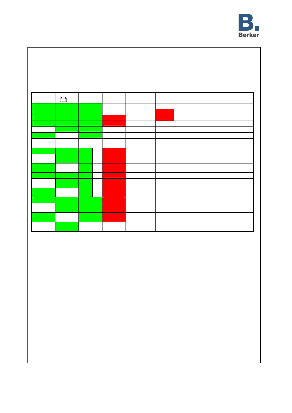
signalling contact in accordance with the following table:
LED
"230 V OK"
LED
" OK" LED
"Operation"
LED
"Overload"
Fault signalling
contact Reset
LED State / fault cause
green green green off normal off normal operation
green green green off normal red reset is active
green green green flashes red
fault red overvoltage, automatic reset is active.
green green green flashes red
fault off overvoltage fault stored, fault rectified
off green green off fault off mains failure, battery operation
green off green off fault off no battery, battery fault or battery empty
off off off off fault off mains failure and no battery, battery fault or
battery empty
green green green
off*
red fault off overload or short circuit
off green green
off*
red fault off overload without short circuit and mains
failure, battery operation
green off green
off*
red fault off overload without short circuit, no battery,
battery fault or battery empty
green green green
off*
flashes red
fault off overvoltage
off green green
off*
flashes red
fault off overvoltage and mains failure, battery
operation
green off green
off*
flashes red
fault off overvoltage and no battery, battery fault or
battery empty
green green green red fault off overload, output voltage OK
off green green red fault off overload, output voltage OK, mains failure,
battery operation
green off green red fault off overload, output voltage OK, mains
operation, no battery
--- flashes
green --- --- fault off battery defective or battery connected with
reverse polarity
*: green or off / ---: condition irrelevant.
In the event of overload or overvoltage at the bus output, the fault message is stored. In this case, the
potential-free change-over contact and the corresponding LED continue to remain in the fault state
even if the cause of the fault message no longer exists and if the bus is again supplied with power.
Although the system seems to work properly, the fault cause must be located and rectified by a
service technician as the fault may be a recurrent fault. When the fault has been rectified, the stored
alarm can be acknowledged and deleted by a single press on the reset button. The potential-free
contact switches back to normal position and the LED indicates the normal state of operation.
Pressing the reset button a second time will reset the bus. If the fault has not been removed
beforehand, a press on the reset button will result in a bus reset all right, but the fault remains stored
and the potential-free change-over contact and the LED continue to remain in the fault state.
- In the event of a mains failure, the bus line will be supplied from the connected storage battery, i.e the
failure has no effect on the bus voltage. When the mains supply fails, the potential-free change-over
contact switches to fault position and the LED "230 V OK" goes out. On return of the mains voltage,
the potential-free change-over contact goes back to normal position and the LED is lit up green. The
fault message is not stored.
- If the fault messages are to be indicated, it is possible to connect LEDs or signal lamps to the fault
signalling contact. A message can also be transmitted automatically to a service technician, if a
suitable phone dialler is connected to the fault signalling contact.