Berker 4582 Product guide

Page 1/7 03-2015
WLAN Access-Point ush-mounted
4582
WLAN Access-Point ush-mounted, PoE
4583
Operating and assembly instructions
Safety instructions
Electrical equipment may only be installed and assembled by a qualied electrician in
accordance with the relevant installation standards, guidelines, regulations, directives,
safety and accident prevention regulations of the country.
Hazard due to electric shock. Disconnect before working on the device. Take into
account all circuit breakers that supply dangerous voltages to the device.
Failure to comply with these instructions may result in damage to the device, re, or oth-
er hazards.
These instructions are an integral component of the product and must be retained by the
end user.
Design and layout of the device
(8)
(7)
(9)
(1)
(4)
(3)
(6)
(5)
Figure 1: Front view WLAN Access-Point
WLAN Access-Point ush-mounted
6LE001255A

Page 2/7 03-2015
(7)
(9)
(2)
(4)
(3)
(6)
(5)
Figure 2: Front view WLAN Access-Point, PoE
(1) 5pole terminal block
(2) 9pole terminal block
(3) Contact pins
(4) Position reed contact for reset
(5) blue LED (WLAN)
(6) orange LED (LAN)
(7) RJ45 jack
(8) Mains voltage connection
(9) green control LED for the network cable connected to terminal block (1, 2)
Function
The WLAN Access-Point extends the possible uses of modern network technologies for mobile
end devices with low power consumption and radio emission. Additional settings can limit the
device from other Access-Points in order to prevent overcoupling of the WLAN areas and losses
of the data rates.
This device can be used in three operating modes – namely as:
–Access-Point for wirelessly communicating devices
–Repeater for increasing the range in the WLAN network
–Client for connecting to devices that do not have their own WLAN adapter.
Detailed information on conguration and settings are available for downloading at
www.berker.com.
Correct use
–only suitable for operation in indoor areas
–Installation into wall box according to DIN 49073
WLAN Access-Point ush-mounted
6LE001255A

Page 3/7 03-2015
Operation
LED displays
Two coloured LEDs illuminate the RJ45 jack and indicate what status the network functions of
the Access-Points are in.
Display Status
blue LED (5) lights up permanently WLAN is active.
blue LED (5) ashes Reset starts.
The device is restarted.
orange LED (6) lights up permanently LAN is active, a connection is available.
orange LED (6) ashes LAN is active, data transfer takes place.
Or:
Device is reset to factory settings.
Table 1: Displays on the status LEDs
Restart device
If the device does not function properly, it might be necessary to restart the device.
Keep a permanent magnet over the position of the reed contact (4) on the cover of the
Access-Point for 2 ...4 seconds.
The reed contact on the Access-Point is triggered. The blue LED (5) ashes. Reset starts.
Reset device to factory settings
Keep a permanent magnet over the position of the reed contact (4) on the cover of the
Access-Point for 5 ..10 seconds.
The reed contact on the Access-Point is triggered. The orange LED (6) ashes The device
restarts and loads the factory settings.
If access to the Access-Point is no longer possible, please proceed according to the congu-
ration instructions at www.berker.com.
Information for electricians
Installation and electrical connection
DANGER!
Touching live parts can result in an electric shock.
An electric shock can be lethal.
Disconnect the connecting cables before working on the device and cover all
live parts in the area!
ç
It is imperative to install the device at a height of 0.3 … 1.1 m to ensure functional reliability.
WLAN Access-Point ush-mounted
6LE001255A
Page 4/7 03-2015
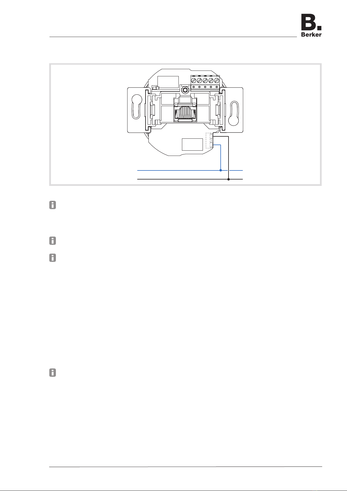
WLAN Access-Point (order no. 4582)
Connect device to power supply
N
L
(8)
Figure 3: Connection supply voltage
Live cables and network cables must always be laid separately from each other to the wall
box.
Run the mains cable into the wall box from below.
Strip cable adequately and connect cables to the plug-in terminals (8) (Figure 3).
To release the plug-in terminal, press down the retaining lug e.g. using a small at-bladed
screwdriver and pull out the cables.
The power supply of active components, such as from this device or from a PC, must be
disconnected from the other consumers in order to prevent any disruptions in the network.
For this purpose, use a separate circuit secured by an automatic cutout or circuit breaker as
well as appropriate overvoltage protection if necessary. The circuit and connected socket
outlets must be labelled clearly e.g. with EDV.
Connect network cable
Run the mains cable into the wall box from above.
Shorten the cable to a length of approx. 90 mm from the bottom of the wall box.
Strip the cable to approx. 80 mm. When doing so, keep the pair shielding and twist of the
pair and wires as far as possible.
Twist the outer shielding S and afx it in a conductor sleeve (1 mm²) if necessary.
Pull off 5pole terminal block (1) from the device and lay the wires according to the prescribed
colour coding (Table 2). Cut off wires not required.
The assignments on the terminal block must match those of the patch panel in the network.
Mount terminal block (1) onto the contact pins (3) (Figure 4).
Mount the device into the wall box.
Unscrew cover.
Switch ON power supply.
Device with the factory settings is ready for operation. A conguration for individual settings
can be made.
WLAN Access-Point ush-mounted
6LE001255A

Page 5/7 03-2015
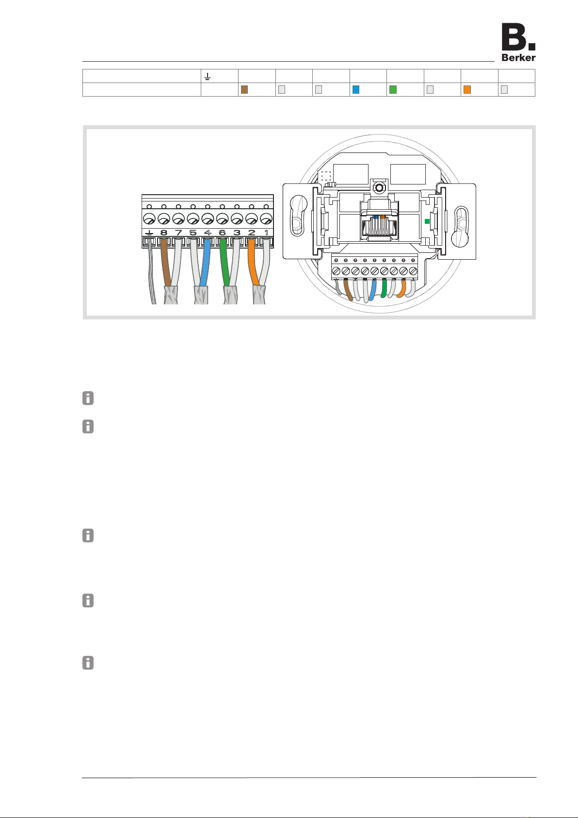
Designation terminal 6321
Assignment S
Table 2: Assignment on the terminal block (1) of the WLAN Access-Point
Figure 4
WLAN Access-Point, PoE (order no. 4583)
Connect network cable
Run the mains cable preferably into the wall box from below.
Shorten the cable to a length of approx. 90 mm from the bottom of the wall box.
Strip the cable to approx. 80 mm. When doing so, keep the pair shielding and twist of the
pair and wires as far as possible.
Twist the outer shielding S and afx it in a conductor sleeve (1 mm²) if necessary.
Pull off 9pole terminal block (2) from the device and lay the wires according to the prescribed
colour coding (Table 3).
The assignments on the terminal block (2) must match those of the patch panel in the net-
work.
Mount terminal block onto the contact pins (3) (Figure 5).
Mount the device into the wall box.
Unscrew cover.
Device with the factory settings is ready for operation. A conguration for individual settings
can be made.
WLAN Access-Point ush-mounted
6LE001255A
Page 6/7 03-2015
Designation terminal 87546321
Assignment S
Table 3: Assignment on the terminal block (2) of the WLAN Access-Point, PoE
Figure 5
Information regarding conguration
It is advisable to carry out the Initial conguration with patch cable via the LAN interface of the
device.
The WLAN IP-address of the conguring device must be within the range 192.168.0.xxx
(x ≥ 0 ≤ 2 55, x ≠ 5), subnet: 255.255.255.0.
After the initial conguration, the password should denitely be changed. When changing the
password or SSD, do not use any spaces, numbers or characters such as ä, ü, ö, or ß.
Congure device via patch cable
Connect the RJ45 jack (7) at the Access-Point via a patch cable to the LAN interface e.g. via
a PC.
In the Internet browser enter the IP address http://192.168.0.5.
Log on with the password admin.
The password admin applies to the default state.
Congure device via WLAN
In the WLAN settings of the devices intended for the conguration, such as a tablet PC,
select the the WLAN Access-Point.
The Access-Point logs on in the network with the WLAN name (SSID) Berker.
Log on at the Access-Point with the WLAN password wireless123.
In the Internet browser enter the IP address http://192.168.0.5.
Log on with the password admin.
The password admin applies to the default state.
WLAN Access-Point ush-mounted
6LE001255A

Page 7/7 03-2015
Appendix
Technical Data
RJ45 connection socket 10/100 MBit/s
Radio range 2.4 GHz
Radio data rate 150 MBit/s
Radio standard IEEE 802.11 b/g/n
Encryptions WEP, WPA, WPA2
Operating temperature -5 ... +45 °C
Degree of protection accord. to DIN 60529 IP20
WLAN Access-Point ash-mounted, order no. 4582
Rated voltage 100 ... 240 V~
Mains frequency 50 ... 60 Hz
Power consumption 1.8 W
Conductor cross-section (mains cable) max. 2.5 mm2
WLAN Access-Point ash-mounted, PoE, order no. 4583
Power supply accord. to IEEE803.2at (class 0) 48 V, PoE
Power consumption ≤ 3 W
PoE supply to RJ45 jack accord. to IEEE803.2at (class 2) 48 V/6.49 W
Warranty
We reserve the right to make technical and formal changes to the product in the interest of tech-
nical progress.
Our products are under guarantee within the scope of the statutory provisions.
If you have a warranty claim, please contact the point of sale or ship the device postage free
with a description of the fault to the appropriate regional representative.
Address of manufacturer
Berker GmbH & Co. KG
Klagebach 38
58579 Schalksmühle/Germany
Phone: + 49 (0) 23 55/90 5-0
Fax: + 49 (0) 23 55/90 5-3111
berker.com
WLAN Access-Point ush-mounted
6LE001255A
This manual suits for next models
1
Table of contents
Other Berker Wireless Access Point manuals

Popular Wireless Access Point manuals by other brands


D-Link
D-Link DAP-1533 user manual

LG-Ericsson
LG-Ericsson EARU 1211 user manual

ZyXEL Communications
ZyXEL Communications NWA-3160 user guide

LiveWatch
LiveWatch 43562385 quick start guide

TP-Link
TP-Link Omada TPL-EAP225 Quick installation guide

D-Link
D-Link DAP-2590 - AirPremier N Dual Band PoE Access... Quick installation guide

Huawei
Huawei AP8130DN Product description

NETGEAR
NETGEAR Orbi Pro Satellite quick start guide

Leggett & Platt
Leggett & Platt LP CONNECT user guide

EnGenius
EnGenius ECB150 Quick installation guide

Lucent Technologies
Lucent Technologies WaveACCESS NET MDR232 installation guide

Draytek
Draytek VigorAP 700 user guide