BERMAD Omega User manual

Quick Start Guide
Scan QR code to view full manual

2 3
TABLE OF CONTENTS
Safety ....................................... 4
Introduction
Omega Controller ........................... 5
Typical Connection Layout .................. 6
Cloud Management System ................ 8
Mounting OMEGA
Wall Mounting............................... 10
Valve Mounting ............................. 12
Pole Mounting .............................. 16
Powering OMEGA
Battery Power Supply....................... 20
External Power Source...................... 22
Connecting Peripherals
Latch Output Connections .................. 24
Digital Input Connections ................... 26
Analog Input Connections .................. 28
Communicating via RS-485 Cable......... 30
4 5
SAFETY
Before operating Omega, please read the safety
section found in the Omega Installation and
Operation Guide
NOTE: This product conforms
with FCC and CE regulations.
Please see the installation
and operation guide for more
information
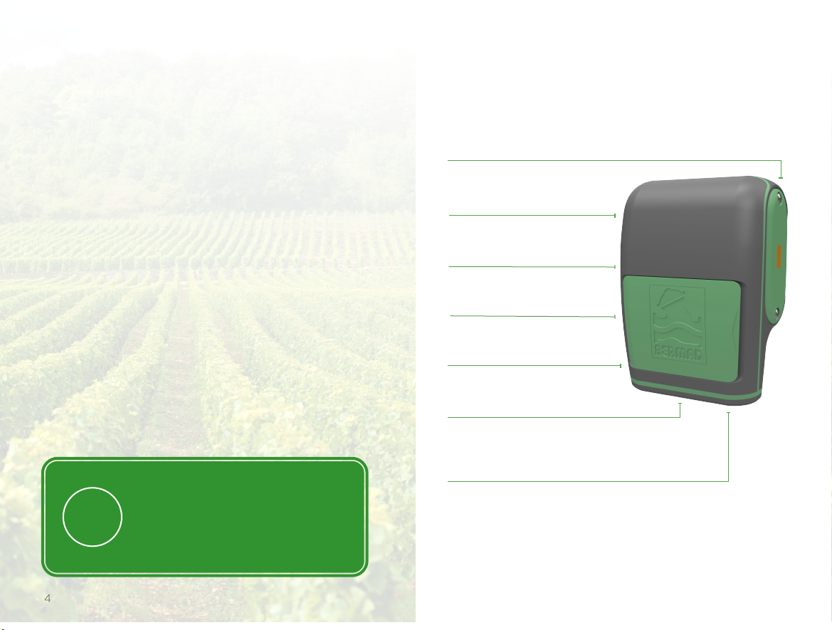
INTRODUCTION
Omega Controller
RS-485 connector¹
SIM card
Connection terminals
Mounting bracket
Battery compartment
Power connector
SMA connector for
external antenna²
1Available in Omega RS, RF, and X models only
2Not standard
6 7
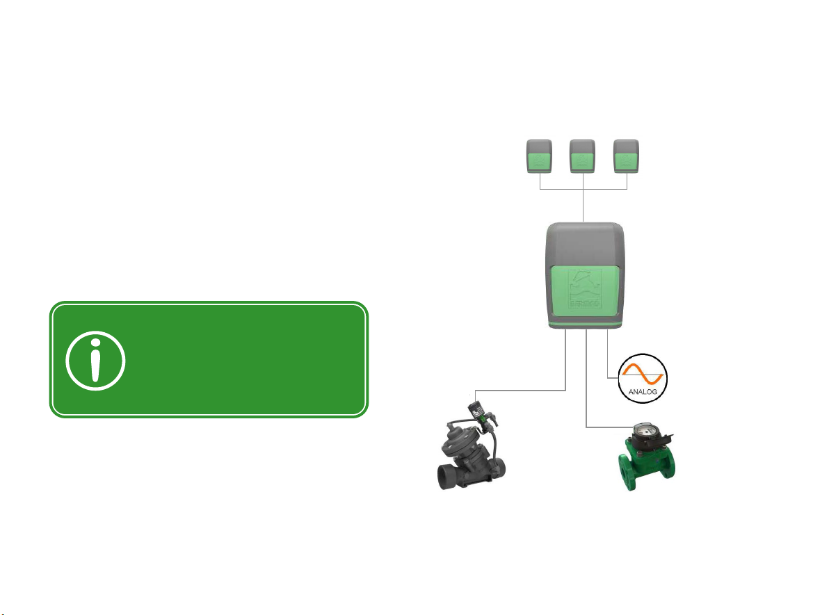
Typical Connection Layout
The following can connect to the Omega
controller’s connection terminals:
Latch output connection terminals:
▪Latch solenoids - irrigation valves and
master valve
▪Latch relay - water pumps
Digital input connection terminals:
▪Water meters
▪Dry contact and open collector digital
sensors
Analog input connection terminals:
▪Analog sensors
Tip: When installing open
collector sensors, verify
the polarity matches what
is marked on the Omega
connector board
Up to ten extension controllers – total of 44
latch outputs, 44 digital inputs, and 22 analog
inputs (RS models only)
Up to two
analog inputs
Up to four
digital inputs
Up to five
latch outputs
RS-485

8 9
Cloud Management System
BERMAD Cloud provides a centralized web-based
user interface for the Omega controller, allowing
for anywhere-anytime management and real-
time visual monitoring of the irrigation system
using a PC, tablet, or smartphone.
BERMAD Cloud offers the following benefits:
Password protected login
Dynamic dashboard
Irrigation management and monitoring tools
Alert controls
Log information and report generation
Omega
Cloud
Management
software
NB-IoT
GPRS
BLE

10 11
MOUNTING OMEGA
Wall Mounting
1. Attach the mounting
bracket to the wall using
two screws
2. Position the Omega
controller onto the
bracket
3. Verify the bracket
is fully inserted into the
controller slot
12 13
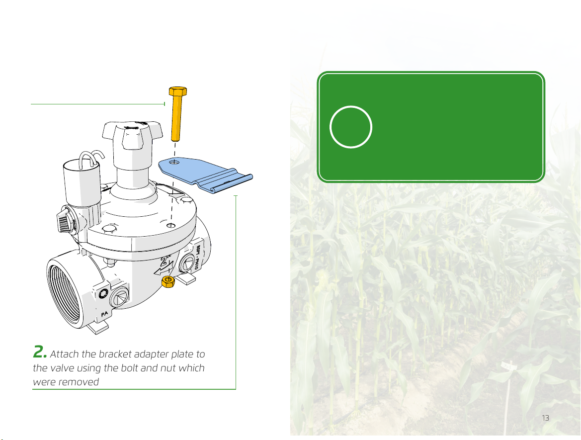
Valve Mounting
1. Remove the bolt and
nut from the valve
2. Attach the bracket adapter plate to
the valve using the bolt and nut which
were removed
NOTE: The bracket adapter
plate provided by BERMAD
is designed for horizontal
installations, and is suitable
for the BERMAD 200 series
valves without further need for
adjustments

14 15
3. Insert the mounting
bracket into the Omega
controller
4. Verify the bracket
is fully inserted into
the controller slot
6. Verify the bracket
adapter plate clicks in place
and is securely fastened to
the mounting bracket
5. Position the mounting
bracket onto the bracket
adapter plate

16 17
Pole Mounting
1. Attach the bracket adapter plate to the
U-clamp using a bolt and nut
NOTE: The U-clamp is an
optional accessory that must
be ordered separately. The
U-clamp provided by BERMAD
fits 1” (DN25) to 2” (DN50) pole
diameters
2. Attach the U-clamp
to the pole using two nuts

18 19
5. Position the mounting
bracket onto the bracket adapter
plate
6. Verify the bracket adapter
plate clicks in place and is
securely fastened to the
mounting bracket
3. Insert the mounting
bracket into the Omega
controller
4. Verify the bracket
is fully inserted into
the controller slot
20 21
POWERING OMEGA
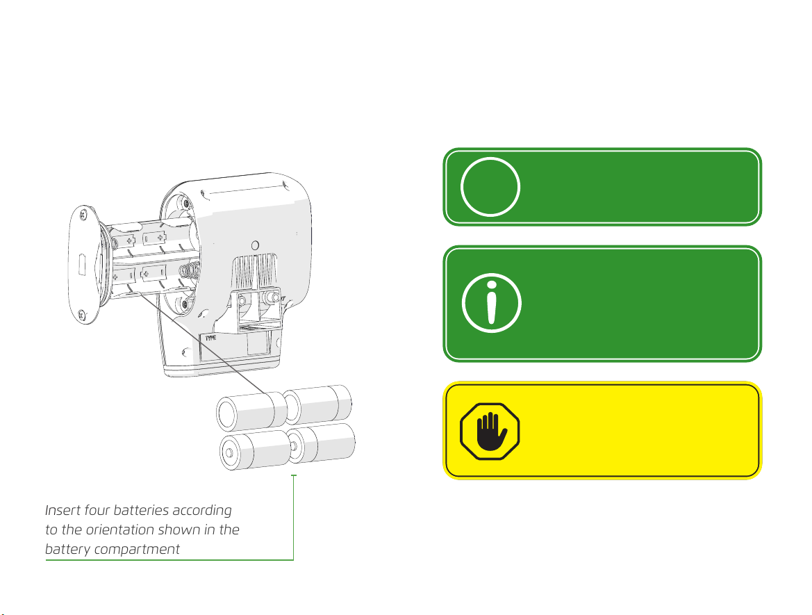
Battery Power Supply
The Omega controller is powered by four LR-14
(C-size) alkaline batteries (see battery datasheet in
full manual)
Insert four batteries according
to the orientation shown in the
battery compartment
CAUTION: Running the Omega
controller on battery power in
online mode shortens battery
life significantly
NOTE: In offline mode, the
controller can run on battery
power for up to five years
Tip: For best performance
in outdoor installation, use
batteries with an operating
temperature range of
-18° to 55° C or greater

22 23
External Power Source
The Omega controller can be powered by electrical
grid power, external high-capacity batteries, or
solar panels
CAUTION:
• Connect the power cable to
the Omega power connectors
before turning on the power
source
• The Omega controller must
first be unplugged from the
external power source before
disconnecting the power
supply cables from the power
connectors
NOTE: An external power
supply is necessary if operating
the Omega controller in online
mode for an extended amount
of time
Verify the power supply
provides 9-24 VDC/1 A
Verify the external power source
polarity matches the polarity marked on
the connector board

24 25
CONNECTING PERIPHERALS
Latch Output Connections
Up to five devices (such as valves and water
pumps) can be connected to the Omega controller
latch outputs
NOTE: The Omega RS model
features up to four latch
outputs and one RS-485
MODBUS
Pump
Latch
relay
1 2 3
54
Activated via 25
ms pulses
Latch solenoid valve
A relay must be
connected between the
latch output and the
pump

26 27
Digital Input Connections
Up to four devices (such as water meters and
digital sensors) can be connected to the Omega
controller digital inputs.
NOTE: Digital inputs can be
connected to devices with
one of the following outputs:
- Dry contact
- Open collector
CAUTION: Ensure the open
collector connects according to
the input polarity marked on
the connector board.
1 2 3 4

28 29
Analog Input Connections
Up to two devices (such as the following types of
analog sensors) can be connected to the Omega
controller analog inputs.
NOTE: The controller supports
both analog voltage (0-10 V)
and analog current (4-20 mA)
sensor
CAUTION: Ensure setting the
correct analog protocol before
connecting the sensor
Two-wire active analog
sensor (connected to an
external power source)
Two-wire passive
analog sensor
Three-wire passive analog
sensor (powered
by the Omega controller)
2
1

30 31
COMMUNICATING VIA
RS-485 CABLE
Additional inputs and outputs can be connected
either wired or wirelessly to the Omega controller
using an RS-485 cable.
Each extension controller can connect to four
latch outputs, four digital inputs, and two
analog inputs
B A G
RS-485
RS models only
Up to ten extension controllers can be
connected in parallel via an RS-485
communication cable

The information contained herein may be changed by BERMAD
without notice. BERMAD shall not be held liable for any errors
©Copyright 2011-2021 BERMAD CS Ltd.
www.bermad.com
PIEA20-OMEGA | May 2021
Other manuals for Omega
2
Table of contents
Popular Farm Equipment manuals by other brands


Harvestec
Harvestec 630 Operator's manual

Tatu Marchesan
Tatu Marchesan GCRO 7010 Operator's manual

Turf Tick Products
Turf Tick Products Turf Tick Original instructions

Raven
Raven SmarTrax installation manual

Rain-Flo Irrigation
Rain-Flo Irrigation 2670 operating manual

FREE RANGE
FREE RANGE HEN HOUSE Assembly instructions