Sipma OS 7520 MIRA User manual

SIPMA S.A.
ul. Budowlana 26
20-469 Lublin, Polska
tel. (+48) 81 74 45 071
www.sipma.pl
OPERATOR’S MANUAL
Bale wrapping machine with damper
system SIPMA OS 7520 MIRA
PKWiU 28.30.34.0
ORIGINAL MANUAL
READ CAREFULLY THE MANUAL
BEFORE USING THE MACHINE

3
NOTE:
The Manufacturer delivers the complete baler together with an operator’s manual and a warranty card. At the
receipt of the baler, the customer should check the machine and the received documents for their completeness.
The machine is subject to the start-up procedure described in the warranty. Conducting the first start-up is a basic
condition of the safe and reliable operation of the machine.
This manual includes information concerning usage, lubrication and operation as well as safety regulations. It
describes all available versions and options, including those that are not provided with the standard version of
the machine.
Dear user!
The machine is constantly being developed; therefore SIPMA S.A. reserves the right to implement
any changes or corrections, as appropriate. Under no circumstances may the recipient demand any
modifications to be made to machines that were delivered earlier on the basis of the above.
The efficiency of the machine depends on many factors, connected with the operating conditions.
It is very important to read the manual carefully before operating the machine, and to have it ready
at hand while working. This will enable you to avoid any accidents, follow the terms of the warranty
and keep the machine in a good technical condition.
For further information regarding the operation of this and other machines manufactured by the
SIPMA Capital Group and for assistance connected with maintenance service and the spare parts
catalogue, contact our sales representatives.
Supplier:
(the box shall be filled in by the supplier upon selling the baler, and it should include the company's name as well as the family name, address and
telephone number of the contact person and the delivery date)
Also the manufacturer of the machine is at your disposal:
SIPMA S.A.: tel.:(48)(81) 744-50-71 or 744-12-81, fax: (48)(81) 744-43-56
Sales Office: tel.:(48)(81) 744-07-81 or 441-44-35, fax: (48)(81) 744-09-64 Technical
service: tel.:(48)(81) 744-03-23 or 441-46-18, fax: (48)(81) 744-09-64
Please ensure that after the first operating season the validation form enclosed in this
operator’s manual is filled in and sent to the manufacturer's address.
For any warranty and service details see the warranty card.

4
ENJOY THE USE OF OUR PRODUCTS THE
OPERATOR’S MANUAL IS AN INTEGRAL PART OF THE
MACHINE EQUIPMENT, KEEP FOR FUTURE
REFERENCE
List of contents
..............................................................................5
1. INTRODUCTION........................................................................................................................6
2. OPERATION SAFETY AND WARNINGS ...............................................................................7
2.1. Fire regulations....................................................................................................................................................10
2.2. Description of residual risk .................................................................................................................................10
2.3. Evaluation of the residual risk during the machine operation .............................................................................11
2.4. Safety signs ........................................................................................................................................................11
3. MACHINE IDENTIFICATION.................................................................................................15
4. MACHINE DESIGNATION AND GENERAL INFORMATION ...........................................16
5. TECHNICAL AND OPERATIONAL SPECIFICATIONS ......................................................17
6. GENERAL SPECIFICATION AND DESCRIPTION...............................................................18
6.1. Sensors...............................................................................................................................................................20
7. CONTROL PANEL....................................................................................................................21
8. DELIVERY, TRANSPORTATION, PREPARING ..................................................................22
8.1. Delivery...............................................................................................................................................................22
8.2. Transportation .....................................................................................................................................................22
8.3. Preparing the machine........................................................................................................................................23
9. MACHINE OPERATION..........................................................................................................27
9.1. Start-up test .........................................................................................................................................................27
9.2. Film for bale wrapping........................................................................................................................................27
9.3. Bale loading and wrapping..................................................................................................................................30
9.4. Bale unloading and film cutting ..........................................................................................................................31
9.5. Design and operation of the bale damper ............................................................................................................32
9.6. Preparing bales for wrapping...............................................................................................................................34
9.7. Reasons of machine malfunction and troubleshooting.......................................................................................34
10. EQUIPMENT AND SPARE PARTS.......................................................................................35
11. MAINTENANCE.....................................................................................................................36
12. LUBRICATION INSTRUCTION............................................................................................36
13. STORAGE................................................................................................................................37
14. DISASSEMBLING AND WORN-OUT PARTS.....................................................................37
15. WARRANTY...........................................................................................................................38
PRODUCT VALIDATION............................................................................................................38
WARRANTY CHART...................................................................................................................40
GENERAL WARRANTY PROCEEDINGS:................................................................................41
START-UP COUPON....................................................................................................................42
COMPLAINT COUPON................................................................................................................44
RECORD OF GUARANTEE REPAIRS.......................................................................................48

5
List of figures
Fig. 1. Obligation to read the content of the Operator’s Manual................................................11
Fig. 2. Attention: Danger of hand injury.......................................................................................11
Fig. 3. Attention: moving bale........................................................................................................11
Fig. 4. Keep a safe distance from the machine..............................................................................11
Fig. 5. All repairs and adjustments on disconnected machine.....................................................12
Fig. 6. Stand clear from the area of the joint hitches ...................................................................12
Fig. 7. Do not operate on slopes of more than 12°........................................................................12
Fig. 8. Danger of burns by a hot oil..............................................................................................12
Fig. 9. Do notoperate themachine until you have read the Operator's Manual..........................12
Fig. 10. Information pictogram......................................................................................................12
Fig. 11. Tire pressure .....................................................................................................................12
Fig. 12. Film routing in the film dispenser...................................................................................12
Fig. 13. Lifting lug..........................................................................................................................12
Fig. 14. Direction and number of turns........................................................................................12
Fig.15. Information pictogram......................................................................................................12
Fig. 16. Grease lubrication point..................................................................................................12
Fig.17. Information pictogram......................................................................................................12
Fig. 18. Admissible transport speed..............................................................................................12
Fig. 19. Information pictogram.....................................................................................................12
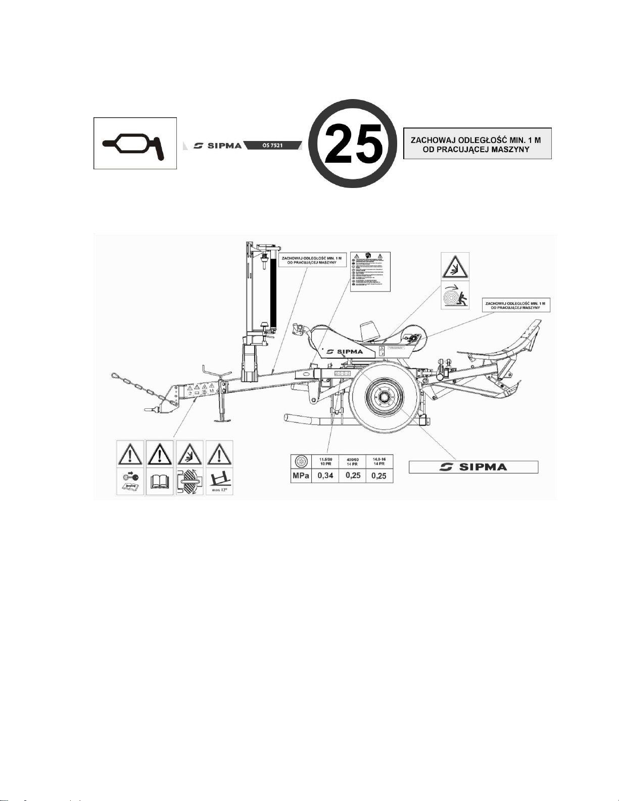
Fig. 20. Location of warning signs on the machine .....................................................................13
Fig. 21. Location of warning signs on the machine .....................................................................13
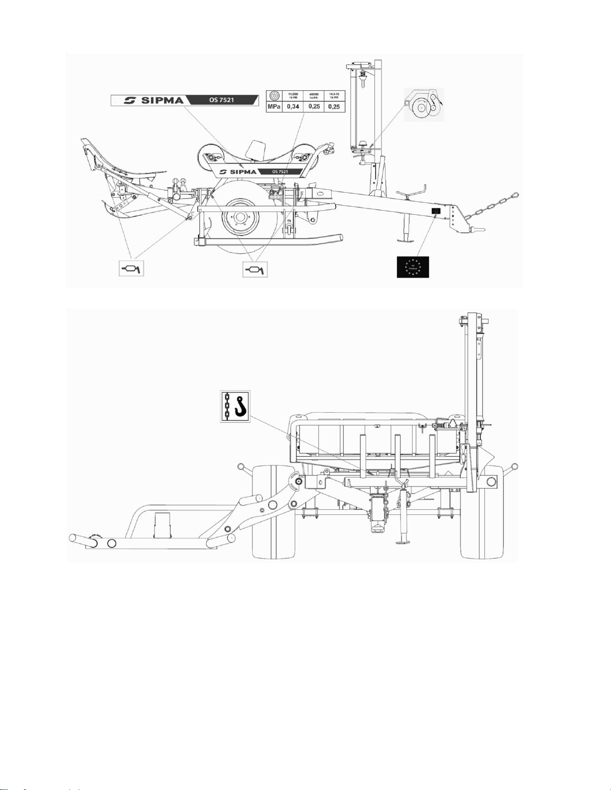
Fig. 22. Location of warning signs on the machine .....................................................................14
Fig. 23. Location of warning signs on the machine .....................................................................14
Fig. 24. Location of markings .......................................................................................................15
Fig. 25. General view of thebale wrapping machine SIPMA OS 7520........................................18
Fig. 26. Belts adjustment................................................................................................................19
Fig. 27. The bale wrapping machine in transport position...........................................................24
Fig. 28. Diagram –connecting the control system with the hydraulic system.............................24
Fig. 29. Connection of the hydraulic hoses to the tractor.............................................................26
Fig. 30. 750mm film installation ..................................................................................................27
Fig. 31. Changing the transmission ratio on the drive roller........................................................29
Fig. 32. Working position –approaching with the tractor to the bale ..........................................30
Fig. 33. Bale wrapping .................................................................................................................30
Fig. 34. Bale unloading on its side ...............................................................................................31
Fig. 35. Bale unloading on its bottom...........................................................................................32
Fig. 36. Bale damper in upper position (prepared for tipping bales on bottom)…........................33
Fig. 37. Bale damper in bottom position (prepared for tipping bales on side).............................33
Fig. 38. Lubrication points in the bale wrapping machine SIPMA OS 7520 .............................36

6
1. INTRODUCTION
The user receives this manual attached to a bale wrapping machine upon sale. The user is
obliged to read the manual thoroughly.
1. The bale wrapping machine with bale damper system SIPMA OS 7520 can be operated
and exploited only by persons who carefully got acquainted with the content of the
Operator’s Manual, and particularly with the information given in the chapter
“Operation safety and warnings”. The same obligation refers to the persons performing
repairs. Not conforming to the principles of the proper operation may be a cause of
accident or damage of the machine.
2. The Manufacturer provides a complete bale wrapping machine with Operator’s Manual, Spare
Parts Catalogue, warranty card and spare parts specified in the chapter “Equipment”. Upon
receipt of the machine, you should check all the received documents and make sure that the
number of the bale wrapping machine on the manufacturer’s plate corresponds to the number
in the documents.
3. The bale wrapping machine is equipped with side safety reflectors which should be connected
to the tractor during the transportation on the public road. Before entering any public road, the
warning triangle must be placed at the socket which is placed on the bale damper of the bale
wrapping machine. It should be taken out before the field operation.
4. Hydraulic hoses should be replaced after 5 years following the purchase of the machine. For a
detailed description of the hoses, see the Spare Parts Catalogue.
5. The manufacturer does not permit any unauthorized changes in the construction of the bale
wrapping machine. Any proposals of changes or improvements should be directed and
consulted with the construction department or the manufacturer's technical service.
The introduction of any changes without prior agreement exempts the manufacturer from
liability for any incidents resulting from such introduction and results in the termination of the
warranty.
6. Use and operation of the bale wrapping machine that does not conform to the Operator’s
Manual exempts the manufacturer from liability for any incidents resulting from improper use
and results in the termination of the warranty.
7. If there is any doubt connected with operating the bale shredder you should direct the questions
to the supplier or maintenance service of the manufacturer to receive comprehensive
explanations.

7
2. OPERATION SAFETY AND WARNINGS
Observe general operation safety rules for mechanical equipment during operation, road
transportation, maintenance and repair works of the bale wrapping machine.
NOTE:
This danger warning symbol indicates important information on dangers
specified in operation manual. When approaching the symbol, beware of dangers
and read thoroughly any relevant information and inform the other operators.
NOTE:
This manual is included in the basic machine equipment. It should be kept during the
whole period of the machine use. In case of sale or handing the machine over to another
user, always include the manual. In case of the manual loss or damage purchase a new copy
by ordering it at the seller.
NOTE:
The manufacturer bears no liability for any accidents resulting from lack of
observance of rules concerning the machine operation safety.
NOTE:
Prior to commencement of any operation,repair or adjustment works on the wrapping
machine, turn off the motor and take the key out of the ignition switch. The whole
machine-tractor combination must be protected against accidental movement..
1. The wrapping machine can be operated and prepared for operation only by adult persons with
tractor driving license and trained in agricultural equipment operation safety. It is forbidden to
operate the machine by persons under the influence of alcohol or other intoxicating substances.
2. Prior to commencement of any operation, repair or adjustment works on the wrapping machine,
if it is connected to the tractor’s hydraulic system, the motor should be turned off and the key
should be taken out of the ignition switch. These operations can be performed only when the
machine assemblies have been protected against accidental dropping.
3. It is forbidden to operate the wrapping machine by children and juveniles.
4. Wear protective gloves during direct operation on the machine.
5. Prior to the machine start-up and during its operation, make sure if there are no persons, in
particular children, in danger zones (in the vicinityof rotary table with wrapped bale and during

8
unloading bales at rear of the machine). It is forbidden for third persons, in particular
children, to be present at the wrapping machine under operation or repair.
6. Pay particular attention during loading bales on the wrapping machine and during their
unloading due to their substantial weight.
7. Danger spots have been labelled by yellow safety signs and warning symbols on the wrapping
machine. The meaning of individual symbols is specified in chapter “Safety Signs”. Familiarize
with the meaning of all presented symbols. Pay particular attention to these symbols during the
machine operation.
8. Prior to each use of the wrapping machine, check its technical condition, in particular the correct
attachment of the wrapping machine to the tractor, technical condition of the hydraulic system,
condition of protective shields etc.
9. It is forbidden to work without the protective shields. It is also forbidden to work with damaged
shields.
10. Prior to electric welding, disconnect the cable from alternator and battery in the tractor.
11. Do not take other persons into the tractor with you. It is also forbidden for the persons to be
present on the machine during its operation and transportation.
12. Do not wear loose clothing which might get caught by the machine operating parts.
13. For the period of transportation on roads, turn off the electronic controller and oil supply.
14. It is forbidden to transport bales on the wrapping machine on public roads.
15. Prior to commencement of drive check the tractor’s brakes operation and its environment. Make
sure there are no third persons (children) in invisible spots.
16. Never leave the tractor’s seat during the drive.
17. Pay particular attention during transportation of the wrapping machine on public roads, observe
traffic rules in force in a given country. Do not exceed the transportation speed limits.
18. Adjust driving speed to existing conditions. Pay particular attention when driving the
machinetractor set downhill and on bends. Never perform anyabrupt turns. Always reduce your
speed in such circumstances.
19. Pay particular attention for location of the tractor with the wrapping machine during bales
wrapping on inclined ground. Always reduce your speed in such circumstances. Never turn off
the clutch nor change the gear into an idle gear on inclinations. It is forbidden to work on
inclinations of more than 12°.

9
20. The wrapping machine with a bale behaves as ballast and changes the way of the set driving
and the tractor’s turning and braking ability. Make sure that the driving and braking is not
limited. Do not neglect the machine mass inertia –consider the adjustments upon turning,
slowing down and stopping. Remember that reactions of the machine with a bale can change
its drive course.
21. Operation of the controller (control panel) can be performed only from seating position in the
tractor cockpit.
22. The machine-tractor combination must absolutely be protected against accidental start-up by
third persons, in particular by children.
23. Hydraulic system hoses must be connected to and disconnected from the tractor after prior
pressure relieve in the installation.
24. The hydraulic system operates with very high pressure. During leak tightness check, make sure
to use appropriate protective equipment (e.g. cardboard protection) in order to avoid the risk of
injury. There is a risk of infection in case of skin puncture –contact medical assistance
immediately.
25. All elements under stress (springs) and elements collecting energy (gas springs) are very
dangerous. Pay particular attention in their operational zones. Replace only with the producer’s
original spare parts.
26. Connecting the machine to the tractor must be performed with extra care. During reversing it
is forbidden for any third person to be present in the area between the reversing tractor and the
bale wrapping machine.
27. Do not perform any work on the hydraulic system by yourself if you do not have practical
knowledge in this field and if you are not sure about your abilities. Such operation should be
performed by experts.
28. Do not enter the area between the tractor and the machine until the combination has been
protected against sliding by pulling the hand brake or placing wedges under the tractor’s driving
wheels.
29. Check pressure in tires on regular basis. Overpressure can cause their fracture (risk of
explosion).
30. Make sure you know how to perform emergency stopping of the wrapping machine and the
tractor.
31. Pay particular attention during wrapping misshaped bales as they can fall from the turning table
during the operation. It is also forbidden to wrap bales of diameter exceeding the value of
diameter specified in the Operator’s Manual.

10
NOTE:
Start-up of thetractorandbale wrappingmachine motor canbeperformed onlyafter
having checked that turning on the drive to the wrapping machine turning frame is
free of any risk. Protect the machine against access of the third persons (especially
children) and animals.
NOTE :
Pay particular attention operating on cut and hold system with sharp film cutter.
Insufficient care may result in hands injury.
2.1. Fire regulations
1. As the wrapping machine works with flammable materials fire regulations must be absolutely
observed and the occurrence of fire during its use must be eliminated. It is recommended to
equip the wrapping machine (tractor) with operating powder fire extinguisher (BCE type) prior
to leaving for field.
2. Prior to commencement of works lubricate the wrapping machine in accordance with
lubrication schedule and then start-up the machine checking if its moving parts do not rub
against its fixed parts. All detected reasons of rubbing of mechanisms in the machine must be
removed prior to its operation.
3. It is forbidden to smoke and use open fire in the vicinity of operating wrapping machines.
4. It is forbidden to conduct repairs, in particular welding works without prior cleaning the
machine of the residual material which might cause fire. Before welding works commencement
electric cables, hydraulic ducts, bearings and sleeves plastic casings must be protected against
damage.
Dear User, remember that:
Labour safety and hygiene requirements, traffic regulations and fire regulations
must be absolutely observed.
2.2. Description of residual risk
The biggest risk results from presence of third persons, in particular children, in the vicinity
of operating wrapping machine. The machine should be protected against access of unauthorised
persons (in particular children) and animals.
Neglecting the provisions of this instruction and warning labels results in risk increase, in
particular upon:
Approaching the machine under operation;
Touching the unshielded cutter;

11
Operating the wrapping machine on inclinations;
Checking mechanisms during operation;
Failure to adjust speed to field conditions and road conditions and failure to consider the
mass of the machine with a bale during turning and driving uphill.
2.3. Evaluation of the residual risk during the machine operation
Upon observance of the Manual provisions and in particular upon:
Thorough reading of operation manual;
Forbidding third persons to approach the wrapping machine under operation;
Forbidding children to approach the wrapping machine under operation;
Operating the wrapping machine only in accordance with its intended use;
Wearing only skin tight clothing (without loose parts);
Operating the wrapping machine only by an operator who has thoroughly read the
operation manual and safety regulations;
Protecting the machine during repairs and everyday operation;
Paying special attention during driving with loaded bale across the field and during
transportation of the empty wrapping machine along public roads
residual risk is reduced to minumum.
2.4. Safety signs
Extremely dangerous spots have been marked on the machine with yellow safety signs and
warning symbols. The user must be thoroughly familiarized with the meaning of the following
signs and follow the given instructions. During operation pay particular attention while present in
the direct vicinity of spots marked in such manner on the machine.
NOTE:
Warning labels must always be legible. In case they are illegible or damaged, they
should be purchased at SIPMA SA sales points as spare parts and be replaced.
The meaning of symbols located on the machine is presented below:
NOTE:
Residual risk can be caused by inadequate knowledge of specified warnings and
instructions and failure of their observance!

12
Fig. 1. Obligation to read
Fig. 2. Attention: Danger Fig. 3. Attention: moving Fig. 4. Keep a safe distance
the content of the
Operator’s Manual of hand injury bale from the machine
Fig. 5. All repairs and
Fig. 6. Stand clear from the Fig. 7. Do not operate on Fig. 8. Danger of burns by
adjustments on
disconnected machine area of the joint hitches slopes of more than 12° a hot oil
Fig. 9. Do not operate the machine Fig. 10. Information pictogram Fig. 11. Tire pressure until you have
read the Operator's Manual
Fig. 12. Film routing in the Fig. 14. Direction and Fig. 15. Information
Fig. 13. Lifting lug
13
film dispenser number of turns pictogram
Fig. 16. Grease Fig. 17. Information Fig. 18. Admissible Fig. 19. Information pictogram
lubrication point pictogram transport speed
Fig. 20. Location of warning signs on the machine
14
Fig. 21. Location of warning signs on the machine
Fig. 22. Location of warning signs on the machine

15
Fig. 23. Location of warning signs on the machine
3. MACHINE IDENTIFICATION
1 -manufacturer’s plate 2 –
serial number
Fig. 24. Location of markings
Manufacturer’s plate is located on the main frame beam on left side of the machine. The
wrapping machine’s serial number is located under the manufacturer’s plate (see Fig. 24).

16
4. MACHINE DESIGNATION AND GENERAL INFORMATION
Bale wrapping machine with bale damper system SIPMA OS 7520 is designated for
wrapping individual bales of semi-dry hay of grasses and papilionaceous plants of humidity ca 60%
harvested with round balers. Bales, after wrapping with special, spreading self-adhesive film are
intended for hay-silage making. The machine is designed for wrapping bales with film.
Occasional transportation across fields and on roads is also considered as operations
accordant to the designation. Using the bale wrapping machine for other purposes is considered as
operation incompliant with its intended use. Meeting and strict observing the conditions of the
machine’s exploitation as well as operation and repairs according to the requirements given in the
Operator’s Manual is also an integral part of the intended use of the machine
The manufacturer bears no responsibility for any damages or loses resulting from the
machine operation not according to its aforementioned intended use. The results of the
machine misuse are the sole responsibility of the machine owner and/or its operator.
The machine should be used, operated and repaired only by persons familiar with its
detailed characteristics and rules of proceedings in the scope of safety
Regulations on accidents prevention and all basic labour safety and hygiene regulations, as
well as traffic regulations must always be observed
The introduction of any changes without prior agreement exempts the manufacturer from
liability for any incidents resulting from such introduction.
The bale wrapping machine is the attached machine and can operate on field loading bales
without the necessity for other equipment. The wrapping machine is suited for cooperation with
agricultural tractors of motor power exceeding 35 kW and with two external hydraulic system
sockets. The wrapping machine can wrap bales of 1.2m width; 1,2 ÷1,5m diameter and weight of
up to 1000 kg. Special film should be used for bale wrapping; it can be purchased at the suppliers.
The manufacturer of wrapping machines is not responsible for any loss resulting from the
use of incorrect film.
Preparation of hay-silage in the form of cylindrical bales wrapped with film allows for
significant reduction of nutritive substances loss in comparison with traditional methods of hay
making and current methods of silage making in prisms and vehicular silos.
Mowing of grasses, mixtures and papilonaceous plants intended for hay-silage (for
wrapping) should take place in the initial stage of plants coming into ear at the highest content of
nutritive substances (preferably in the afternoon). Harvesting of the mowed material with round
balers should take place several dozen hours of initial drying (depending on atmospheric
conditions) i.e. practically the next days after mowing. The bales should be very tightly rolled
(pressed) so that the volume of air (oxygen) inside is reduced to its absolute minimum.
After baling with round balers the bales should be wrapped with film bywrapping machines
as soon as possible; no later however than within two hours after the baling. If the green forage
bales are left for longer period without being wrapped with film, it can result in commencement of
disadvantageous putrefaction processes.
Wrapped bales should be placed in the farmyard for the minimum period of 6 ÷8 weeks in
dry place on smooth surface. During this time fermentation process takes place. The process should
take place in temperatures above zero. Make sure that film on the bales is not damaged. Damaged
places should be again covered with film.

17
The bales should be placed vertically one on the other –in two levels at most. Two months
after harvesting silage is ready for feeding as fully valuable food.
5. TECHNICAL AND OPERATIONAL SPECIFICATIONS
Dimensions:
•length
•height
•width
•weight
-
-
-
-
4,60 m (in the transport position)
2,39 m (in the transport position)
2,65 m (in the transport position)
1550kg
Dimensions of the wrapped bales:
•diameter
•length
•weight
-
-
-
1,2 ÷1,5 m
max 1,2 m
max 1000 kg
Dimensions of tires:
-
400x60-15,5
Pressure in the tires:
-
0,25MPa
Tractor requirements:
-
power of more than 35 kW
Drive of the machine:
-
hydraulic motor SR200,OMR200
Min. capacity of the tractor’s hydraulics:
-
20 l/min
Max. capacity of the tractor’s hydraulics:
-
50 l/min
Max. pressure of the tractor’s hydraulics:
-
16 MPa
Nominal electric power:
-
12V
Minimal number of film layers:
-
2x (double counting with the overlaps)
Type of film for wrapping:
-
special polyethylene film of 0,025 ÷0,03
mm thickness in various colours
Dimensions of roll with film:
-
film rolled on a sleeve of ø 76 mm hole
diameter
Width of the film:
-
500 mm, 750 mm
Max. diameter of roll with film:
-
260 mm
Film cutting:
-
Automatic cutting with a knife in the cutand-
hold assembly
Operation of the bale wrapping machine:
Steering
-
one person (tractor’s operator)
control levers

18
The value of the noise emitted by the machine –equivalent of acoustic pressure noise
emission corrected by A factor –below 70 +/- 1.5 dB (A).
6. GENERAL SPECIFICATION AND DESCRIPTION
Fig. 25. General view of thebale wrapping machine SIPMA OS 7520
1 –main frame; 2 –lift arm; 3 –rotary table with tip frame; 4 –film dispenser; 5 –road wheels; 6 –drawbar;
7 –bale damper, 8 –jack stand
The bale wrapping machine with damper system SIPMA OS 7520 consists of the following
assemblies:
Main frame(1)
Lift arm (2)
Rotary table with tip frame
(3) Film dispenser (4) Road
wheels (5) Drawbar (6)
Bale damper (7)
Jack frame (8)
The main frame (1) is connected with the drawbar (6) which the tractor is attached to. The
rotary table with tip frame(3) is fixed to the main frame with two pivots and a hydraulic servomotor.

19
Rotary table with rollers and belts is located on the tip frame. Film dispenser (4) is located on
vertical beam on the left side of main frame.
Lift arm (2) which is used to load bales on the rotary table is fixed to the right side of the
main frame.
The wrapping machine is driven by the hydraulic motor connected to the tractor’s hydraulic
system. The drive from the hydraulic motor is transmitted through a gearbox to the rotary table
which rotates around its vertical axis. Open bevel gear transmits the drive via a shaft and a chain to
a roller with a double sprocket wheel. Belts on the rollers (see Fig. 26 pos. 4), transmit the drive
between the rollers and a bale. In this way the bale loaded on the wrapping machine at each rotation
of the table is turned by belts located on the rollers by a small angle also around its own axis.
Rolling of subsequent film layers on the bale (bale wrapping) is performed as result of combination
of the above described movements.
Correctly adjusted belts should rotate parallelly to the rollers with a bale without the effect
of the bale lateral slide. They should also provide the possibility of a reliable loading and wrapping
of bales with diameters of 1.2 m ÷1.5 m. If necessary adjust the position of the rollers (see Fig.
26) To adjust the position of the rollers, loosen bolts attaching the bearing mount (1), move it
in beans while screwing or unscrewing the bumper bolt (3) making sure each mounting is moved
by identical distance, tighten the bolts (1) and tighten the locknut of the bumper bolt.
1- beans in the rotary table;
2- bearing mount;
3- bumper bolt; 4- belts;
Fig. 26. Belts adjustment
Film dispenser (4) intended for 500mm and 750mm film consists of frame and a support
with aluminium rollers interconnected with each other through a gear. The roller with film is set on
the dispenser according to the drawing (see Fig. 30). Properly selected transmission ratio between
aluminium rollersand tight clinging ofthe film to the rollers provide its spreadingand tight clinging
to subsequently wrapped layers on a bale. The film spread degree can be adjusted and should be ca
60%.
Hydraulically driven cut-and-hold system is located in the rotary table. It is used to keep
holding the film during the first two rotations of the table. After two rotations the film is
automatically released.
The main frame (1) is connected through a hydraulic cylinder with the tip frame. The
extending cylinder lifts the tip frame for bale unloading. When it returns it lowers the tip frame to
its position on main frame (horizontally). Only then the wrapping process by rotation of the rotary
table with a bale can take place.

20
Cut-and-hold system with a blade is located in the rotary table. The film, pulled from the
dispenser is stretched on a roller of the cut-and-hold system, held between rubber discs and cut off
with a blade.
Resistance cones are located on horizontal beams of the rotary table to protect bales against
sliding off belts during wrapping.
The bale damper system (7) is attached to the rear side of the main frame. Depending on its
setting it can be used for positioning bales on their sides (bale rolled off on the field) or for
positioning bales on their bottom (bale’s drop surface is moved during its hydraulically controlled
unloading).
During transportation of the wrapping machine on public roads place the warning triangle
in the socket located on the damper system.
The wrapping machine is equipped with a jack stand (8) which stand on the ground during
the machine storage –vertical position (see Fig. 24). During the machine operation and
transportation, the support should be rotated by 90°and protected with a pivot in this position,
check its position from tractor’s seat.
The bale wrapping machine SIPMA OS 7520 is equipped with an electronic controller
which controls basic machine functions and provides the operator with necessary information of
the machine operation. The operation manual ofthe controller is presented below. The control panel
should be located in a visible place in the tractor’s cabin. Supply plug should be connected to
operating lighter socket in the tractor and the control panel should be connected with indirect wire
to a collector located on the wrapping machine. The controller description is presented further in
this manual. Remember that the control panel is not waterrproof.
6.1. Sensors.
In order for the controller to perform correctly all functions in all operating modes (see the
description below) the sensors must be short-circuited by magnets’ magnetic field. Thus the sensors
must be mounted at a correct distance (appr. 15 mm) from magnets. In case the magnetic field does
not influence the sensor, adjust the sensor position against the magnet position.
The wrapping machine has 7 sensors and 3 magnets:
a) 2 sensors of the tip frame cooperating with 1 magnet (in case of incorrections of the tip
frame movements, adjust the position of the sensors in bean openings)
b) 1 sensor of the lift arm cooperating with 1 magnet placed on the arm (indicating the bale on
the arm ready to be lifted)
c) 1 sensor of the bale damper cooperating with 1 magnet (controlling the movement of the
bale damper)
d) 2 sensors of the angle position (the first one is responsible for the correct position of the
rotary table for the bale loading and the correct position for the bale unloading; the second
one supervises the position of the lift arm
e) 1 reed relay sensor of the film dispenser (responsible for signalization of correct film
feeding)
In case any sensor is damaged it is possible to verify its condition on the control panel (see
“Sensors status”). If the sensor is damaged, it should be replaced.
Table of contents
Other Sipma Farm Equipment manuals

Popular Farm Equipment manuals by other brands


Degelman
Degelman 7900 Series Operator's Manual/Parts Catalog

First Products
First Products SEEDA-vator SE60 Operator's manual & parts list

Woods
Woods TURFKEEPER TK60.20 Operator's manual

Krone
Krone Swadro 1000 Original operating instructions

MacDon
MacDon FlexDraper FD2 Series installation instructions

Monosem
Monosem EXTEND 4 RANGS user manual


