manuals.online logo
Brands
  1. Home
  2. •
  3. Brands
  4. •
  5. Rain-Flo Irrigation
  6. •
  7. Farm Equipment
  8. •
  9. Rain-Flo Irrigation 2670 User manual

Rain-Flo Irrigation 2670 User manual

MODEL 2670
RAISED BED PLASTIC MULCH LAYER
OPERATING
MANUAL
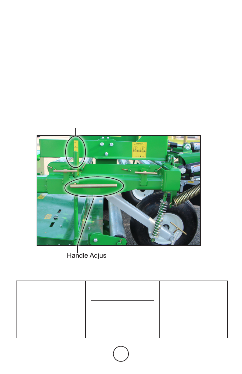
Bed Height. . . . . . . . . . . . . . . . . . . . ............6
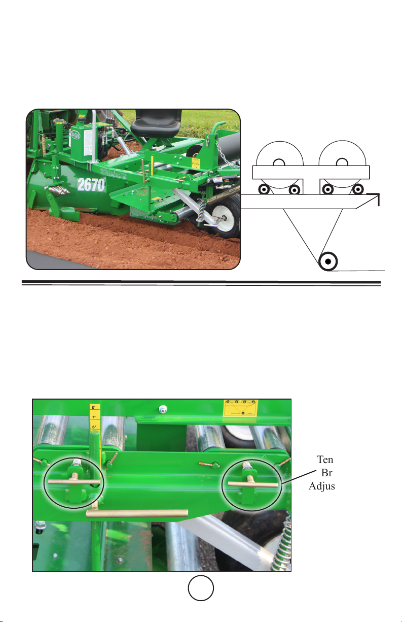
Bed Press................................7
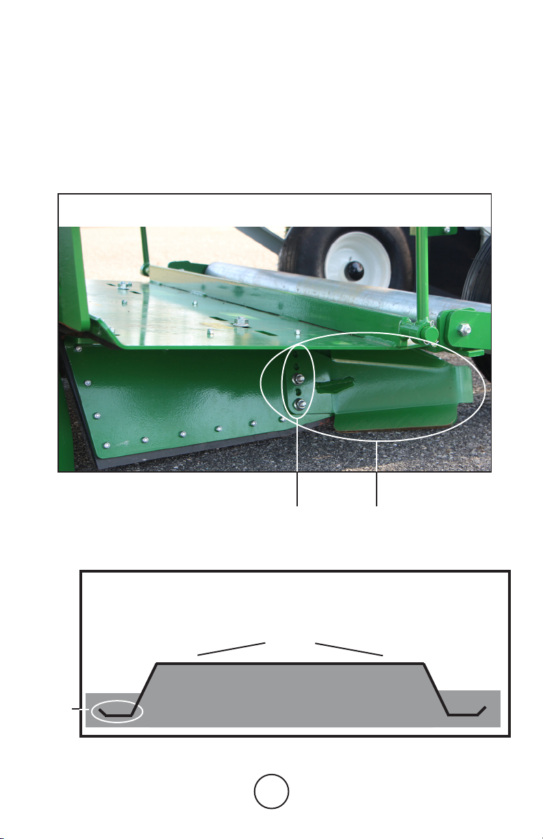
Bed Width . . . . . . . . . . . . . . . . . . . . ............7
Cover Disk . . . . . . . . . . . . . . . . . . . . ..........11
Dirt Shield...............................11
Drip Irrigation Attachment . . . . . . . . . . . . . . . . . . 15
Drip Tape Down Pipe ......................15
Features .................................4
Getting Started .. . . . . . . . . . . . . . . . . . . . . . . . . . . 5
Helpful Tips..............................30
Options ..................................4
Parts Breakdown, Descriptions ...........24-28
Parts Breakdown, Exploded Views.........17-23
Plastic Rolls, Installing ......................8
Plastic Tensioning . . . . . . . . . . . . . . . . . . . . . . . . . 8
Plastic Width. . . . . . . . . . . . . . . . . . . . .........16
Preparation Of Soil . . . . . . . . . . . . . . . . . . . . . . . . 4
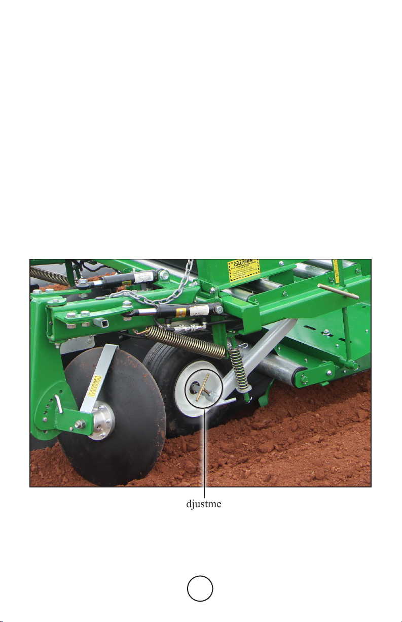
Press Wheel . . . . . . . . . . . . . . . . . . ...........9
Ro-Trak, Maintenance. . . . . . . . . . . . . . . . . . . . . 14
Ro-Trak, Sensor. . . . . . . . . . . . . . . . . . . . . . . . . . 13
Ro-Trak, Trouble Shooting ..................14
Safety First ...............................3
Side Shovel. . . . . . . . . . . . . . . . . . . ..........12
Trench Opener . . . . . . . . . . . . . . . . ..........10
Trouble Shooting. . . . . . . . . . . . . . . . . . . . . . . . . 31
Warranty . . . . . . . . . . . . . . . . . . . . . . . . . . . . . . . 30
2
Table Of Contents
No riders beyond the speed of 3 MPH. Make sure you read and
understand all the precautions.
Keep people away when lifting and lowering the machine.
Be careful when turning around; machine is 8’ long.
Do not crawl under the machine when lifted.
Cover discs are sharp; stay clear.
Do not adjust the machine when it is moving.
Do not stand on machine.
Do not sit on machine except designated seat.
Tractor operator is responsible for extra worker(s) around machine.
Rain-Flo is not responsible for accidents if any should occur.
3
!
!
!
!
!
!
!
!
!
!! Safety First !!
!
Soil Preparation
4
* To build a uniform rm bed with no hollow spots, soil has to be
prepared properly.
* All soils are different. Some (moist, sandy) soils make nicer square
beds than others. You need to know what soil preparation works
best with your soil.
* Machine performs the best if soil is plowed 6” to 8” deep.
* Soil should be harrowed or roto-tilled until free of sod lumps.
* Proper moisture in soil is important to form nice rm beds. For
best results, soil should not be powder dry or in muddy condition.
2670 Features
Options
• Automatic Self Steering Ro-Trak for Hill Sides
• Single or Double Drip Tape Attachment
• Hydraulic Cover Disk Adjustment
• Crowned Bed Press for Level Fields
• Center Fillers; to Help Fill Center of Bed
• 400 lb. Ground Driven Dry Fertilizer Hopper
• Fumigation Tank Mounts with Gas Knives
• 80 HP FWD Minimum Tractor Size
•
Minimum Row Centers; 54” with 3’, 64” with 4’ or 74” with 5’ plastic
• Adjustable Plastic Width from 3’ to 5’
• Adjustable Bed Height from 5” to 9”
• Adjustable Tension Brake on Plastic Roll Carriers
• Adjustable Row Markers
• Operator Seat
• Replaceable, Reversible Plow Share Blades
• UHMW Plastic Lined Bed Press
• Bed Press has adjustable side press plates, for More or Less
Plastic Coverage
• Quality Powder Coated Paint
5
Getting Started
Before laying plastic, you may want to try out the machine making beds
only; to get the feel of the machine.
Adjust 3-point top link on the tractor to level the machine.
Let the machine down fully and regulate the amount of soil in front of the
machine with the length of the 3 point top link.
It is not necessary to pull more soil than needed to ll the bed. Pulling too
much soil may cause tractor slippage, resulting in side drifting.
To get a higher, rmer bed, grower may want to pre-bed (make beds
without laying plastic) then come back to lay plastic mulch. This will also
help remove shallow spots in the bed. Disk blades can be removed when
making beds only.
4” ............20”
6” ............16”
8” ............12”
Bed Height Adjustment
Bed height is adjusted by lifting and lowering the bed press. Use label ruler
behind pin indicator (top of pin) located on both sides of the machine to
determine bed height(See below).
To adjust bed height, release the lock handles. Raising the bed is done by two
people lifting the deck by hand, or by slowly driving forward with the 3-point
hitch in the down position; the soil will lift the bed press. To lower the bed,
slowly lift 3-Point hitch with the tractor to the desired height and lock the
handles.
If your bed is not rm and has shallow spots in the center, add weight on the
bed press, adjust the top link, and/or install the optional center of bed llers.
Lock Handle Adjustment
Important: When bed height is adjusted, bed width (Page 7)
and trench openers (Page 10) need to be adjusted accordingly.
3 Ft. Plastic
Bed Height Bed Width
4 Ft. Plastic
Bed Height Bed Width
4” ...........30”
6” ...........26”
8” ...........22”
5 Ft. Plastic
Bed Height Bed Width
4” ...........40”
6” ...........36”
8” ...........32”
6
Bed Height Indicator
Bed height and bed width can be adjusted between the above chart indications.
7
Bed Width Adjustment
Adjustable Side Plates
The bed press has adjustable side plates (photo at bottom). These
must be adjusted according to bed height by releasing the bolt and
sliding the side plates in or out at the slot. Make sure bolts are tight
to keep them from slipping. For setting, follow chart on machine or
on Page 6. It is important to maintain enough plastic at the edge for
proper coverage.
NOTE; For straight beds, each side must be equally adjusted.
Adjustment Slot
for Side Plates
8
Plastic Tension
Plastic rolls have a tension brake. Just a slight tension is needed.
Tension
Brake
Adjustment
Note; Setting brake tension too tight may affect the performance of
the machine and can cause plastic to pull out from under press tires.
Installing Plastic Rolls
To install plastic rolls, place them on top of rollers (A). Pull end of plas-
tic down in between rollers and underneath bottom roller (B). Secure
plastic and drip tape at end of row. Only feed from one roll at a time.
AA
BB
Plastic
Roll
Plastic
Roll
Plastic
End ViEw
9
Press Wheel Adjustment
Press wheels need to run at the bottom of the trench and not
on the side to stretch the plastic properly. To adjust, loosen
T-handle and make in or out changes as needed.
Tilt the front of the press wheel on an inward angle to stretch
the plastic.
Use only high quality plastic to avoid straight line tear.
Adjustment
Setting
10
Trench Opener Adjustment
IMPORTANT!
Adjust machine so that 5” of plastic is covered on both sides
5”
Plastic
5”
Trench openers are to cut a trench along the sides of the bed. This
will give a ‘cup’ at the edge of the bed to prevent the plastic from
blowing off. If bed height is adjusted, the trench opener has to be
adjusted accordingly.
Plastic
“Cup”
Raised Bed
Trench
Opener
Depth
Setting
11
Cover Disk Adjustments
Cover disks and dirt shields are marked right and left side (stand-
ing in back). Install shields as marked, with snap pin towards the
center of the bed. Set disks on a 45 degree angle; make in or out
adjustment as needed. For more or less coverage, tilt disk forward
or backward as decal shows (pictured at bottom).
In some sandy soils the disk blades can be laid in a atter position
and turned at a 45 degree angle. However, if it does not cover the
plastic properly, the disks need to be set more upright or tilted back.
Angle
Adjustment
For More or
Less soil.
Left to
Right
Setting
Angle
Adjustment
Dirt Shield
Adjustment
12
Side Shovel Adjustment
Notice the
amount of soil
side shovel is
loosening for
cover disk.
Depth
Adjustment
The side shovels are used to loosen more soil for the cover disks. Adjust
so that the shovel is approximately 1” to 2” below bed formers.
Adjust shovel shank in or out so they are in line with cover disks.
13
Ro-Trak Sensor
AUTO RO-TRAK
*Ro-Trak has the most benets on hillsides and contours.
*Automatically steers to correct machine side drifting.
*Ro-Trak is activated by a sensor at the back of machine.
Helpful Tips
*When installing Hyd. pump, lead hoses through 3-Point A frame.
*Inspect and make sensor square to machine.
*Twelve volts can be supplied by tractor or a separate battery.
*Ro-Trak requires only low RPM PTO speed to function.
*Hollow bed can effect Ro-Trak performance.
*If machine has been setting for a period of time, it may be
necessary to manually move the valve spools to get oil through
the system.
*With PTO pump running, use a Phillips screw driver and push
the silver tip of the spool inward approximately ¼” (Page 14.)
*Manual Ro-Trak is operated with tractor Hyd. and must be
steered by tractor operator.
Sensor Wire Plug
(Behind bar)
Micro switches
to change
sensitivity.
Use square
when bolting
sensor arm to
machine.
Transport
disable
switch
14
Ro-Trak not functioning? Check for these problems.
1. Is the PTO engaged?
2. Is a 12 volt battery properly connected?
3. Is the sensor at rear of machine plugged in?
4. Check oil level.
5. Check for any damaged hoses or wires.
6. Is sensor lifted 3” or more? (Sensor has transport cut off switch).
7. Do the indicator lights on solenoid light-up?
8. If indicator lights light-up and Ro-Trak doesn’t function, push in
silver pins on solenoid spools (approximately ¼” on either side).
9. If indicator lights do not light up, undo plate on top of solenoid
and check for loose wires.
10. Steers only one way? Change bad steering switch in sensor.
11. Call Rain-Flo at (717) 445-3000.
Hyd. Oil Level
Solenoid Valve
Auto Ro-Trak
1. Periodically check oil level. Low oil level may cause air
to come into the system and effect Ro-Trak performance.
2. Change oil and lter every 200 hours or 3 years (ISO 46 Hyd. Oil).
3. Check for any damaged hoses or electric wires.
Maintenance
Valve
Spools
Silver Tip
Indicator
Lights
Valve
Spools
Silver Tip
Drip Irrigation Roll Carrier
15
Drip Irr. Tape Placement
Slide drip roll onto roll carrier rod so
that drip emitter will be turned up toward
plastic (for less clogging).
Feed drip tape through the rst guide
on the swing arm and through the second
guide that’s bolted on the drip roll carrier
frame. (See Sketch Below.)
NOTE;
Make sure
drip roll is
compressed rmly
between plates
for positive braking effect.
Feed drip line through the
guides on the spool carrier and
into the drip line down pipe.
To avoid damaging drip tape
with the press pan, adjust top
of down pipe about 1” to 2”
below the plastic mulch.
Turn drip emitters up toward
the plastic for less clogging.
Drip Tape
Guides /
Rollers
Drip Line
Down Pipe
CHANGING THE PLASTIC WIDTH
The Model 2670 will lay 3’, 4’, or 5’ wide plastic.
To make these adjustments, release the lock bolts at front end of bed shapers
(No.1) photo. Remove bolts at back end of bed former (No.2) photo and slide
to appropriate setting. Make sure bolts are tight.
Adjust bed press side plates; remove bolts from bed press side plates
and move to appropriate setting (No. 3) photo.
Adjust roll carrier; loosen bolts and slide bracket so plastic roll ts between
bracket (No.4) photo. Adjust approximate 1½” wider than plastic width.
(No.1) Lock bolt (No.2) Remove bolts on
back side of bed former
16
(No.3) Remove bolts from bed press
side plates and move to appropriate
setting. NOTE; For straight beds,
each side must be equally adjusted.
1
2
3
(No.4) Plastic Width
Adjustment
PLASTIC WIDTH
5FT 4FT 3FT
17
Complete Top
Drip Roll Carrier
#1A
#1D
Complete Double
Top Drip Roll Carrier
Complete Bottom
Drip Attachment
#118A 121
2670
Complete Double
Bottom Drip Attachment
#118D
135
592 70
70
120 118
134
151 152
6”
5”
Bed
Hight
153
156
3
’-
--
5
‘
-
-
-
4
’
P
last
ic Wi
d
th
A
dj
us
t
m
ent
S
er
i
a
l
Nu
m
be
r
186
Rain-Flo
Irrigation
WhenQuality counts
155
159
Use
Sway Bars
Optional
Center Fillers
158
Use TopLink to
Level Machine
FIL
176
177
Operating
instructions
Operating
instructions
Operating
instructions
Feed
H
ose
s
4”
3”
2”
1”
Flo
Layer
Rain-
Plastic Much
2670
150
19
Figure 1
2670
11
3B
3E
3A
8B
10
3D
22
54
10
7
72A
9
72A
2
1
885
89
89
885
3-P
5A
8
8F
8E
8E
8C
49
150
6B
427
192
150
148
150
192
427
8C
201
19
6
3C
6C
Use TopHole
For Higher Lift
Keep Machine
Full of Soil
18
14
16
15
18
20-70R
21
22-70L
23 22-70R
Figure 2
2670
19-70R
18
15C
Crowned
#14A
Complete Teon Kit
(Top and Side Teon)
14, 16, 19R, 19L, 21
#19A
Left and Right Side
Teon Only
19R, 19L, 21
Complete Side Plate
with Teon
17, 19R, 20R, 21
#20-70CR
#15A
Complete Flat Bed Pan
With Out Bottom Roller
14, 15, 16, 73, 74
74
A
d
j
u
s
t
167
175
F
ee
d
P
l
as
tic
196
196
147
58FN
19
17 17
20-70L
19-70L
19
24
34
34
41
41
35 36
36 56
37 38
40
56
41
41
Figure 3
2670
9
2670
151 152 153
Use TopLink to
Level Machine
FIL
156
3
’-
--
5
‘
-
-
-
4
’
P
last
ic Wi
d
th
A
djust
m
ent
155
Notice
No Seatbelt
160
End Veiw of
Plastic Roll Holders
161
176
159
Use
Sway Bars
Optional
Center Fillers
158
170
177
Rain-Flo
Irrigation
Feed
H
ose
s
186
S
e
r
i
a
l
Nu
m
be
r
Operating
Instructions
Operating
Instructions
Operating
Instructions
Rain-Flo
Irrigation
When Quality Counts
S
h
o
v
e
l
H
o
l
d
e
r
6”
5”
Bed
Hight
4”
3”
2”
1”
Flo
Layer
Rain-
Plastic Much
2670
150
19
150
Operating Insructions
176
29-70R
33-70
33-70
29-70L
30-70 30-70
19
3816
123C
123C
150
150
27
70
381C
25-70
25-70A
Use TopHole
For Higher Lift
Keep Machine
Full of Soil
20
111386
Hub Complete w/ Bolts
#71
Figure 4
2670
62A
62B
#66-70CR
#50
Complete Wheel Only
(#50 - 54, BB-1)
67 62
68
334
422
423
72
50
53
54
1
54
61
62
67
68
63-70
63A
Caution
Disc Blade
157
R
i
g
h
t
S
i
d
e
173R
BB-1
29-70R
47-70
48C-70
46-70
48B-70R
111386
48-70R
57-70R
65-70R
65A-70
60-70A
128BP
SWS
PWS
33-70
42-70R
3411
12612
12SN
34SN
370 370
12612
38134
34214
69A
Flat Plate on
Opposite Side
#61-70CR
Complete Disc Assembly
(#47-70, 48-70R, 48B-70R,
48L-70, 57-70R, 61, 62, 63,
65-70R, 65A-70, 111386)
Dirt Shield Complete
(#60-70A, 66, 69-70,
69A, 70, 128BP, 309A,
358)
#42-70CR
Press Wheel Complete
(#1, 42-70R,
50, 53, 54, 72)
48S-70R
48S
48BF
54
LP-187
70
150
69-70
66
358
309A
34SN
12SN
406
148
150
48BB
65LB
65SB

Other Rain-Flo Irrigation Farm Equipment manuals

Rain-Flo Irrigation 2370 User manual

Rain-Flo Irrigation

Rain-Flo Irrigation 2370 User manual

Rain-Flo Irrigation 2570 User manual

Rain-Flo Irrigation

Rain-Flo Irrigation 2570 User manual

Rain-Flo Irrigation CHALLENGER 1800 User manual

Rain-Flo Irrigation

Rain-Flo Irrigation CHALLENGER 1800 User manual

Rain-Flo Irrigation 1200 User manual

Rain-Flo Irrigation

Rain-Flo Irrigation 1200 User manual

Rain-Flo Irrigation 1670 User manual

Rain-Flo Irrigation

Rain-Flo Irrigation 1670 User manual

Rain-Flo Irrigation 2370 User manual

Rain-Flo Irrigation

Rain-Flo Irrigation 2370 User manual

Rain-Flo Irrigation 2470 User manual

Rain-Flo Irrigation

Rain-Flo Irrigation 2470 User manual

Rain-Flo Irrigation 2400 User manual

Rain-Flo Irrigation

Rain-Flo Irrigation 2400 User manual

Rain-Flo Irrigation 2600 II Series User manual

Rain-Flo Irrigation

Rain-Flo Irrigation 2600 II Series User manual

Rain-Flo Irrigation CHALLENGER 1800 User manual

Rain-Flo Irrigation

Rain-Flo Irrigation CHALLENGER 1800 User manual

Popular Farm Equipment manuals by other brands

Scarecrow SCARECROW 180 User instruction manual

Scarecrow

Scarecrow SCARECROW 180 User instruction manual

waratah HTH616C SIII Operator's manual

waratah

waratah HTH616C SIII Operator's manual

Krone Comprima F 125-1 operating instructions

Krone

Krone Comprima F 125-1 operating instructions

Tanco i73 Operator's handbook

Tanco

Tanco i73 Operator's handbook

Landoll 850 FINISHOLL Series Operator's manual

Landoll

Landoll 850 FINISHOLL Series Operator's manual

Westfield MKX100 SERIES Assembly guide

Westfield

Westfield MKX100 SERIES Assembly guide

LELY ASTRONAUT A3 Next Operator's manual

LELY

LELY ASTRONAUT A3 Next Operator's manual

aivituvin AIR 70 instruction manual

aivituvin

aivituvin AIR 70 instruction manual

STABLE GRAZER GENERATION II installation guide

STABLE GRAZER

STABLE GRAZER GENERATION II installation guide

KUHN GMD800GII-FF Operator's manual

KUHN

KUHN GMD800GII-FF Operator's manual

Betterbee Lyson instructions

Betterbee

Betterbee Lyson instructions

Tatu Marchesan RC2 2600 CL Operator's manual

Tatu Marchesan

Tatu Marchesan RC2 2600 CL Operator's manual

AIMA Zeus user manual

AIMA

AIMA Zeus user manual

Spearhead Outfront Flail 130 Handbook & Parts Manual

Spearhead

Spearhead Outfront Flail 130 Handbook & Parts Manual

Peco ESTATE Series Operator's manual

Peco

Peco ESTATE Series Operator's manual

Spudnik 990 Owner's/operator's manual

Spudnik

Spudnik 990 Owner's/operator's manual

Titan Attachments 155SKIDFLAIL Operator's manual

Titan Attachments

Titan Attachments 155SKIDFLAIL Operator's manual

HE-VA Grass-Roller Operating instructions/spare parts list

HE-VA

HE-VA Grass-Roller Operating instructions/spare parts list

manuals.online logo
manuals.online logoBrands
  • About & Mission
  • Contact us
  • Privacy Policy
  • Terms and Conditions

Copyright 2025 Manuals.Online. All Rights Reserved.