enorossi RR 400 EVO Series User manual

WINDROW ROTARY RAKE
Series RR 400 / 450 EVO
USE AND MAINTENANCE MANUAL
rev 0 - 04/11
Importante:
carefully read use and maintenance instructions
indicated in this manual before starting any type of
intervention (Machinery Directive 2006/42/EC).
RR – EVO
(MOUNTED)
RR – EVO
(PULLED)
ISTRUZIONI
ORIGINALI

rev.0 – 06/05
2
Machinery Directive and Harmonised Standards
Windrow rotary rakes series “RR 400 /450 EVO” have been designed by respecting the
standards described in Machinery Directive 2006/42EC and (for the pull type) in
Directive 94/20/EC. In particular, they comply with the following harmonised Standards:
EN 349: Safety of machinery - Minimum gaps to avoid crushing of human body parts
(1993) + A1 (2008)
EN ISO 4254-1: Agricultural machinery - Agricultural self-propelled, mounted, semi-
mounted and trailed machines. Common safety requirements (2008)
EN ISO 4254-10: Agricultural machinery - Agricultural self-propelled, mounted, semi-
mounted and trailed machines - Safety - Part 10: Rakes and Hay tedder (2010)
EN ISO 11684: Tractors, machinery for agriculture and forestry, powered lawn and
garden equipment - Safety signs and hazard pictorials - General principles (1995)
EN 12100-1: Safety of machinery - Basic concepts, general principles for design - Part
1: Basic terminology, methodology (2003) + A1 (2009)
EN 12100-2: Safety of machinery - Basic concepts, general principles for design - Part
2: Technical specifications (2003) + A1 (2009)
EN 12965: Tractors and machinery for agriculture and forestry. Power take-off (PTO)
drive shafts and their guards. Safety (2003) + A1 (2004) + A1 (2009)
EN 13857: Safety of machinery - Safety distances to prevent hazard areas from being
reached by lower limbs (2008)
EN 14121-1: Safety of machinery - Risk assessment (2007)
All rights reserved. The reproduction of any part of this manual, in any form, without the
explicit written authorisation by ENOROSSI is forbidden. The content of this manual can
only be modified by the manufacturing company and without prior notice to the
Customer.
EC DECLARATION OF CONFORMITY
(Att.IIA Machinery Directive 2006/42/EC)
The Manufacturer ENOAGRICOLA ROSSI s.r.l.
with office in via Cortonese s.n. - 06018
Calzolaro di Umbertide (PG) - Italy
declares under its responsibility that the machine
which functions are described in this manual
complies with the essential Health and Safety Protection Directive 2006/42/EC and (for the
pull type)
to directive 94/20/EC
regarding mechanical coupling devices of engine vehicles,
their trailers and their attachment to those vehicles
To verify the Conformity of the above-mentioned Directives, the following EN Harmonised
Standards have been consulted:
EN 349 (1993) + A1 (2008) - EN ISO 4254-1 (2008)
EN ISO 4254-10 (2010) - EN 11684 (1995)
EN 12100-1 (2003) + A1 (2009) - EN 12100-2 (2003) + A1 (2009)
EN ISO 12965 (2003) + A1 (2004) + A2 (2009)
EN ISO 13857 (2008) - EN 14121-1 (2007)
And authorises Mr. Massimo Giovannini
Via Cortonese s.n. - 06018 Calzolaro di Umbertide (PG) - Italy
to issue the Technical File on its behalf
ADELMO GIOVANNINI
Calzolaro di Umbertide, …….. ….……………………….
Legal representative
ENOAGRICOLA ROSSI s.r.l.
06018 Calzolaro di Umbertide-Perugia-Italy
Tel. (39) 075-930 22 22 - Telefax (39) 075-930 23 28
web: http://www.enorossi.it - http://www.enoagricolarossi.com
WINDROW ROTARY RAKE
………………………………………………………………………………………….
Name (general and commercial)
RR … EVO
…………………………..
Series/Model
……………………………………………
Serial n.
2011
…………….
Manuf. year

use and maintenance manual
3
TABLE OF CONTENTS
EC DECLARATION OF CONFORMITY.............................................................................................................................................................2
INTRODUCTION.................................................................................................................................................................................................5
A1
I
NFORMATION ON THE HAY RAKES
............................................................................................................................5
A2
I
NFORMATION ON THE MANUAL
................................................................................................................................5
A3
I
DENTIFICATION AND
EC
CERTIFICATES
....................................................................................................................6
A4
M
AIN COMPONENTS AND TECHNICAL DATA
...............................................................................................................7
A5
W
ARRANTY
............................................................................................................................................................8
SAFETY............................................................................................................................................................................................................10
B1
M
AIN REGULATIONS
..............................................................................................................................................10
B2
S
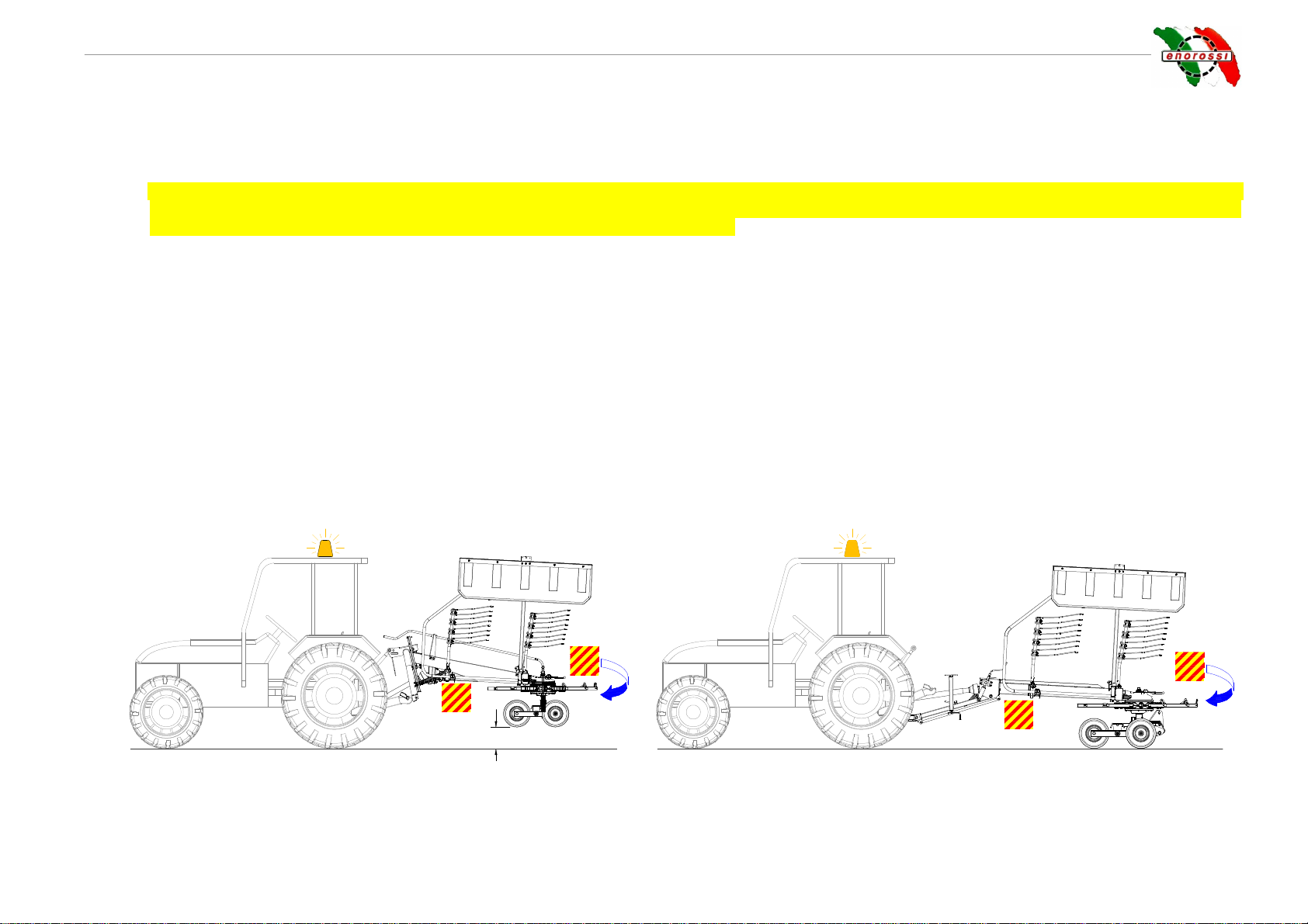
AFETY REGARDING TRANSPORT
,
INSTALLATION AND DISPLACEMENT
......................................................................10
B3
U
SE AND WARNINGS
.............................................................................................................................................13
B4
I
MPROPER USE AND USE LIMITS
.............................................................................................................................15
B5
R
ESPONSIBILITIES OF THE OPERATOR
....................................................................................................................15
B6
P
ICTOGRAMS
.......................................................................................................................................................16
B7
N
OISE
..................................................................................................................................................................17
INSTALLATION................................................................................................................................................................................................18
C1
P
RELIMINARY INFORMATION
..................................................................................................................................18
C2
I
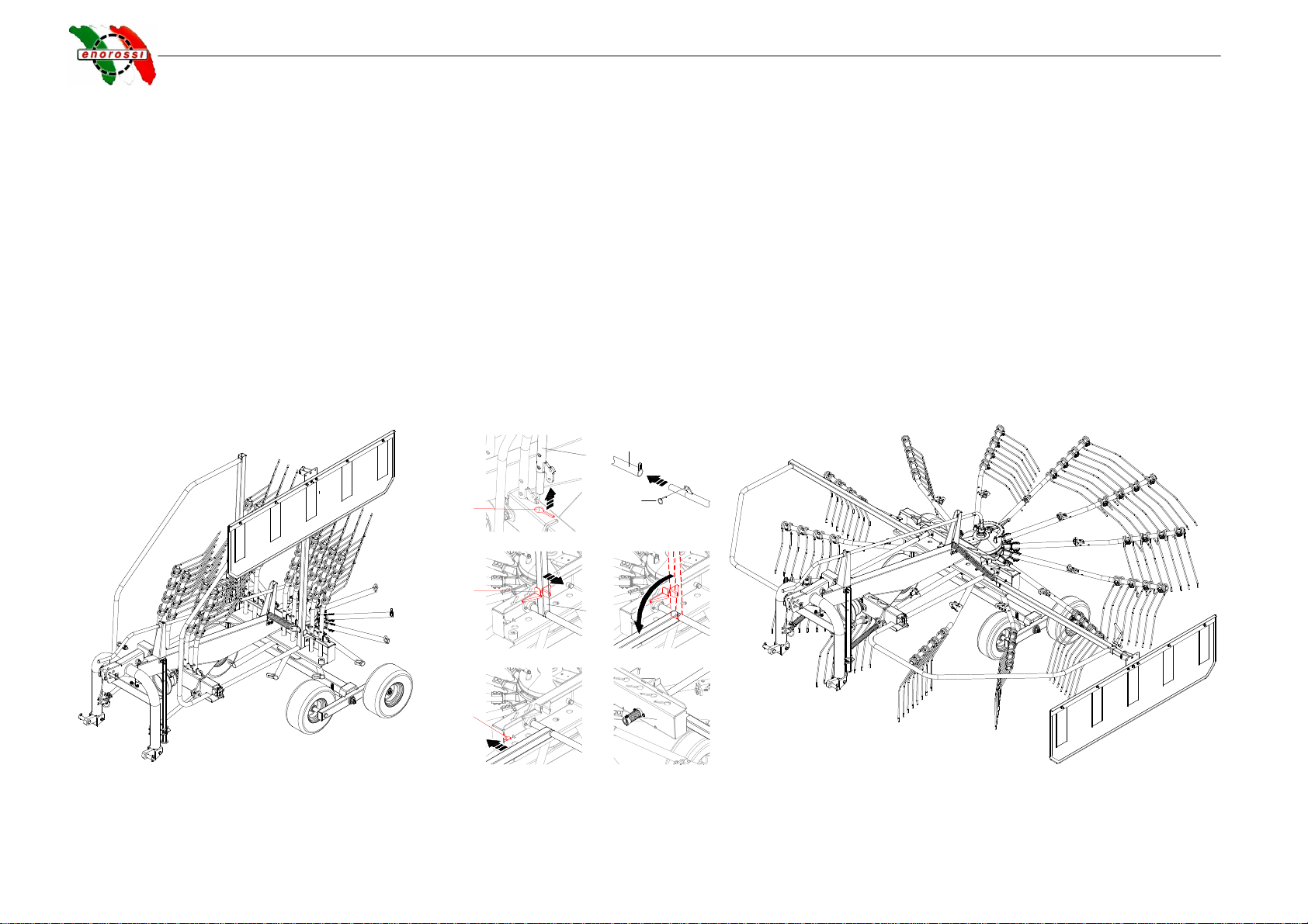
NSTALLATION TO TRACTOR
...................................................................................................................................18
C3
I
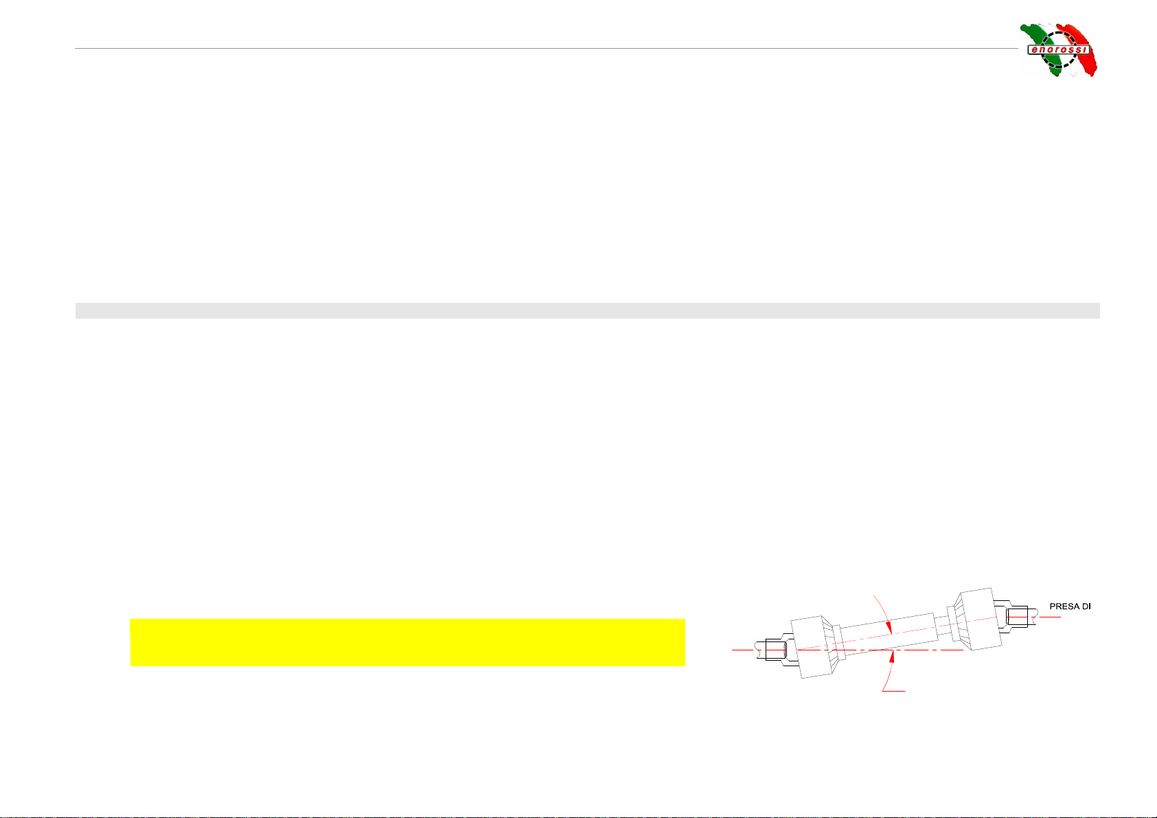
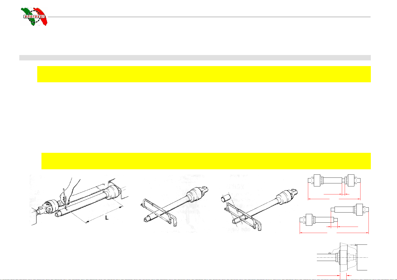
NSTALLATION AND ADJUSTMENT OF THE CARDAN SHAFT
.........................................................................................20
C4
H
YDRAULIC CONNECTIONS
....................................................................................................................................21
C5
R
EMOVAL
.............................................................................................................................................................21
C6
S
TORING THE WINDROW ROTARY RAKE
..................................................................................................................21
OPERATION AND USE....................................................................................................................................................................................22
D1
P
RELIMINARY INFORMATION
..................................................................................................................................22
D2
O
PERATION AND
U
SE
............................................................................................................................................22
D2.1
Work configuration....................................................................................................................................................................................................................22
D2.2
Work process............................................................................................................................................................................................................................23
D2.3
Quality of the windrow...............................................................................................................................................................................................................24
D2.4
Adaptation of the parallel windrow rotary rake to the ground...................................................................................................................................................24
D2.5
Adjustment of the windrow teeth distance from the ground......................................................................................................................................................25
Adjustment of the lift speed. ..............................................................................................................................................................................................................27
D2.6
Adjustment of the side deflector distance from the ground ......................................................................................................................................................28
D2.7
Adjustment of the side deflector excursion...............................................................................................................................................................................28
D2.8
Change of direction or in reverse..............................................................................................................................................................................................28

use and maintenance manual
4
D2.9
End of work...............................................................................................................................................................................................................................29
MAINTENANCE................................................................................................................................................................................................30
E1
W
ARNINGS DURING MAINTENANCE
.........................................................................................................................30
E2
M
AINTENANCE INTERVENTIONS
.............................................................................................................................30
E3
R
EPLACEMENT OF WINDROW TEETH
......................................................................................................................31
E4
T
ROUBLESHOOTER
...............................................................................................................................................32
E5
M
ATERIALS DISPOSAL IN CASE OF SCRAPPING
........................................................................................................32

use and maintenance manual
INTRODUCTION - 5
INTRODUCTION
A1 Information on the hay rakes
The windrow rotary rake is agricultural equipment used to collect any other type of previously cut forage, with formation of windrows. This equipment can work only
if installed on any agricultural tractor as long as provided with 3-point universal coupling and hydraulic lift. Fastened by a cardan shaft applied to the tractor PTO, its
operation is obtained by effect of its dragging by the machine towing it. The rotary motion of its work unit allows forming even and well ventilated windrows. Our
models, series “RR 400 e 450 EVO” (both mounted and pull type) are suitable for any kind of ground, either sloping or highly irregular.
More detailed information on the operation and use of the windrow rotary rake is described in the relative chapter.
A2 Information on the manual
ENOROSSI (hereinafter called “Manufacturer”) has designed and manufactured the equipment, in compliance with safety regulations, with the precise intention of
protecting personnel working near-by as well as the entire operational system.
Every windrow rotary rake is supplied with a copy of this manual that must be carefully read before its use. The manual contains information necessary for
transport, use and maintenance of the equipment, as well as the relative safety regulations.
The lacking in knowledge of the operational system may cause accidents, with consequent damages to the equipment. Therefore, even if upon delivery the
Manufacturer supplies the Customer all information relating to the windrow rotary rake (operation, use and maintenance); the Customer must read this manual and
observe the instructions therein.
The manual supplies the basic information for obtaining the best work and safety conditions but it remains the experience and good sense of the operator the most
important factor for the equipment functioning.
This manual was edited based on the current technical and constructive features of both windrow rotary rake models and does not take into account similar
products, previously manufactured. However, the Manufacturer reserves the right to make modifications to the models in production, in order to improve its product
or in case new relative dispositions are issued (Machinery Directive), without the obligation of adapting models previously manufactured.
This manual is an integrating part of the windrow rotary rake and, therefore, it must be well preserved, clean and intact in all its parts and stored in an appropriate
container, placed on the equipment frame or inside the tractor cabin, ready for consultation.
In case of transfer of the windrow rotary rake, verify the manual is present in its case. In case it is lost, request a duplicate from the Manufacturer.
If during reading of the manual the instructions should be incomprehensible, contact the Manufacturer for the opportune clarifications. Should the manual be
translated in other language and part of its content presents controversies, the valid text of reference remains that written in the Italian language.
Signals contained in the manual:
IMPORTANT

use and maintenance manual
6 - INTRODUCTION
To signal the information must be known by the operator;
To indicate a probably dangerous situation regarding the health of the operator and others (slight injuries or accidents) or the efficiency of the windrow
rotary rake;
The written Note indicates that the subject in question can facilitate the work carried out by the operator.
A3 Identification and EC certificates
Every equipment is provided with an identification plate applied on the frame and clearly visible, on which
the following data is reported:
-the model (and/or version) of the windrow rotary rake;
-serial number;
-minimum power of the tractor (kw);
-total weight (kg);
-year of manufacture.
This data must be quoted every time requesting assistance and spare parts.
IMPORTANT
It is strictly forbidden to alter and/or delete the data on the identification plate. However, the operator must
often verify legibility of the data and, when precarious, inform the Manufacturer. The manufacturer will
place the data on a new plate and replace the previous one.
The EC mark indicates the manufacturer has complied with the dispositions adopted by the Member states
of the European Community on health and safety, known as “Machinery Directive”. This means the manufacturer has designed and manufactured the equipment,
fully respecting all requisites for its use and avoiding all possible deriving risks and dangers. Therefore, the windrow rotary rake can freely circulate on the
European territory only if provided with this mark and relative declaration of conformity.
DANGER
ENOAGRICOLA ROSSI s.r.l.
GIROANDANATORE
ANNO Kg
MATRICOLA KwMODELLO
Tel. +39 075.9302222 - Fax +39 075.9302328
CALZOLARO DI UMBERTIDE - PERUGIA - ITALIA

use and maintenance manual
INTRODUCTION -
7
A4 Main components and technical data
1. Universal three point hitch
2. Cardan shaft coupling connection
3. Steering damper spring
4. Side protection screens
5. Work rotating unit
6. Teeth-holder arms
7. Side deflector
8. Wheels
9. Windrow teeth
10. Teeth-holder supports
11. Frame
12. Support foot
13. Teeth height adjustment lever
14. Towing connection
Technical features RR 400 EVO
PULL TYPE
RR 400 EVO
MOUNTED
RR 450 EVO
PULL TYPE
RR 400 EVO
MOUNTED
Working width with windrow m. .00 .00 .50 .50
Actual work m. 3.30 3.30 3.65 3.65
Windrow width m. 0.80 0.80 0.80 0.80
Transport width m. 1.70 1.70 1.70 1.70
Removable teeth-holder arms nr. 11 11 13 13
Arm double teeth / total nr. / .. / .. / .. / ..
PTO speed rpm 5 0 5 0 5 0 5 0
Tractor power kw/cv 22/30 22/30 22/30 22/30
Forward tractor speed km/h 15 15 15 15
Cardan shaft with torque limiter Nm 600 600 600 600
Tires mounted on wheels - Ballon 18”- 8.50”x 8” nr.
Standard tandem axle yes yes yes yes
Work height adjustment control Away From the tractor Away From the tractor
Windrow deposit left left left left
Equipment weight kg 625 600 6 0 61
12
11
10 9
87
6
4
5
34
2
1
13
12
13
14
TIPO TRAINATOTIPO PORTATO

use and maintenance manual
8 - INTRODUCTION
A5 Warranty
Enorossi (called Manufacturer) guarantees every component of the windrow rotary rake is without defects, as they are tested before delivering the machine to the
Customer. The warranty has a 1 year validity starting from the date indicated on the tax delivery document, except different agreements underwritten
with the Customer.
However, upon receipt of the windrow rotary rake, they must verify that it is intact and complete in its every part. Any claims must reach the Manufacturer in writing
within 8 days from receipt of the equipment.
Enorossi commits to replace the components that, for manufacturing or material defects, cause a fault in the operation at its establishment, within the warranty
period and free of charge. Should it not be possible such replacement at its own premises, the Manufacturer commits to sending the faulty pieces at the Customer's
premises. With regard to these replacements, Enorossi does not waiver the warranty period during the time which the windrow rotary rake remains still, or
recognises any damage or indemnity to the Customer, for direct and indirect expenses or damages. Should the intervention of our technician be required, the
relative labour, travel and overnight expenses will be fully charged to the Customer. Only the Manufacturer or its technicians can ascertain the fault.
However, it must be taken into consideration that:
the faulty pieces remain the property of the Manufacturer;
•should replacement be carried out at the Customer's establishment, the faulty pieces must be returned and, therefore, sent to the Manufacturer, for subjecting
to technical review, integrates without tampering, without tampering and carriage paid;
•in case faulty pieces cannot be returned to the Manufacturer within 30 days, from date of receiving the new ones and with the methods described in the
previous point, the Manufacturer reserves the right to sending an invoice for the new delivered pieces.
The warranty is not recognised:
•during transport as the windrow rotary rake travels under Customer responsibility;
•when faults derive from improper or incorrect use of the windrow rotary rake or operator negligence;
•when faults are caused by normal wear, even with the windrow rotary rake not working;
•in case of late signalling of the manufacturing defects;
•in case of accidents or fortuitous cases of force majeure.
The warranty becomes void in case:
•the windrow rotary rake is used by non- appropriately trained personnel;
•the indications and/or regulations in these instructions have not been followed or complied with;
•the envisioned maintenance interventions have not been carried out;
•the Customer makes modifications to the windrow rotary rake without the written authorisation of the Manufacturer or tampers with the components;

use and maintenance manual
INTRODUCTION -
9
•non-original spare parts are used or non-conform to those recommended by the Manufacturer.
However, the warranty period recognised for the windrow rotary rake is not valid for all components that are not produced by the Manufacturer and for which that
reported in the relative purchase notes remains valid.
IMPORTANT
The Manufacturer does not guarantee conformity of the windrow rotary rake with the legal dispositions in force and, in particular, with those relating to accident-
prevention and pollution in the non-E.U. countries. The adaptation of the windrow rotary rake to the respective regulations will be the full responsibility and at the
expense of the Customer. The Manufacturer is relieved from every responsibility, if the inobservance of these regulations raises controversies or causes any
damage.

use and maintenance manual
10 - SAFETY
SAFETY
B1 Main regulations
This manual describes safety regulations to observe in using the windrow rotary rake. As most of the accidents at work occur because the most basic safety
regulations are not complied with, it is compulsory, before activating any function, to read this manual and scrupulously follow the instructions herein.
The equipment must be used by adult personnel, qualified and trained on its use. Therefore, the Manufacturer does not answer for accidents caused by
operator negligence and/or non-compliance with the safety regulations. Also, both the Manufacturer's responsibility and the warranty of the windrow
rotary rake would immediately become void.
B2 Safety regarding transport, installation and displacement
•Transport (delivery): This operation is carried out by a vehicle with dimensions and weight suitable to the equipment. Load and unload operations from the
vehicle can be done either by using a lifting device or by using appropriate ramps hooked to the vehicle:
-
--
-
In the first case, the vehicle must have suitable features and slings to support the windrow rotary rake, which total weight is indicated in the
identification plate. Trained personnel will carry out the operation by holding the equipment in the indicated sections on the frame, set for this
purpose. - Note: to protect the integrity of the frame, it is recommended to not handle the windrow rotary rake with metal chains, but to use
approved belts. However, an adhesive label has been applied to the points where it should be fixed or sling should pass through, containing a
hook (as in figure), to highlight its use.
-
--
-
In the second case instead, by using a forklift truck or a tractor, the equipment is pushed in reverse to the vehicle loading surface.
In both cases, the equipment must be in compliance with the transport configuration (forward described) and, once placed on the vehicle, it must be fastened
to its structure and provided with all the safety devices required for transportation.
Load and unload operations always entail dangerous situations, thus requiring the operators in charge to be very
careful. However, it is recommended to always observe the following precautions:
-Operations must always be carried out on an even surface and by respecting a safe distance from escarpment or ditch borders;
-Ensure ramps are robust enough to support the windrow rotary rake, that are firmly fastened to the vehicle structure, parallel between them and
perpendicular to the vehicle side;
-Ensure ramps are clean, without any trace of oil, grease or ice;
-Do not change direction during ascent/descent operations of the windrow rotary rake on ramps. Should the path must be changed, take back the
equipment and proceed with its correction.
For long distances, the equipment is transported dismounted inside a wooden box. Once the items are delivered, detailed instructions allow the Customer to
easily and rapidly assemble the windrow rotary rake. So in the event the equipment is sold or transferred to another user, follow the instructions in the reverse
order to dismount it.
DANGER

use and maintenance manual
SAFETY -
11
•Installation: The pull type version windrow rotary rank can be installed on any agricultural tractor, provided with a towing connection and rear auxiliary
hydraulic jacks; whereas the mounted type version can be installed on any tractor provided with 3 point rear universal coupling and hydraulic lift.
IMPORTANT
The tractors must, in turn, be provided with protective roll-bar or ROPS or FOPS approved cabins, as indicated by the current Standards. It is strictly
forbidden to install the equipment on tractors without these protection devices. .
However, before installing, the Customer must consult the relative use and maintenance manual to ensure the tractor has the necessary requisites for the
windrow rotary rake use and function and/or is equipped with ballasts to eliminate any unbalances that might cause its overturn.
For instructions relating to the windrow rotary rake and any hydraulic connections, consult the relative paragraphs. For information relating to the cardan shaft,
follow those attached to the accessory.
•On-road displacement: Pull type windrow rotary rake can be displaced on road only if it is connected to the towing hook; whereas the mounted type must
be lifted by using the hydraulic lift, until the lowest section results at 30/40 cm from the ground and then block the hydraulic lift lever . In both cases, the
following obligations must be complied with:
-rear dimension: The operator must apply special panels to the windrow rotary rake (either if it is pulled or mounted type), to highlight the tractor rear
dimensions. In this regard, remember that the panels must be applied on the three visible sides and be retro-reflecting and fluorescent with yellow and red
stripes, and be approved. Moreover, transversal dimensions of the equipment must never be higher than the tractor's shape and therefore, it must always
assume the set transport configuration (with side protection screens closed and teeth-holder bar removed) as indicated in the figure.
MOUNTED TYPE VERSION PULL TYPE VERSION
-signs: Visual signal devices and tractor lighting devices must be repeated or moved if dimensions of the windrow rotary rake do not allow visibility.
Moreover, the tractor must be provided with the light flashing device (yellow or orange) always working;
30 - 40 cm

use and maintenance manual
12 - SAFETY
-weight: the total mass of the operational machine (tractor with windrow rotary rake) must not exceed 30% above the normal mass of the tractor, indicated
on its circulation paper; The tractor must always move at average speed, especially on disconnected roads, because the rear weight may cause difficulties
when driving;
-regulations: however, it is recommended to know and comply with road circulation regulations in force in each country.
During the operational machine on-road displacement (tractor+windrow rotary rake), the operator in the cabin must observe the following precautions:
-
must not take passengers on the tractor;
-
must not transport persons or animals on the equipment;
-
PTO must always be disconnected and with the lever blocked.
•In field displacement: To move within the cultivated fields, the operational machine (tractor with windrow rotary rake) must not activate any luminous signal or
buzzer or display any type of panel. The windrow rotary rake must assume the work configuration only before operating.
Windrow rotary rake (either mounted or pull type) in work configuration:
4
567
8
910
3
CONFIGURAZIONE DA TRASPORTO CONFIGURAZIONE DA LAVORO
1
2

use and maintenance manual
SAFETY -
13
-
--
-
One at a time, remove teeth-holder arms (2) from its supports on frame (1) and place them in their housings on work rotating unit (3) to then block them by
using safety pin (4);
-
--
-
first from a side and then from the other: Pull forward the side protection screen towards tractor connection (6), so to unhook it from the mechanical block
for transportation (5);
-
--
-
always keeping it pulled, rotate it downwards, as indicated in figure (7), and release it only when it is placed on the frame so to be blocked by its relative
work mechanical block (9). When screen (8) is released, appropriate spring (10) will take it back to the initial position. Note: on the left side of the windrow
rotary rake, the mechanical block is not set. The side deflector weight keeps the side screen position during the process;
-
--
-
for use and regulations of the process, refer to the subsequent paragraph.
B3 Use and warnings
The windrow rotary rake is agricultural equipment used to collect any other type of previously cut forage, with formation of windrows. The mounted type can work
only if installed on any agricultural tractor provided with 3-point universal coupling and hydraulic lift. The pull type, instead, must be connected to the towing hook
installed behind each tractor. The operation is common for both types and it is obtained either by effect of the tractor towing or by effect of the teeth-holder arm
rotation, which is responsible of the processing, guaranteed by a cardan shaft mounted on the tractor PTO. Both the arm rotating motion and the teeth action allow
to form even and well ventilated windrows.
On the pull type there are two jacks installed, which operation allows to adjust the teeth adaptation to the ground and to lift them for the tractor change of direction
at the end of the field or in reverse. These jacks are powered by the tractor auxiliary hydraulic circuit, through quick coupling pipes and controlled by a special lever
located inside the cabin.
The windrow rotary rake must be handled only by adult, qualified and trained personnel aware of the instructions contained in this manual. Safety is of primary
importance for the personnel working around the equipment or that carries out repair or maintenance operations. As the provided instructions cannot include all
work situations and their relative dangerousness, personnel must always be cautious and use common sense.
Warnings before use:
-Ensure the windrow rotary rake is mounted correctly on the tractor and if is equipped with all intact blocking and safety devices;
-Ensure the rpm is of 540 on the PTO and that it rotates clockwise. Moreover, ensure it is
disconnected and with its lever blocked;
IMPORTANT
PTO must never be inserted with the engine off and with an inclination higher than
10°between joints of the two connections (tractor/ windrow rotary rake);
-Ensure the cardan shaft is correctly installed and all blocking and safety devices are
present and intact. Should one of these be not installed or non-approved devices be mounted, the Manufacturer warns the Customer to not use such
shaft because it is forbidden;
PRESA DI
FORZA
TRATTORE
FORZA
ERPICE
10°max

use and maintenance manual
14 - SAFETY
-do not use the machine if failures or damages are present especially on
protective devices;
-only for the mounted type - lower slightly the equipment to the ground by
using the tractor hydraulic lift. Avoid violent impacts, which may provoke
damages to the structure or components;
-carry out daily maintenance operations(described in the relative paragraph). For
such purpose, remind that any kind of intervention (verification, adjustment,
maintenance, etc.) must be carried out with the equipment stopped, PTO
disconnected and the tractor engine off;
-Verify the position of the side deflector and teeth in relation to the ground.
Should their adjustment be required, consult the relative paragraphs;
-Ensure persons or animals do not stand in the equipment dangerous areas
(indicated in figure), as not aware of possible dangers;
-the operation of the equipment is allowed in good lighting and visibility
conditions. Should these conditions lack, even partially, it is recommended to
interrupt work as normal safe conditions would not be respected. Work should
only be restarted if the good visibility and lighting conditions are restored. Do
not use the equipment if failures or damages are present;
Warnings during use:
-always keep a forwarding speed of the tractor lower than 15 km/h when working;
-even for short stops, the operator must never abandon or leave the running tractor unattended. Before getting down the tractor, the operator must
always disconnect the PTO, block the hydraulic lift lever, engage the parking brake, switch off the engine of the tractor and remove the key from
the dashboard;
-During work-breaks, the operator must never allow non-authorised/qualified personnel to replace him;
-Before reversing with the tractor or for changes of direction at the end of the field, the operator must always ensure the windrow rotary rake is not in work
configuration and that its teeth are lifted at least 30 cm from the ground. For the mounted type, all the equipment must be lifted by using the tractor hydraulic
lift, whereas for the pull type the entire frame must be lifted, by hydraulic drive, controlled by one of the tractor circuit levers from the cabin (see also
paragraph D2.8 Change of direction or in reverse). The equipment may be seriously damaged if teeth are not lifted;
-the functioning of the windrow rotary rake does not produce noise so to use acoustic protection devices (plugs, headphones, etc.) but the tractor may produce
it. In this regard, consult the use and maintenance manual of the tractor;
-vibrations produced by the equipment that reach the operator are of low intensity and have a frequency that result lower than levels tolerated by human body.
However, it is important to keep transmission bodies and gears always lubricated. It is also important to often ensure screws are always tighten to
avoid excessive vibrations.
zona
pericolosa zona
pericolosa
zona pericolosa zona pericolosa

use and maintenance manual
SAFETY -
15
Stop immediately working if:
-it is close to resistant objects, such as drains, wells, shafts, etc., as the contact may break the teeth, which pieces can be projected around at a very high
speed;
-noisy vibrations that come from the equipment are felt. To avoid any damages, stop the tractor, disconnect the PTO, switch off the engine, and ,if feasible,
detect and remove the inconvenient by observing the safety regulations;
-on the pull type version oil leakage is detected. Do not seek the leakage with bare hands, but by using a cloth or protection gloves. Under pressure oil may
penetrate in the skin causing serious infections.
B4 Improper use and use limits
A different use of the windrow rotary rake from the one described in the previous paragraph is considered incorrect and so it is forbidden. Furthermore, its
technical features must not be altered to modify its performances, in any way. Should this happen, the equipment warranty and the Manufacturer
responsibility would immediately become void..
Visibility: in bad visibility conditions (fog, dust, smoke or other): It is recommended to stop unloading (stop the oven and unloader belt) and wait until fog, dust,
smoke or other softens. Behave the same way in case of wind and/or rain.
Dangerous areas: should a person or an animal enter in one of the dangerous areas, during the process (see previous paragraph), the operator must immediately
stop the operations (disconnect of the PTO and switch off the tractor) and send away the intruder. In the same way, when adjustment and/or maintenance
operations are carried out, non-authorised persons must neither stand nor move nearby the equipment.
Do not use the equipment if:
-the material to cut is humid or wet. in these conditions, it becomes sticky and it easily gather on the teeth affecting the function;
-its operation must take place nearby masonries. In these cases, besides the possibility to damage the teeth, a
dangerous projection of relative residuals may occur as well;
For any doubt relative to the use of the windrow rotary rake and not mentioned in this manual contact directly the Manufacturer.
B5 Responsibilities of the operator
Safety is of primary importance for the personnel working around the equipment and this is why each operator must be qualified, trained and adult who is directly
responsible for the operational control of the windrow rotary rake, its maintenance repairs and/or replacement of spare or consumption parts. This means the
operator cannot delegate to another operator, without his requisites, to replace him in his own functions. As the provided instructions cannot include all work
situations and their relative dangerousness, personnel must always be cautious and use common sense. So, everyone is responsible for damages caused to third
parties, himself, animals or objects if:
-he makes an incorrect or improper use of the equipment;
DANGER

use and maintenance manual
16 - SAFETY
-he uses the equipment under the effect of alcohol, medicines, drugs or if tired or sick;
-wear unsuitable cloths that may entangle in moving or rotating bodies;
-he is not aware of the instructions described in this manual;
-he does not observe road and safety regulations currently in force;
-not having previously verified the required requisites, coupling with the tractor cannot be performed (power or different features from the ones indicated in the
technical data table);
-he did not carry out the required maintenance operations, which, even if simple, they may cause damages to the equipment and create dangerous situations to
the people exposed, if they are not appropriate;
-he carried out modifications or non-authorised interventions to the equipment;
-he used non-original spare parts or non-conforming to the windrow rotary rake.
B6 Pictograms
In addition to the indications in this manual, to help operators, there are adhesive labels or pictograms applied in various parts of the equipment illustrating the
safety regulations to respect. Depending on the regulation, the labels vary in form and colour. Therefore, who work must know that the round signals indicate an
obligation (blue and white) or a prohibition (red, white and black), whereas the triangular ones indicate a danger (yellow and black). Other labels of rectangular
shape, as well as contain the danger or prohibition sign, supply further information on the safety regulation to respect. Regulations illustrated by the labels on the
windrow rotary rake are:
1. danger of hooking or entanglement. With rotating arms, their teeth may hook on to clothes or other objects worn by personnel in charge;
2. danger launch of objects. With the rotation of the arms, objects found on the place of use may be launched by the teeth; Safety minimum distance m.20;
3. prohibition to stand or transit. It is forbidden for persons not in charge to stand or move inside the operational area of the windrow rotary rake, when this is
running. Should it be necessary to move inside the operational area, stand at a safe distance (20 m) and be very cautious

use and maintenance manual
SAFETY -
17
4. obligation to read the use and maintenance
manual;
5. Ensure the rpm number set at the tractor
PTO output is of 540 rpm/min and that it
rotates clockwise.
IMPORTANT
The warning labels and pictograms must be
replaced before they become illegible. Should
one of them become illegible, the operator cannot
use the windrow rotary rake until a new label is
applied. It is also strictly forbidden to remove the
pictograms or labels from the equipment. Should
this happen, the Manufacturer declines every
responsibility this might entail, as the windrow
rotary rake would no longer have the safety
requisites with which it was designed and
manufactured.
B7 Noise
Not having its own motor, the noise produced by the equipment is due only to the mechanical movements of its parts therefore being neglectful compared to that
produced by the tractor dragging it. It is therefore not necessary for the operator to use acoustic protections (plugs, headphones, etc.). With regard to the noise
produced by the tractor, consult the relative use and maintenance manual.
M. 20
540
5
3
4
2
1

use and maintenance manual
18 - INSTALLATION
INSTALLATION
C1 Preliminary information
The pull type windrow rotary rake can be installed on any agricultural tractor provided with towing connection and rear auxiliary hydraulic jacks; whereas the
mounted type can be installed on any tractor provided with 3 point rear universal coupling and hydraulic lift. For the intervention this must be placed inside an area
with flat surface, arranged for the installation. The operator performing the intervention must be aware of the relative safety regulations and must work with the
utmost attention and caution.
C2 Installation to tractor
•Mounted type: The equipment is installed to the 3 point universal coupling of the hydraulic lift of the tractor. To do this, the operator must slowly approach the
tractor to the windrow rotary rake, positioning it so to facilitate its centring.
IMPORTANT
The alignment of the holes of the tractor coupling with those of the windrow rotary rake (operation defined centring), must be carefully and cautiously carried
out.
Once the manoeuvre is completed, the operator stops the tractor, leaves the lift in low position
blocking its activation lever, engages the parking brake, in case disconnects the controlled pull
and removes keys from the dashboard.
-he inserts lift arms (9) in the appropriate housings (low pins 1and 8) on the frame of
windrow rotary rake (6) and blocks them one by one by using safety pins (2);
-(should it not be present on the tractor) he places adjustable tie-rod (3) in the appropriate
housing of the tractor 3rd section (“heavy pull” hole) and he fastens it to the tractor by using
the provided pin;
-he loosens or tightens the tie-rod body of the windrow rotary rake, leaving volute (4) free ,
until it coincides with the housing on equipment frame (7);
-he fastens the tie-rod with pin (5), which he subsequently blocks with safety pin (6).
-Once carried out these operations, the operator climbs on the tractor and lifts the
equipment by activating the hydraulic lift lever and supported by another operator from the
ground, until the PTO has the same height of the tractor. Afterwards, he stops the tractor
again, blocks the hydraulic lift lever and adjusts the tie-rod (acting on his body), until the
frame of the windrow rotary rake is perfectly vertical, then he tightens the lock nut;
-finally, he blocks the arms of the hydraulic lift with the tie-rods or chains they are equipped
with.
6
2
8
9
1
7
54
3

use and maintenance manual
INSTALLATION -
19
1
2
3
4
6
9
5
7
8
FORO PER
CATENA
DI SICUREZZA
Once carried out the centring, the same operator lifts support foot (12) in a more suitable and safe position, both for the
transport phase and for the subsequent working phase. For this lifting, the operator removes pin (11) to release rue pin
(10) and then he removes the latter from the foot holes. He lifts the foot up to the lowest hole, as indicated in the figure
and he tightens it with the rue pin and relative pin.
Cardan shaft: For instructions relating to its installation and adjustment refer to its use and maintenance manual.
•Pull type: The equipment can be mounted on any agricultural tractor, by hooking it to the relative towing connection. To
do this, the operator must slowly approach the tractor to the windrow rotary rake, positioning it so to facilitate its centring
(1). IMPORTANT
The alignment of the holes of the tractor coupling with those of the windrow rotary rake (operation defined centring),
must be carefully and cautiously carried out.
When the tractor is close to the connection with the windrow rotary rake, an operator from the ground lifts or lowers the
windrow rotary rake connection by activating the support foot handle (2), so that it coincides with the tractor one. Once
carried out the connection, he places rue pin (3) in the relative connection holes, as indicated in the figure, and then he
fastens it by using its pin or safety pin(4).
Once carried out the centring, the same operator lifts the support foot from the ground, always by acting on handle (5), so
to complete the tractor connection operation. Then, he rotates support foot (8) in a more suitable and safe position, both
for the transport phase and for the subsequent working phase. For this rotation, the operator removes pin (6) to release
handle pin (7) and then he removes the latter from the foot holes. He rotates the foot of 180°, as indicated in fig ure (9) and he fastens it by placing the handle
pin and the relative pin.
12
11
10

use and maintenance manual
20 - INSTALLATION
Close to the towing connection, there is a hole where to connect the safety chain, which must be subsequently fastened to the tractor. The application of this
chain is not mandatory in Countries members of the European Union, however it is in other countries, as U.S.A.
C3 Installation and adjustment of the cardan shaft
•Installation: strictly observe instructions relative to installation indicated in its own use and maintenance manual.
IMPORTANT
Before installing the cardan shaft, ensure this has the requisites required for the type and power to transmit according to the rpm of the PTO. If required, verify
also the tractor use manual.
Should this not be used, is saying not installed on the PTO of the tractor but only on the windrow rotary rake one, lay the cardan shaft on the support located on
the mounted type or on the towing connection bar of the pull type.
•Adjustment: the cardan shaft (either provided with the equipment or sold as accessory) has a standard length. So it must be adjusted to the tractor where the
windrow rotary rake is installed. For this operation, proceed as follows:
-
--
-
remove protection devices from the cardan shaft;
-
--
-
remove the two parts that make up the shaft and join a part to the windrow rotary rake PTO, by clicking the spring safety pin and the other part to the tractor
PTO, by clicking the spring safety pin as well;
-
--
-
place the two parts of the cardan shaft beside and find the minimum sliding length (L). Should the shaft be too long, shorten the two external plastic
protection pipes, which must have the same size, and then the internal metallic ones. Smudge the cut parts and lubricate the internal parts.
IMPORTANT
When the cardan shaft is removed at its maximum, the two pipes must overlap for at least 15 cm. When it is inserted at its maximum, the minimum gap
allowed must be 4 cm.
-
--
-
remove the two parts of the cardan shaft from their connections (on the tractor and windrow rotary rake) and assemble the shaft,
by placing a part completely inside the other;
-
--
-
join again the two ends of the cardan shaft to the relative PTO by clicking the relative spring safety pins;
MAX
MIN
Min 4 cm
Min 15 cm
cm 5
This manual suits for next models
1
Table of contents
Other enorossi Farm Equipment manuals

enorossi
enorossi ENODUO TRACER 780 User manual

enorossi
enorossi ENOSPE US User manual

enorossi
enorossi MAXIMUS 12 User manual

enorossi
enorossi G2 Series User manual

enorossi
enorossi DM Series Operating instructions

enorossi
enorossi DR 420 4R User manual

enorossi
enorossi HAY TOP 300 User manual

enorossi
enorossi RR 350 EVO PROFI User manual

enorossi
enorossi G4V-3P User manual

enorossi
enorossi EASY RAKE Series Operating instructions