Bernecker + Rainer MAUSV1-E User manual

8QLQWHUUXSWLEOH3RZHU6XSSO\8369'&
81,17(55837,%/(
32 (56833/<
8369'&
8VHUV0DQXDO
Version: 1RYHPEHU
Mod. No.: 0$869(
We reserve the right to change the contents of this manual without warning. The information
contained herein is believed to be accurate as of the date of publication, however, Bernecker +
Rainer Industrie-Elektronik Ges.m.b.H. makes no warranty, expressed or implied, with regards
to the products or the documentation contained within this book. Bernecker + Rainer Industrie-
Elektronik Ges.m.b.H. shall not be liable in the event of incidental or consequential damages in
connection with or arising from the furnishing, performance or use of these products.
The software names, hardware names and trademarks used in this document are registered by
the respective companies.

8QLQWHUUXSWLEOH3RZHU6XSSO\8369'&

8QLQWHUUXSWLEOH3RZHU6XSSO\8369'&
&KDSWHU*HQHUDO,QIRUPDWLRQ
&KDSWHU%58369'&
&KDSWHU6RIWZDUH
&KDSWHU7HFKQLFDO$SSHQGL[

8QLQWHUUXSWLEOH3RZHU6XSSO\8369'&

8QLQWHUUXSWLEOH3RZHU6XSSO\8369'&
7DEOHRI&RQWHQWV
&KDSWHU*HQHUDO,QIRUPDWLRQ
1. Safety Guidelines .................................................................................................................. 9
1.1 Introduction ...................................................................................................................... 9
1.2 Intended Use ................................................................................................................... 9
1.3 Transport and Storage .................................................................................................. 10
1.4 Installation ..................................................................................................................... 10
1.5 Operation ....................................................................................................................... 10
1.5.1 Protection against Touching Electrical Parts .......................................................... 10
2. Safety Notices ..................................................................................................................... 11
3. Manual History .................................................................................................................... 11
&KDSWHU%58369'&
1. Model Numbers .................................................................................................................. 14
2. Technical Data .................................................................................................................... 15
2.1 USV 24 VDC 9A0100.11 ............................................................................................... 15
2.2 Battery Units and Accessories ...................................................................................... 16
3. Figures / Dimensions .......................................................................................................... 18
3.1 UPS 24 VDC ................................................................................................................ 18
3.2 UPS Battery Unit Type A (24V 7.2 Ah) ........................................................................ 19
3.3 UPS Battery Unit Type B (24V 2.2 Ah) ........................................................................ 21
3.4 UPS Battery Unit Type C (24V 4.5 Ah) ......................................................................... 23
3.5 Mounting the UPS Device ............................................................................................ 25
4. Overview of Components ................................................................................................... 26
4.1 Component Descriptions ............................................................................................... 26
4.1.1 Power Mains Connection ........................................................................................ 26
4.1.2 Load Connection ..................................................................................................... 27
4.1.3 Fuses ...................................................................................................................... 27
4.1.4 Battery Connection ................................................................................................. 28
4.1.5 Relay Output ........................................................................................................... 28
4.1.6 External Button, Temperature Sensor Connection ................................................. 29
4.1.7 RS232 Interface ...................................................................................................... 29
4.1.8 User Button ............................................................................................................. 30
4.1.9 Status LEDs ............................................................................................................ 31
5. UPS Installation .................................................................................................................. 32
&KDSWHU6RIWZDUH
1. Configuring the UPS using the B&R UPS Configuration Software ..................................... 33
1.1 Installation of the B&R UPS Configuration Software ..................................................... 33
1.2 Starting the B&R UPS Configuration Software .............................................................. 34
1.3 Uninstalling the B&R UPS Configuration Software ....................................................... 36
1.4 B&R UPS Configuration Software Structure ................................................................. 37
1.5 Description of the Individual Tabs: ................................................................................ 39
1.5.1 "About" Tab ............................................................................................................. 39
1.5.2 "Settings" Tab ......................................................................................................... 40
1.5.3 "Firmware" Tab ....................................................................................................... 41

8QLQWHUUXSWLEOH3RZHU6XSSO\8369'&
7DEOHRI&RQWHQWV
1.5.4 "Communication" Tab ............................................................................................. 43
1.5.5 "Service" Tab .......................................................................................................... 44
1.6 Monitoring the Load System using the B&R UPS Configuration Software .................... 45
1.6.1 Monitoring on Windows 95/98/ME/NT4.0/2000/XP ................................................. 45
1.7 Security Configuration / Menu Language ...................................................................... 49
1.7.1 Menu Functions ...................................................................................................... 50
2. Monitoring using Windows NT4.0 with Operating System UPS Service ............................ 51
3. Monitoring using Windows 2000 with Operating System UPS Service .............................. 52
4. Monitoring using Windows XP with Operating System UPS Service ................................. 55
5. Configuring the UPS using HyperTerminal ......................................................................... 58
5.1 Setting TWL (Time Worst Low) ..................................................................................... 58
5.2 Setting SDT (Shut Down Time) ..................................................................................... 59
5.3 Setting POT (Power On Time) ..................................................................................... 59
5.4 Setting LCS (Load Current Set) ................................................................................... 60
5.5 Setting PFL (Power Fail Level) ...................................................................................... 61
5.6 Setting CTL (Charge Temperature Low) ....................................................................... 62
5.7 Setting CTH (Charge Temperature High) ...................................................................... 62
5.8 Setting AGE (Battery Lifespan) ..................................................................................... 63
5.9 Checking and Reading the UPS Parameters ................................................................ 64
&KDSWHU7HFKQLFDO$SSHQGL[
1. UPS Functions .................................................................................................................... 65
2. UPS Behavior ..................................................................................................................... 66
2.1 Buffer Operation ............................................................................................................ 67
2.2 Secure Shut Down ........................................................................................................ 67
2.3 Switching on the UPS .................................................................................................... 67
2.4 UPS Overload Behavior ................................................................................................ 70
2.5 User Button and External Button (Digital Input) ............................................................ 70
2.5.1 Additional Function of the User Button starting with UPS Firmware V2.0 .............. 70
2.6 Serial Interface .............................................................................................................. 71
2.6.1 Power Failure .......................................................................................................... 72
2.6.2 Operation without the RS232 cable ........................................................................ 75
2.7 Relay Output ................................................................................................................. 76
2.7.1 Contact Data ........................................................................................................... 76
2.8 Rechargeable Batteries ................................................................................................. 77
2.8.1 Characteristics of Lead Acid Battery 12 VDC 7.2 Ah .............................................. 77
2.8.2 Characteristics of Lead Acid Battery 12 V, 2.2 Ah .................................................. 78
2.8.3 Characteristics of Hawker Cyclon Rechargeable Battery 12 V, 4.5 Ah .................. 78
2.8.4 Mounting Instructions for Rechargeable Batteries .................................................. 79
2.8.5 Parallel Connection of Batteries .............................................................................. 80
2.8.6 Setting the Maximum Charging Current .................................................................. 81
2.8.7 Charging and Discharging Characteristics of the Lead Acid Battery ...................... 82
2.8.8 Lead Acid Battery Lifespan ..................................................................................... 83
2.8.9 LC-R122R2P Data Sheet ........................................................................................ 84
2.8.10 LC-P127R2P Data Sheet ...................................................................................... 85
3. UPS Command Sequences ................................................................................................ 86

8QLQWHUUXSWLEOH3RZHU6XSSO\8369'&
7DEOHRI&RQWHQWV
3.1 Detecting the UPS Operating Mode .............................................................................. 86
3.2 Requesting UPS Standard Parameters ......................................................................... 87
3.2.1 UPS Firmware < 2.0 ................................................................................................ 87
3.2.2 UPS Firmware >= 2.0 ............................................................................................. 87
3.3 Writing UPS Parameters ............................................................................................... 87
3.3.1 TWL (Time Worst Low) ........................................................................................... 87
3.3.2 SDT (Shut Down Time) ........................................................................................... 88
3.3.3 POT (Power On Time) ............................................................................................ 88
3.3.4 LCS (Load Current Set) .......................................................................................... 88
3.3.5 PFL (Power Fail Level) ........................................................................................... 89
3.3.6 CTL (Charge Temperature Low) ............................................................................. 89
3.3.7 CTH (Charge Temperature High) ........................................................................... 89
3.3.8 AGE (lifespan of rechargeable battery) ................................................................... 90
3.3.9 BCR (Battery Change Request) .............................................................................. 90
3.3.10 Read the UPS time stamp (WHRD) ...................................................................... 91
3.4 Battery Operation Parameters ....................................................................................... 92
3.4.1 Panasonic LC-R127R2P 7.2 Ah (9A0100.12) ......................................................... 92
3.4.2 Panasonic LC-R122R2P 2.2 Ah (9A0100.14) ......................................................... 92
3.4.3 Hawker Cyclon 4.5 Ah (9A0100.16) ........................................................................ 92
4. Glossary .............................................................................................................................. 93

8QLQWHUUXSWLEOH3RZHU6XSSO\8369'&
7DEOHRI&RQWHQWV

8QLQWHUUXSWLEOH3RZHU6XSSO\8369'&
Chapter 1
General Information
*HQHUDO,QIRUPDWLRQ6DIHW\*XLGHOLQHV
&KDSWHU*HQHUDO,QIRUPDWLRQ
6DIHW\*XLGHOLQHV
,QWURGXFWLRQ
Programmable logic controllers (e.g. PLCs, etc.), operating and monitoring devices (e.g.
Industrial PCs, Power Panels, Mobile Panels, etc.) as well as the B&R uninterruptible power
supplies have been designed, developed or manufactured for conventional use in industry. They
were not designed, developed and manufactured for any use involving serious risks or hazards
that without the implementation of exceptionally stringent safety precautions could lead to death,
injury, serious physical damage or loss of any other kind. Such risks and hazards include in
particular the use of these devices in the monitoring of nuclear reactions in nuclear power plants
and of flight control systems, in flight safety, in the control of mass transportation systems, in
medical life support systems, and in the control of weapons systems.
Both when using programmable logic controllers and when using operating and monitoring
devices as control systems in conjunction with a Soft PLC (e.g. B&R Automation Runtime or
comparable products) or a Slot PLC (e.g. B&R LS251 or comparable products), the safety
precautions applying to industrial control systems (e.g. the provision of safety devices such as
emergency stop circuits, etc.) in accordance with applicable national and international
regulations must be observed.
All tasks such as installation, commissioning and service may only be carried out by qualified
personnel. Qualified personnel are persons who are familiar with the transport, mounting,
installation, commissioning and operation of the product and have the appropriate qualifications
(e.g. IEC 60364). National accident prevention guidelines must be followed.
The safety guidelines, connection descriptions (rating plate and documentation) and limit values
listed in the technical data must be read carefully before installation and commissioning and
must be observed.
,QWHQGHG8VH
Electronic devices are generally not fail-safe. In the event of a failure on the programmable
control system, operating or monitoring device or uninterruptible power supply, the user is
responsible for ensuring that other devices that may be connected, such as motors, are made
safe.

8QLQWHUUXSWLEOH3RZHU6XSSO\8369'&
*HQHUDO,QIRUPDWLRQ6DIHW\*XLGHOLQHV
7UDQVSRUWDQG6WRUDJH
During transport and storage, the devices must be protected from excessive stress (mechanical
load, temperature, humidity, aggressive atmosphere).
,QVWDOODWLRQ
• The installation must take place according to the documentation using suitable
equipment.
• The devices may only be installed when isolated from the power supply and by
qualified personnel.
• General safety regulations and nationally applicable accident prevention guidelines
must be observed.
• Electrical installation must be carried out according to the relevant guidelines (e.g.
line cross section, fuse, protective ground connection).
2SHUDWLRQ
3URWHFWLRQDJDLQVW7RXFKLQJ(OHFWULFDO3DUWV
To operate programmable logic controllers, operating and monitoring devices and uninterruptible
power supplies, certain components must carry dangerous voltage levels of over 42 VDC. A life-
threatening electrical shock could occur if you touch these parts. This could result in death,
severe injury or material damage.
Before turning on the programmable logic controller, the operational and monitoring devices and
the uninterruptible power supply, ensure that the housing is properly connected to protective
ground (PE rail). The ground connection must be established even when testing the operating
and monitoring devices and the uninterruptible power supply as well as when operating them for
only a short time.
Before turning the device on, make sure that all voltage carrying parts are securely covered.
During operation, all covers must remain closed.

8QLQWHUUXSWLEOH3RZHU6XSSO\8369'&
Chapter 1
General Information
*HQHUDO,QIRUPDWLRQ6DIHW\1RWLFHV
6DIHW\1RWLFHV
Safety notices are organized as follows:
All dimension diagrams (e.g. dimension diagrams, etc.) are drawn
according to European dimension standards.
0DQXDO+LVWRU\
Safety Notice Description
Disregarding the safety regulations and guidelines can result in death or severe damage to the product.
Disregarding the safety regulations and guidelines can result in severe injury or heavy damage to material
or the product.
Disregarding the safety regulations and guidelines can result in injury or damage to material and the product.
Table 1: Safety notices
Version Date Comments
4.8 23.09.2002 Changes / New Features
- Error in Figure 7 "Dimensions of UPS battery unit type B (24V 2.2 Ah)" - Dimensions for the distance
between mounting holes corrected
- Maximum cable length (15m) for self made RS232 connection cables added
- 9A0100.16 UPS battery unit type C 24 V 4.5 Ah added
- 9A0100.17 UPS batteries 2 pcs. 12 V 4.5 Ah added
- Safety guidelines added
- Description of new commands starting with UPS firmware version 2.0
- B&R UPS configuration software functions added starting with version 2.0
- Section “Monitoring using Windows XP with Operating System UPS Service" on page 55 added
- “UPS Command Sequences" on page 86 added
- “UPS Overload Behavior" on page 70 added
- Description of new UPS configuration software functions
- Switching thresholds added
Table 2: Manual history

8QLQWHUUXSWLEOH3RZHU6XSSO\8369'&
*HQHUDO,QIRUPDWLRQ0DQXDO+LVWRU\
4.7 03.10.2001 Changes / New Features
- New manual structure
- B&R UPS configuration software added
- Mistake regarding the possible storage/operating position for the lead gel rechargeable battery
corrected
- New layout
4.6 19.04.2001 Changes / New Features
- Mistake in the cable description corrected
- Mistake regarding the hand shake signal line corrected
4.5 29.09.2000 Changes / New Features
4.4 07.09.2000 Changes / New Features
- New layout
4.3 18.08.2000 First Edition
Version Date Comments
Table 2: Manual history (cont.)
8QLQWHUUXSWLEOH3RZHU6XSSO\8369'&
Chapter 2
B&R UPS 24 VDC
%58369'&
14
&KDSWHU%58369'&
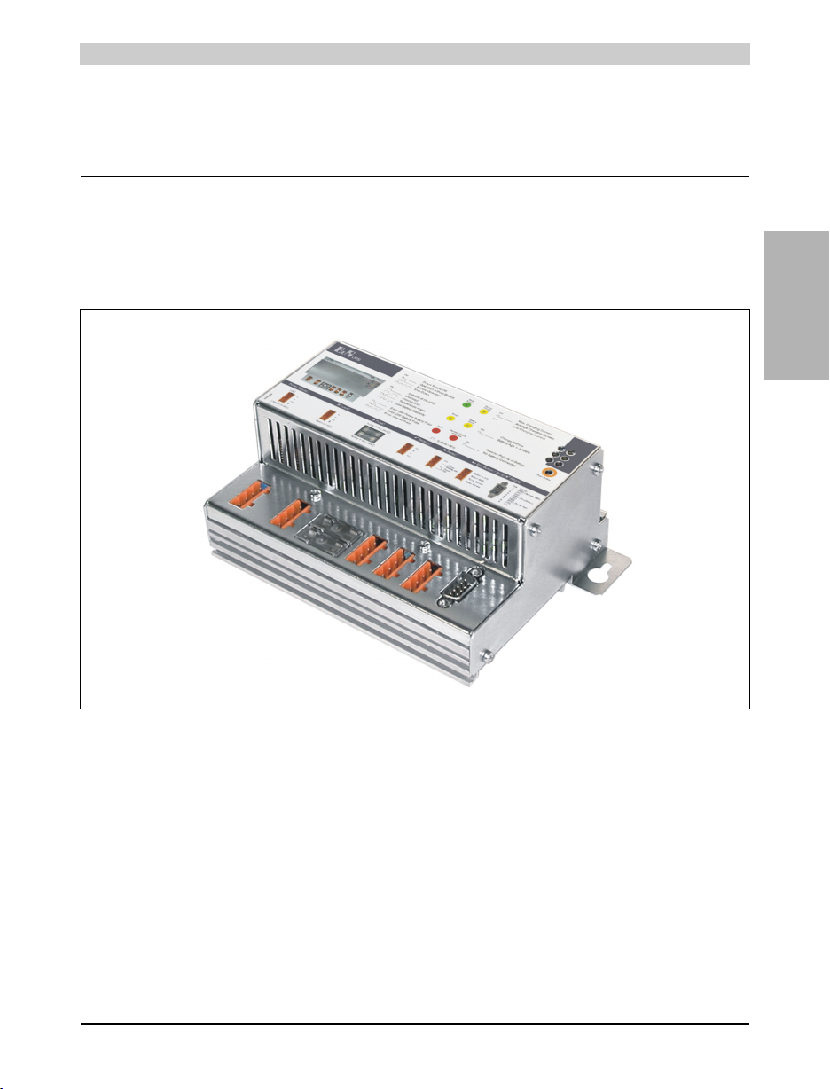
The UPS is used to supply power for systems which cannot be connected directly to the 24 V
power mains for safety reasons because a power failure could cause data to be lost. The UPS
allows the load (e.g. IPCs) to be shut down securely without losing data if a power failure occurs.
Features:
• 24 VDC input voltage
• 24 VDC output voltage
• Industrial standard installation
• Communication via serial interface
• Status display
• Deep discharge protection
• Short circuit protection
• Maintenance free rechargeable batteries
Figure 1: UPS device 9A0100.11

8QLQWHUUXSWLEOH3RZHU6XSSO\8369'&
%58369'&0RGHO1XPEHUV
0RGHO1XPEHUV
Model Number Description Remark
9A0017.01 RS232 Null Modem Cable 0.6 m
To connect UPS and IPC (9 pin DSUB socket - 9 pin DSUB socket)
9A0017.02 RS232 Null Modem Cable 1.8 m
To connect UPS and IPC (9 pin DSUB socket - 9 pin DSUB socket)
9A0100.11 UPS 24 VDC
24 VDC input, 24 VDC input, serial interface
9A0100.12 UPS Battery Unit Type A
24 V; 7 Ah; including battery cage
9A0100.13 UPS Battery Unit Type A
2 x 12 V; 7 Ah; for battery unit 9A0100.12 replacement part
9A0100.14 UPS Battery Unit Type B
24 V; 2.2 Ah; including battery cage
9A0100.15 UPS Battery Unit Type B
2 x 12 V; 2.2 Ah; for battery unit 9A0100.14 replacement part
9A0100.16 UPS Battery Unit, Type C 24V 4.5Ah
24 V; 4.5 Ah; including battery cage
9A0100.17 UPS Battery Unit, Type C 24V 4.5Ah
2 x 12 V; 4.5 Ah; for battery unit 9A0100.16 replacement part
MAUSV1-0 UPS User Documentation, German
MAUSV1-E UPS User Documentation, English
MAUSV1-F UPS User Documentation, French
Table 3: Model numbers

8QLQWHUUXSWLEOH3RZHU6XSSO\8369'&
Chapter 2
B&R UPS 24 VDC
%58369'&7HFKQLFDO'DWD
7HFKQLFDO'DWD
8699'&$
Product ID UPS 24 VDC
Model Number 9A0100.11
Input during Mains Operation
Rated voltage value
Voltage range
Regulated DC voltage
24 VDC
20 - 30 VDC at a switching threshold of 18 V 1)
23.5 - 30 VDC at a switching threshold of 21.5 V 1)
Output during Mains Operation
Rated voltage value
Voltage range
Max. output current
24 VDC
20 - 30 VDC or 23.5 - 30 VDC according to the set switching threshold 1)
8 A
Output during Battery Operation
Switching threshold mains/battery
operation 1)
Rated voltage value
Voltage range
Max. output current
Mains failure bridging
1) Can be set using B&R configuration software or HyperTerminal (18 or 21.5 VDC)
18 V at 20 - 30 VDC input
21.5 V at 23.5 - 30 VDC input
24 VDC
21 - 26.8 VDC (40° C) or 28.2 VDC (0° C)
8 A (load)
max. 20 minutes with 150 W load (with battery 9A0100.12, 24 V / 7.2 Ah)
Battery Charging Rating
Charging clearing voltage
Charging current
27.6 VDC
From 0.88 A to 2.88 A depending on type
adjustable in 0.01 A increments: using B&R UPS configuration software and
HyperTerminal (0.5 - 2.88 A)
or 0.25 A: using button (0.88 to 2.88 A)
Protection and Monitoring
Deep discharge protection
Short circuit protection
Fuses
Reverse polarity protection
Yes; depending on the set switching threshold: 21 V when 18 V 1) or 21.5 V when 21.5 V 1)
Yes
Yes; for mains supply, battery and battery charger
Yes; for mains supply and battery
Status Display
Operating mode
Status
Battery charging current
Battery status
Battery reverse polarity
Fuses
LED green (mains operation, battery operation, etc.)
LED yellow (overload, temperature alarm, etc.)
LED yellow (charging current strength)
LED yellow (battery change, age, etc.)
LED red (battery reverse polarity, not connected)
LED red (mains supply, battery, battery charger)
Interface
CTS (Clear To Send)
DCD (Data Carrier Detect)
DTR (Data Terminal Ready)
Serial, RS232
Signals power failure
Signals shutdown
Signals remote shutdown of the UPS
Software Support Microsoft Windows 95 / 98 / ME / NT4.0 / 2000 / XP
Standards UL
Environmental Temperature 0 - 55 °C
Relative Humidity 5 - 95 %, (non-condensing)
Dimensions (W x H x D) 185 x 115 x 69 mm
Weight Approx. 1.1 kg
Table 4: Technical data UPS 24VDC 9A0100.11

8QLQWHUUXSWLEOH3RZHU6XSSO\8369'&
%58369'&7HFKQLFDO'DWD
%DWWHU\8QLWVDQG$FFHVVRULHV
Product ID UPS Battery Unit Type A (24V 7.2 Ah)
Model Number 9A0100.12
Batteries UPS batteries; 2 pcs., 12V; 7.2 Ah (9A0100.13)
Connection Cable
For charger
For temperature sensor
Length 3 m; cross section 2.5 mm²
Length 3 m; cross section 0.75 mm²
Dimensions (W x H x D) 200 x 155 x 125 mm
Weight Approx. 6.1 kg
Product ID UPS batteries; 2 pcs., 12V; 7.2 Ah
Model Number 9A0100.13
Type Panasonic 12V 7.2 Ah; two rechargeable batteries connected in series
Sort Maintenance free lead acid battery
Installation Mounting methods see "The Lead Acid Battery" on page 79
Environmental Temperature 0 - 40 °C
Lifespan 1.5 - 10 years
(dependent on environmental temperature and the charging and discharging cycles)
Product ID UPS Battery Unit Type B (24V 2.2 Ah)
Model Number 9A0100.14
Batteries UPS batteries; 2 pcs., 12V; 2.2 Ah (9A0100.15)
Connection Cable
For charger
For temperature sensor
Length 3 m; cross section 2.5 mm²
Length 3 m; cross section 0.75 mm²
Dimensions (W x H x D) 180 x 120 x 80 mm
Weight Approx. 2.3 kg
Product ID UPS batteries; 2 pcs., 12V; 2.2 Ah
Model Number 9A0100.15
Type Panasonic 12V 2.2 Ah; two rechargeable batteries connected in series
Sort Maintenance free lead acid battery
Installation Mounting methods see "The Lead Acid Battery" on page 79
Environmental Temperature 0 - 40 °C
Lifespan 1.5 - 10 years
(dependent on environmental temperature and the charging and discharging cycles)
Table 5: Technical data for battery units and accessories
8QLQWHUUXSWLEOH3RZHU6XSSO\8369'&
Chapter 2
B&R UPS 24 VDC
%58369'&7HFKQLFDO'DWD
Product ID UPS Battery Unit Type C (24V 4.5 Ah)
Model Number 9A0100.16
Batteries UPS batteries; 2 pcs., 12V; 4.5 Ah (9A0100.17)
Dimensions (W x H x D) 223.2 x 145 x 78.2 mm
Weight Approx. 5 kg
Product ID UPS batteries; 2 pcs., 12V; 4.5 Ah
Model Number 9A0100.17
Type Hawker Cyclon 12V 4.5 Ah; two rechargeable batteries connected in series
Sort Single cell
Installation Mounting methods see "Hawker Cyclon Rechargeable Batteries" on page 79
Charging Environment Temperature -40 °C to +80 °C
Storage Temperature -65 °C to +80 °C
Lifespan 10 -15 years
(dependent on environmental temperature and the charging and discharging cycles)
Product ID RS232 DB9 null modem cable 0.6 m
Model Number 9A0017.01
Pin Assignment See Table 12 "Pin assignment RS232 cable"
Product ID RS232 DB9 null modem cable 1.8 m
Model Number 9A0017.02
Pin Assignment See Table 12 "Pin assignment RS232 cable"
Table 5: Technical data for battery units and accessories (cont.)

8QLQWHUUXSWLEOH3RZHU6XSSO\8369'&
%58369'&)LJXUHV'LPHQVLRQV
)LJXUHV'LPHQVLRQV
8369'&
Product ID UPS 24 VDC
Model Number 9A0100.11
Table 6: Order data for UPS 24 VDC
Figure 2: UPS on mounting rail
Figure 3: Dimensions of UPS 24 VDC

8QLQWHUUXSWLEOH3RZHU6XSSO\8369'&
Chapter 2
B&R UPS 24 VDC
%58369'&)LJXUHV'LPHQVLRQV
836%DWWHU\8QLW7\SH$9$K
Product ID UPS Battery Unit Type A (24V 7.2 Ah)
Model Number 9A0100.12
Table 7: Order data for UPS battery unit type A (24V / 7.2 Ah)
Figure 4: UPS battery unit type A (24V 7.2 Ah)

8QLQWHUUXSWLEOH3RZHU6XSSO\8369'&
%58369'&)LJXUHV'LPHQVLRQV
Figure 5: Dimensions of UPS battery unit type A (24V 7.2 Ah)
Table of contents
Popular Power Supply manuals by other brands


Rohde & Schwarz
Rohde & Schwarz R&S NGP800 Series user manual

Epson
Epson SCI 7660 SERIES user guide

BEL
BEL LEC480 Series installation instructions

Velleman-Kit
Velleman-Kit K2570 Illustrated assembly manual

Zeta Alarm Systems
Zeta Alarm Systems SSG1 instruction manual

Bticino
Bticino 375005 quick start guide