manuals.online logo
Brands
  1. Home
  2. •
  3. Brands
  4. •
  5. IFM Electronic
  6. •
  7. Power Supply
  8. •
  9. IFM Electronic E84016 User manual

IFM Electronic E84016 User manual

1 EN Instruction Manual DC Power Supply
E84016
E84036
2 DE Bedienungsanleitung DC Stromversorgung
3 FR Manual d'instructions DC Alimentation d'Énergie
4 ES Manual de instrucciones DC Fuente De Alimentación
5 IT Manuale di Istruzione DC Gruppo di alimentazione
6 PT Manual de Instruções DC Fonte De Alimentação
Read this first! English 1
Before operating this unit please read this manual thoroughly and retain this manual for future reference! This device may only be installed and put into operation by qualified personnel. If damage or
malfunction should occur during operation, immediately turn power off and send unit to the factory for inspection. The unit does not contain serviceable parts. The tripping of an internal fuse is caused
by an internal defect. The information presented in this document is believed to be accurate and reliable and may change without notice. For any clarifications the English translation will be used.
Intended Use: This power supply is designed for installation in an enclosure and is intended for general use such as in industrial control, office, communication, and instrumentation equipment. Do
not use this device in equipment, where malfunction may cause severe personal injury or threaten human life.
WARNING CAUTION
Risk of electrical shock, fire, personal injury or death.
1) Do not use the power supply without proper grounding (Protective Earth).
2) Turn power off before working on the device. Protect against inadvertent re-powering.
3) Make sure that the wiring is correct by following all local and national codes.
4) Do not modify or repair the unit.
5) Do not open the unit as high voltages are present inside.
6) Use caution to prevent any foreign objects from entering the housing.
7) Do not use in wet locations or in areas where moisture or condensation can be expected.
8) Do not touch during power-on, and immediately after power-off. Hot surfaces may cause burns.
Reduction of output current may be necessary when:
1) Minimum installation clearance can not be met.
2) Altitude is higher than 2000m.
3) Device is used above +60°C ambient.
4) Mounting orientation is other than input terminal located at the bottom of the unit.
5) Airflow for convection cooling is obstructed.
Vor Inbetriebnahme lesen! Deutsch 2
Bitte lesen Sie diese Warnungen und Hinweise sorgfältig durch, bevor Sie das Gerät in Betrieb nehmen. Bewahren Sie die Anleitung zum Nachlesen auf. Das Gerät darf nur durch fachkundiges und
qualifiziertes Personal installiert werden. Bei Funktionsstörungen oder Beschädigungen schalten Sie sofort die Versorgungsspannung ab und senden das Gerät zur Überprüfung ins Werk. Das Gerät
beinhaltet keine Servicebauteile. Interne Sicherungen lösen nur bei Gerätedefekt aus. Die angegebenen Daten dienen allein der Produktbeschreibung und sind nicht als zugesicherte Eigenschaften
im Rechtssinne aufzufassen. Im Zweifelsfall gilt der englische Text.
Bestimmungsgemäßer Gebrauch: Diese Stromversorgung ist für den Einbau in ein Gehäuse konzipiert und zur Verwendung für allgemeine elektronische Geräte, wie z.B. Industriesteuerungen,
Bürogeräte, Kommunikationsgeräte oder Messgeräte geeignet. Benutzen Sie dieses Gerät nicht in Steuerungsanlagen, in denen eine Funktionsstörung zu schweren Verletzungen führen oder
Lebensgefahr bedeuten kann.
WARNUNG VORSICHT
Missachtung nachfolgender Punkte kann einen elektrischen Schlag, Brände, schwere Unfälle oder Tod
zur Folge haben.
1) Betreiben Sie die Stromversorgung nie ohne Schutzleiter.
2) Schalten Sie die Eingangsspannung vor Installations-, Wartungs- oder Änderungsarbeiten ab und
sichern Sie diese gegen unbeabsichtigtes Wiedereinschalten.
3) Sorgen Sie für eine ordnungsgemäße und fachgerechte Verdrahtung.
4) Führen Sie keine Änderungen oder Reparaturversuche am Gerät durch.
5) Gerät niemals öffnen. Im Inneren befinden sich gefährliche Spannungen.
6) Verhindern Sie das Eindringen von Fremdkörpern, wie z.B. Büroklammern und Metallteilen.
7) Betreiben Sie das Gerät nicht in feuchter Umgebung oder in einer Umgebung, bei der mit Betauung
oder Kondensation zu rechnen ist.
8) Gehäuse nicht während des Betriebes oder kurz nach dem Abschalten berühren. Heiße
Oberflächen können Verletzungen verursachen.
Rücknahme der Ausgangsleistung kann erforderlich sein:
1) wenn die minimalen Einbauabstände nicht eingehalten werden können.
2) bei Aufstellhöhen über 2000m.
3) Betrieb bei Umgebungstemperaturen über +60°C.
4) bei Einbaulagen abweichend von der Standardeinbaulage (Eingangsklemmen an der
Unterseite des Geräts).
5) bei behinderter Luftzirkulation.
A lire avant mise sous tension! Français 3
Merci de lire ces instructions de montage et d'entretien avant de mettre l'alimentation sous tension. Conservez ce manuel qui vous sera toujours utile. Cette alimentation doit être installée par du
personnel qualifié et compétent. Le déclenchement du fusible interne traduit très probablement un défaut au niveau de l'appareil. Si un défaut quelconque apparaît en cours de fonctionnement,
débrancher au plus vite l'alimentation. Dans ce deux cas de figure, il convient de faire contrôler l'alimentation en usine! Les données indiquées dans ce document servent uniquement à donner une
description du produit et n'ont aucune valeur juridique. En cas de divergences, le texte anglais fait foi.
Utilisation: Cet appareil est conçu pour être installé dans une armoire et pour tous les équipements électroniques, tel que l'équipement industriel de commande, l'équipement de bureau, le matériel
de communication et les instruments de mesures. N'utilisez pas cet appareil sur des installations dans lesquels un problème de fonctionnement de l'alimentation pourrait causer des blessures graves
ou menacer la vie humaine.
AVERTISSEMENT ATTENTION
Prendre en compte les points suivants, afin d'éviter toute détérioration électrique, incendie, dommage
aux personnes ou mort.
1) ne jamais faire fonctionner l'alimentation sans raccordement à la terre !
2) débrancher l'installation avant toute intervention sur l'alimentation (ou démontage) et s'assurer qu'il
n'y a pas risque de redémarrage.
3) s'assurer que le câblage a été fait selon les prescriptions
4) ne pas effectuer de réparations ou modifications sur l'alimentation
5) ne pas ouvrir l'appareil. Des tensions importantes passent à l'intérieur.
6) veiller à ce qu'aucun objet ne rentre en contact avec l'intérieur de l'alimentation (trombones, pièces
métalliques)
7) ne pas faire fonctionner l'appareil dans un environnement humide ou à l'extérieur, non protégé. Ne
pas utiliser l'appareil dans un environnement où il peut y avoir de la condensation.
8) ne pas toucher le carter pendant le fonctionnement ou après la mise sous tension. Surface chaude
risquant d’entraîner des blessures.
Des limitations de puissance de sortie peuvent apparaître si :
1) les distances d'installation mini. ne peuvent être observées
2) installation à une altitude > 2000 m
3) pour des fonctionnements en charge et avec une température ambiante > 60°C
4) pour des positions de montage différentes de la préconisation standard (entrée dessous)
5) lorsque la circulation d'air est gênée
ifm electronic
Lea primero! Español 4
Conserve este manual como referencia para futuras consultas. La fuente de alimentación solo puede ser instalada y puesta en funcionamiento por personal cualificado. Por favor lea detenidamente
este manual antes de conectar la fuente de alimentación. Cuando se funde un fusible interno, existe gran probabilidad de un fallo interno en el equipo.Si se produce un fallo o mal funcionamiento
durante la operación, desconecte inmediatamente la tensión de alimentación. En ambos casos, el equipo debe ser inspeccionado en fábrica. La información presentada en este documento es
exacta y fiable en cuanto a la descripción del producto y puede cambiar sin aviso. En casa de duda, prevalece el texto inglés.
Uso apropiado: Este equipo ha sido diseñado para su instalación en un ambiente cerrado y ha sido concebido para uso general en instalaciones de control industrial, oficinas, comunicaciones y
equipos de instrumentación. No emplee esta unidad en equipos, donde un mal funcionamiento puede ocasionar lesiones graves o riesgo mortal.
ADVERTENCIA ATENCIÓN
Riesgo de descarga eléctrica, incendio, accidente grave o muerte.
1) No conectar nunca la unidad sin conexión de puesta a tierra.
2) Desconectar la tensión de red antes de trabajar en la fuente de alimentación. Evite una posible
reconexión involuntaria.
3) Asegurarse de que el cableado es correcto de acuerdo a los códigos locales y nacionales.
4) No realizar ninguna modificación o reparación de la unidad.
5) No abrir nunca la unidad. En el interior existe riesgo de altas tensiones.
6) Evitar la introducción en la carcasa de objetos extraños.
7) No usar el equipo en ambientes húmedos. No operar el equipo en ambientes donde se espere la
formación de rocío o condensación.
8) No tocar durante el funcionamiento ni inmediatamente después del apagado. El calor de la
superficie puede causar quemaduras graves
La deriva en la corriente de salida es applicable:
1) cuando no pueden mantenerse las distancias mínimas de montaje.
2) en caso de que el montaje se realice en altitudes superiores a los 2000 m.
3) en caso de funcionamiento a plena carga y temperaturas ambientales superiores a
+60ºC.
4) En caso de que la posición de montaje sea diferente a la posición estándar (Terminales
de entrada abajo).
5) en caso de que la circulación de aire para la refrigeración por conducción esté
obstruida.
Leggere prima questa parte! Italiano 5
Prima di collegare il sistema di alimentazione elettrica si prega di leggere attentamente le seguenti avvertenze. Conservare le istruzioni per la consultazione futura. Il sistema di alimentazione elettrica
deve essere installato solo da personale competente e qualificato. In caso di intervento del fusibile interno, molto probabilmente l'apparecchio è guasto. Se durante il funzionamento si verificano
anomalie o guasti, scollegare immediatamente la tensione di alimentazione. In entrambi i casi è necessario far controllare l'apparecchio dal produttore! I dati sono indicati solo a scopo descrittivo del
prodotto e non vanno considerati come caratteristiche garantite dell'apparecchio.In caso di differenze o problemi è valido il testo inglese
Uso previsto: Questo apparecchio è previsto per il montaggio in un rack per moduli elettronici, ad esempio per controllori industriali, apparecchiature per ufficio, unità di comunicazione o apparecchi
di misura. Non utilizzare questo apparecchio in apparati o impianti dove il malfunzionamento può causare danni alla persona o pericolo di vita.
AVVERTENZA ATTENZIONE
Il mancato rispetto delle seguenti norme può provocare folgorazione elettrica, incendi, gravi incidenti e
perfino la morte.
1) Non far funzionare in nessun caso il sistema di alimentazione elettrica senza conduttore di
protezione!
2) Prima di eseguire interventi di installazione, di manutenzione o di modifica scollegare la tensione di
rete ed adottare tutti i provvedimenti necessari per impedirne il ricollegamento non intenzionale.
3) Assicurare un cablaggio regolare e corretto.
4) Non tentare di modificare o di riparare da soli l'apparecchio.
5) Non aprire l'apparecchio. Al suo interno sono applicate tensioni elettriche pericolose.
6) Impedire la penetrazione di corpi estranei nell'apparecchio, ad esempio fermagli o altri oggetti
metallici.
7) Non far funzionare l'apparecchio in un ambiente umido. Non far funzionare l'apparecchio in un
ambiente soggetto alla formazione di condensa o di rugiada.
8) Non toccare quando acceso e subito dopo lo spegnimento. La superficie calda può causare
scottature.
È necessario ridurre la potenza di uscita se:
1) non è possibile rispettare le distanze minime di montaggio;
2) l'apparecchio viene installato in un luogo di altitudine maggiore di 2000 m;
3) il funzionamento è a pieno carico a temperatura ambiente maggiore di +60°C;
4) Morsetti d’ingresso posti in basso al modulo.
5) è ostacolata la libera circolazione dell'aria.
Leia primeiro! Portuguès 6
Recomendamos a leitura cuidadosa das seguintes advertências e observações, antes de colocar em funcionamento a fonte de alimentação. Guarde as Instruções para futura consulta, em casos de
dúvida. A fonte de alimentação deverá ser instalada apenas por profissionais da área, tecnicamente qualificados. Se o fusível interno se fundir, é grande a possibilidade de existir um defeito no
aparelho. Se por acaso, durante a utilização ocorrer algum defeito de funcionamento ou dano, desligue imediatamente a tensão de alimentação. Em ambos os casos, será necessária uma
verificação na Fábrica! Os dados mencionados têm como finalidade somente a descrição do produto, e não devem ser interpretados como propriedades garantidas no sentido jurídico. Em caso de
duvidas aplica-se o texto em inglês.
Utilize: Este aparelho foi concebido para ser montado dentro de invólucros, caixas ou armários para aparelhos eletrônicos em geral, como, por exemplo, comandos de instalações industriais,
aparelhos para escritórios, aparelhos de comunicação ou instrumentos de medida e quadros eléctricos. Não utilize este aparelho em instalações, nos quais um defeito de funcionamento poderá
causar danos graves ou significar risco de morte.
ATENÇÃO CUIDADO
A não observância ou o incumprimento dos pontos a seguir mencionados, poderá causar uma
descarga elétrica, incêndios, acidentes graves ou morte.
1) Não use a fonte de alimentação sem o condutor de proteção terra!
2) Antes de trabalhos de instalação, manutenção ou modificação, desligue a tensão de alimentação,
protegendo-a contra uma nova ligação involuntária.
3) As ligações devem ser efectuadas apenas por profissionais competentes.
4) Não efectue nenhuma modificação ou tentativa de reparação no aparelho. Quando necessário
contacte o seu distribuidor.
5) Não abra o aparelho mesmo quando desligado. No seu interior existem condensadores que podem
estar carregados electricamente.
6) Proteger a fonte de alimentação contra a introdução inadvertida de corpos metálicos, como por ex.,
clipes ou outras peças de metal.
7) Não usar o aparelho em ambientes húmidos. Não usar o aparelho em ambientes propensos a
condensações.
8) Não tocar enquanto estiver em funcionamento, nem após a desligar. A superficie poderá estar
quente e provocar lesões.
Será necessário reduzir a potência de saída nos seguintes casos:
1) Quando não forem observadas as distâncias mínimas de montagem.
2) Quando instaladas a altitudes superiores a 2000m.
3) Existencia de temperatura ambiente superior a +60ºC, em plena carga do aparelho.
4) Quando a posição de montagem é diferente da posição normal (para baixo terminais de
entrada).
5) Montagem em ambiente sem ventilação.
ifm electronic gmbh
Friedrichstraße 1
45128 Essen
Germany
Power Supply Instruction Manual
Bedienungsanleitung für Stromversorgung
ifm electronic
Technical Data Technische Daten E84016 1) E84036 2)
Output Voltage Ausgangsspannung nom. DC 24-28V DC 24-28V
Factory Setting at Full Load Werkseinstellung bei Nennlast typ. 24.1V 24.1V
Output Current continuous Ausgangsstrom dauernd nom. 40A at 24V, 34.4A at 28V 40A at 24V, 34.4A at 28V
Output Current short-term Ausgangsstrom kurzzeitig nom. 60A at 24V, 51.5A at 28V 60A at 24V, 51.5A at 28V
Output Power continuous Ausgangsleistung dauernd nom. 960W 960W
Output Power short-term Ausgangsleistung kurzzeitig nom. 1440W 1440W
Output Ripple & Noise Voltage 7) Ausgangswelligkeit
7) max. 100mVpp 100mVpp
Output Overload Behavior Überlastverhalten am Ausgang - Advanced Hiccup 13) continuous current
Input Voltage 10) Eingangsspannung
10) nom. AC 100-240V -15%/+10% 3AC 380-480V -15%/+20%
Input Frequency Eingangsfrequenz nom. 50-60Hz ±6% 50-60Hz ±6%
Input Current Eingangsstrom typ. 8.6A / 4.5A 3) 1.65A / 1.35A / Phase 4)
Power Factor Leistungsfaktor typ. 0.99 / 0.99 3) 0.88 / 0.9 4)
PFC Norm EN 61000-3-2 PFC Norm EN 61000-3-2 Class A Yes / Ja Yes / Ja
Input Inrush Current Einschaltspitzenstrom typ. 17A / 11A peak3) 5) 4.5A / 4.5A peak4) 5)
Hold-up Time Pufferzeit typ. 27ms / 27ms 3) 25ms / 25ms 4)
Efficiency Wirkungsgrad typ. 93.6% / 94.6% 3) 95.3% / 95.2% 4)
Power Losses Verlustleistung typ. 65.6W / 54.8W 3) 47.3W / 48.4W 4)
Operational Temperature Range Betriebstemperaturbereich nom. -25°C - +70°C -25°C - +70°C
Output Derating Leistungsrücknahme +60°C to +70°C 24W/°C 24W/°C
Storage Temperature Range Lagertemperaturbereich nom. -40°C - +85°C -40°C - +85°C
Humidity 12)Feuchte
12) IEC 60068-2-30 5 – 95% r.H. 5 - 95% r.H.
Vibration Schwingen IEC 60068-2-6 1g 1g
Shock Schocken IEC 60068-2-27 15g 6ms, 10g 11ms 15g 6ms, 10g 11ms
Degree of Pollution Verschmutzungsgrad IEC 62103 2 12)212)
Degree of Protection Schutzart EN 60529 IP20 IP20
Class of Protection Schutzklasse IEC 61140 I 6) I 6)
Over-temperature Protection Übertemperaturschutz OTP Yes / Ja Yes / Ja
Output Over-voltage Protection Überspannungsschutz am Ausgang OVP, max. 32Vdc 32Vdc
Return Voltage Resistance 8) Rückspeisefestigkeit
8) max. 35Vdc 35Vdc
Parallel Use Parallelschaltbar - Yes / Ja 11) Yes / Ja 11)
DC-OK Signal Contact DC-OK Signalkontakt Yes / Ja 14) Yes / Ja 14)
Dimensions 9) (WxHxD) Abmessungen
9) (BxHxT) nom. 125x124x127mm 110x124x127mm
Weight Gewicht max. 1900g, 4.2lb 1500g, 3.3lb
1) All parameters are specified at 230Vac input voltage, nominal output current, 25°C ambient
and after a 5 minutes run-in time unless otherwise noted.
2) All parameters are specified at 3x400Vac input voltage, symmetrical phase voltages, nominal
output current, 25°C ambient and after a 5 minutes run-in time unless otherwise noted.
3) At 120Vac, 60Hz / 230Vac, 50Hz
4) At 400Vac, 50Hz / 480Vac, 60Hz
5) Inrush current actively limited and temperature independent.
6) PE connection required (Ground).
7) 50-Ohm measurement, bandwidth 20MHz
8) Loads such as decelerating motors and inductors can feed voltage back to the output of the
power supply. The figure represents the maximum allowed feed back voltage
9) Depth without DIN-rail.
10)Below 90Vac, an output current derating is necessary.
11)Set unit into “Parallel Mode”
12)Do not energize while condensation is present.
13)At heavy overloads or short circuit across the output, the power supply delivers continuous
output current for 2s. After this, the output is switched off for approx. 18s before a new start
attempt is automatically performed. This cycle is repeated as long as the overload exists.
14)The relay contact is closed when the terminal voltage is higher than 90% of the adjusted
output value. Contact ratings: 60Vdc 0.3A; 30Vdc 1A; 30Vac, 0.5A, see figure 6.
1) Alle Werte gelten bei 230Vac Eingangsspannung, Nennausgangsstrom, 25°C Umgebung und
nach einer Aufwärmzeit von 5 Minuten, falls nichts anderes angegeben.
2) Alle Werte gelten bei 3x400Vac Eingangsspannung, symmetrischer Phasenspannungen,
Nennausgangsstrom, 25°C Umgebung und nach einer Aufwärmzeit von 5 Minuten, falls
nichts anderes angegeben.
3) Bei 120Vac, 60Hz / 230Vac, 50Hz
4) Bei 400Vac, 50Hz / 480Vac, 60Hz
5) Aktiv begrenzter Einschaltstrom, temperaturunabhängig.
6) PE Verbindung erforderlich.
7) 50-Ohm Messung, Bandbreite 20MHz
8) Bremsende Motoren oder Induktivitäten können Spannung zum Ausgang des Netzteils
rückspeisen. Der Wert gibt die max. zulässige Rückspeisespannung an.
9) Tiefe ohne DIN-Schiene
10)Unterhalb 90Vac ist eine Leistungsrücknahme erforderlich.
11)Gerät in „Parallel Modus“ schalten
12)Nicht betreiben, solange das Gerät Kondensation aufweist.
13)Bei Überlast oder Kurzschluss am Ausgang liefert die Stromversorgung für 2 Sekunden
kontinuierlichen Strom und schaltet danach ab. Alle 18s erfolgen erneute Startversuche
solange die Überlast besteht.
14)Der Relaiskontakt ist geschlossen sobald die Ausgangsspannung größer als 90% des
eingestellten Wertes ist. Kontaktspezifikation: 60Vdc 0,3A; 30Vdc 1A; 30Vac, 0,5A (Bild 6).
Installation
Use DIN-rails according to EN 60715 with a height of 7.5 or 15mm. Mounting orientation must be
input terminals on the bottom. Do not obstruct air flow as the unit is convection cooled. Ventilation
grid must be kept free of any obstructions. The following installation clearances must be kept
when power supplies are permanently fully loaded:
Left / right: 5mm (15mm in case the adjacent device is a heat source)
40mm on top, 20mm on the bottom of the unit.
Installation
Geeignet für DIN-Schienen entsprechend EN 60715 mit einer Höhe von 7,5 oder 15mm. Der
Einbau hat so zu erfolgen, dass sich die Eingangsklemmen unten befinden. Luftzirkulation nicht
behindern! Das Gerät ist für Konvektionskühlung ausgelegt. Es ist für ungehinderte Luftzirkulation
zu sorgen. Folgende Einbauabstände sind bei dauerhafter Volllast einzuhalten:
Links / rechts: 5mm (15mm bei benachbarten Wärmequellen)
Oben: 40mm, unten 20mm vom Gerät.
CE Marking
CE mark is in conformance with EMC directive and the low-voltage directive (LVD).
EMC Immunity: EN 61000-6-1, EN 61000-6-2
EMC Emission: EN 61000-6-3, EN 61000-6-4, FCC Part 15 Class B
CE Kennzeichnung
Das CE Zeichen ist angebracht und erklärt die Erfüllung der EMV Richtlinie und der
Niederspannungsrichtlinie.
Störfestigkeit: EN 61000-6-1, EN 61000-6-2
Störaussendung: EN 61000-6-3, EN 61000-6-4, FCC Part 15 Klasse B
Fig. 1 / Bild 1 E84016 Functional Diagram / Funktionsschaltbild Fig. 2 / Bild 2 E84036 Functional Diagram / Funktionsschaltbild
+
+
-
-
V
OUT
DC-ok
Contact
Output
Over-
Voltage
Protection
Bridgeless
PFC
Converter
Input Fuse
Input Filter
Inrush Limiter
Output
Voltage
Regulator
Power
Converter Output
Filter
DC ok
Relay
Output
Voltage
Monitor
Output
Power
Manager
Temper-
ature
Shut-
down
Overload
LED
DC-ok
LED
N
L
Single /
Parallel
Shut-down
Input &
Remote
Control
Shut-
down
13
14
15
16
Event Datalogger
+
+
-
-
V
OUT
DC-ok
Contact
Output
Over-
Voltage
Protection
PFC
Converter
Input Fuses
Input Filter
Input Rectifier
Inrush Limiter
Transient Filter
Output
Voltage
Regulator
Power
Converter Output
Filter
DC ok
Relay
Output
Voltage
Monitor
Output
Power
Manager
Temper-
ature
Shut-
down
Overload
LED
DC-ok
LED
L2
L3
L1
Single /
Parallel
Shut-
down
13
14
15
16
Shut-down
Input &
Remote
Control
Power Supply Instruction Manual
Bedienungsanleitung für Stromversorgung
ifm electronic
External Input Protection
The power supplies have an internal input fuse included which is not user accessible. An external
protection is only required if the supplying branch has an ampacity greater than 32A. Check also
local codes and requirements. If an external fuse is necessary or utilized, minimum requirements
need to be considered to avoid nuisance tripping of the circuit breaker.
E84016: Use a minimum value of 16A B- or C-Characteristic breaker.
E84036: Use a minimum value of 6A B- or C-Characteristic breaker.
Externe Eingangsabsicherung
Das Gerät besitzt eine eingebaute Eingangssicherung, die nicht anwenderzugänglich ist. Ein
externes Schutzelement ist nur bei einem Anschluss an ein Stromnetz größer 32A oder wenn
nationale Richtlinien es vorschreiben, erforderlich. Um ein fehlerhaftes Auslösen externer
Schutzelemente zu vermeiden sollen die angegebenen Minimalwerte nicht unterschritten werden.
E84016: Bei externem Schutz den Wert von 16A B- oder C-Charakteristik nicht unterschreiten.
E84036: Bei externem Schutz den Wert von 6A B- oder C-Charakteristik nicht unterschreiten.
Terminals and Wiring
Use appropriate copper cables that are designed for a minimum operating temperature of:
60°C for ambient temperatures up to 45°C,
75°C for ambient temperatures up to 60°C and
90°C for ambient temperatures up to 70°C.
Follow national installation codes and regulations! Ensure that all strands of a stranded wire enter
the terminal connection! Ferrules are allowed.
Input Output Signals
Solid wire 0.5-6mm2 0.5-16mm2 0.15-1.5mm2
Stranded wire 0.5-4mm2 0.5-10mm2 0.15-1.5mm2
American wire gauge AWG 20-10 AWG 22-8 AWG 26-14
Max. wire diameter 2.8mm 5.2mm 1.5mm
(including ferrules)
Wire stripping length 7mm / 0.28inch 12mm / 0.5inch 7mm / 0.28inch
Tightening torque 1Nm / 9lb.inch 2.3Nm / 20.5lb.inch Spring-clamp terminal
Anschlussklemmen und Verdrahtung
Verwenden Sie geeignete Kupferkabel, die mindestens für:
60°C bei einer Umgebungstemperatur bis zu 45°C,
75°C bei einer Umgebungstemperatur bis zu 60°C und
90°C bei einer Umgebungstemperatur bis zu 70°C zugelassen sind.
Beachten Sie nationale Bestimmungen und Installationsvorschriften! Stellen Sie sicher, dass
keine einzelnen Drähte von Litzen abstehen. Aderendhülsen sind erlaubt.
Eingang Ausgang Signale
Starrdraht 0,5-6mm2 0,5-16mm2 0,15-1,5mm2
Litze 0,5-4mm2 0,5-10mm2 0,15-1,5mm2
AWG AWG 20-10 AWG 22-8 AWG 26-14
Max. Drahtdurchmesser 2,8mm 5,2mm 1,5mm
(inklusive Aderendhülsen)
Abisolierlänge 7mm / 0,28inch 12mm / 0,5inch 7mm / 0,28inch
Anzugsdrehmoment 1Nm / 9lb.inch 2.3Nm / 20,5lb.inch Federkraftklemme
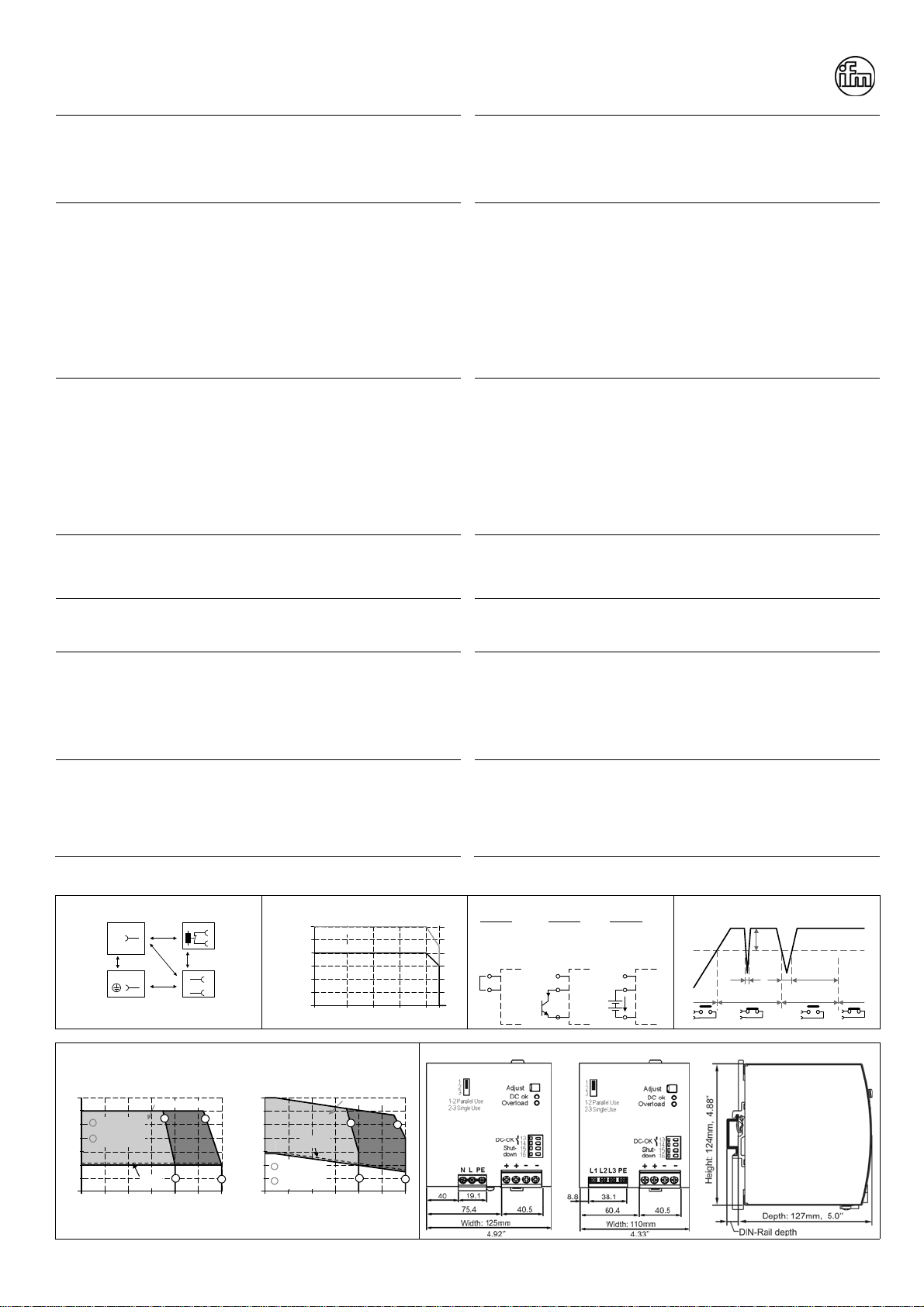
Isolation and Dielectric Strength (see Fig. 3)
The output voltage is floating and separated from the input according to SELV (IEC/EN 60950-1)
and PELV (EN 60204-1, EN 50178; IEC 62103, IEC 60364-4-41) requirements. Type and factory
tests are conducted by the manufacturer. Field tests may be conducted in the field using the
appropriate test equipment which applies the voltage with a slow ramp (2s up and 2s down).
Connect all phase-terminals together as well as all output poles before the test is conducted.
When testing, set the cut-off current settings to the value in the table below.
A B C D
Type Test (60s) 2500Vac 3000Vac 500Vac 500Vac
Factory Test (5s) 2500Vac 2500Vac 500Vac 500Vac
Field Test (5s) 2000Vac 2000Vac 500Vac 500Vac
Cut-off current setting >20mA >20mA >40mA >1mA
Galvanische Trennung und Isolationsfestigkeit (siehe Bild 3)
Die Ausgangsspannung hat keinen Bezug zur Erde oder Schutzleiter und ist zum Eingang nach
den SELV (IEC/EN 60950-1) und PELV (EN 60204-1, EN 50178, IEC 62103, IEC 60364-4-41)
Standards getrennt. Typ- und Stückprüfungen werden beim Hersteller durchgeführt.Wieder-
holungsprüfungen dürfen mittels geeigneten Prüfgenerators mit langsam (2s) ansteigenden und
abfallenden Spannungsrampen in der Anwendung erfolgen. Vor den Tests sind alle Phasen wie
auch alle Ausgangspole miteinander zu verbinden. Während der Tests darf die Strom-
A
bschaltschwelle nicht kleiner als der in der Liste angegebene Wert sein.
A B C D
Typprüfung (60s) 2500Vac 3000Vac 500Vac 500Vac
Stückprüfung (5s) 2500Vac 2500Vac 500Vac 500Vac
Wiederholungsprüfung (5s) 2000Vac 2000Vac 500Vac 500Vac
Strom- Abschaltschwelle >20mA >20mA >40mA >1mA
Shut-down Input (see Fig. 5)
This feature allows a switch-off of the power supply with a control switch or an external voltage.
The shut-down function has no safety feature included. The shut-down occurs immediately while
the turn-on is delayed by 350ms. In a shut-down condition, the output voltage is <2V and the
output power is <0.5W.
„Shut-down“ Eingang (siehe Bild 5)
A
bschaltung des Gerätes durch einen Signalschalter oder eine Fremdspannung. Die Abschaltung
beinhaltet keine Sicherheitsfunktionen. Die Abschaltung erfolgt unverzögert, das
Wiedereinschalten mit einer Verzögerung von ca. 350ms. Im abgeschaltetem Zustand ist die
A
usgangsspannung <2V und die Ausgangsleistung <0,5W.
Output and Overload Characteristic (see Fig. 7)
The units are overload, no-load, short-circuit proof and are designed to support loads with a
continuous power demand of up to 960W and a short-term power demand of up to 1440W without
damage or shut-down.
Ausgangs- und Überlastverhalten (siehe Bild 7)
Die Geräte sind leerlauf-, überlast- und kurzschlussfest und sind zur Versorgung von Lasten mit
einem Dauerleistungsbedarf bis zu 960W und einem kurzzeitigem Leistungsbedarf bis 1440W
konstruiert ohne dabei Schaden zu nehmen.
Single Use / Parallel Use Selector (see Fig. 7)
This selector on the front of the unit enables a load sharing when power supplies are connected in
parallel. The “Parallel Use” mode regulates the output voltage in such a manner that the voltage at
no load is approx. 4% higher than at nominal load.
If no jumper is plugged in, the unit is also in “Single Use”. Factory setting is “Single Use”.
Instructions for parallel use:
The output voltage shall be adjusted to the same value (±100mV) in “Single Use” at the same load
condition on all units, or shall be left with the factory settings. Afterwards, the jumper on the front
of the unit shall be moved from “Single Use” to “Parallel Use”
„Single Use“ / „Parallel Use“ Steckbrücke (siehe Bild 7)
Diese Steckbrücke an der Frontseite des Geräts ermöglicht eine Lastaufteilung, wenn mehrere
Geräte parallel geschaltet sind. In „Parallel Use“ Modus ist die Ausgangsspannung so geregelt,
dass diese im Leerlauf um etwa 4% höher ist als bei Nennlast.
Ein nicht eingesteckter Jumper bedeutet auch „Single Use“. Werkseinstellung ist „Single Use“.
Anleitung für Parallelbetrieb:
Die Ausgangsspannung aller Geräte bei gleicher Belastung in „Single Use“ auf ±100mV genau
einstellen oder in Werkseinstellung belassen. Danach die Steckbrücke an der Front des Gerätes
von „Single Use“ auf „Parallel Use“ umstecken.
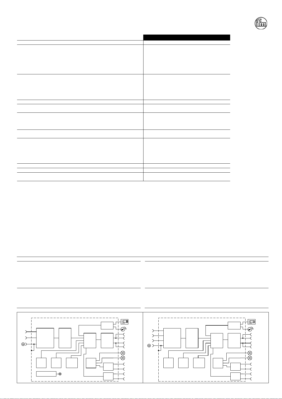
Indicators, LEDs
Overload LED DC-OK LED DC-OK Contact
Normal mode OFF ON Closed
During BonusPower®OFF ON Closed
Overload ON or flashing OFF Open
Output short circuit ON or flashing OFF Open
Temperature Shut-down flashing OFF Open
A
ctive Shut-down input flashing OFF Open
Anzeigelampen
Overload LED DC-OK LED DC-OK Contact
Normalbetrieb AUS EIN geschlossen
Während BonusPower®AUS EIN geschlossen
Überlast EIN oder blinken AUS offen
A
usgangskurzschluss EIN oder blinken AUS offen
Temperaturabschaltung blinken AUS offen
A
ktiver „shut-down“ Eingang blinken AUS offen
Fig. 3 / Bild 3 Insulation / Isolation Fig. 4 / Bild 4 Derating / Leistungsrücknahme Fig. 5 / Bild 5 Shut-down Input / Eingang Fig. 6 / Bild 6 DC-OK-Signal
AD
C
B
B*)
Lx/N
Input DC-ok
Earth Output
-
+/-
Shut-down
B*) When testing input to DC-OK connect al DC-OK pins
and the output pins together.
Allowed Output Current
0-25 0 20 40 70°C
10A
20A
30A
40A
50A
60A
continuous
60
Ambient Temperature
short-term(4s)
OFF: linked /
verbunden
ON : open / offen
Option A:
OFF: I > 0.3mA
ON : I < 0.1mA
Option B:
(open collector)
OFF: U < 1V
ON : U > 4V
Option C:
(ext. voltage /
ext. Spannung)
15
16
Shut-
down
Input
15
16
Shut-
down
Input
-
I
n.c. 15
16
Shut-
down
Input
-
+
U
n.c.
250ms
90%
V
ADJ
<
1ms
10%
open
V
OUT
=
V
ADJ
openclosed closed
>
1ms
Fig. 7 / Bild 7 Output Characteristic / Ausgangskennlinie Fig. 8 / Bild 8 E84016, E84036 Dimensions / Abmessungen
Output Voltage
(Single Use, typ.)
22V 02040
23V
24V
25V
29V
26V
27V
28V
60A503010
Adjustment Range
Output Current
Factory
setting
AB
AB
A
B
Short-term (4s)
BonusPower
Continuously
available
Output Voltage
(Parallel Use, typ.)
22V 02040
23V
24V
25V
29V
26V
27V
28V
60A503010
Adjustment Range
Output Current
Factory
setting
AB
AB
A
B
Short-term (4s)
BonusPower
Continuously
available
PU-374.010.22-10A

This manual suits for next models

1

Other IFM Electronic Power Supply manuals

IFM Electronic DN1023 User manual

IFM Electronic

IFM Electronic DN1023 User manual

IFM Electronic DN4033 User manual

IFM Electronic

IFM Electronic DN4033 User manual

IFM Electronic ecomat200 DN301 Series User manual

IFM Electronic

IFM Electronic ecomat200 DN301 Series User manual

IFM Electronic dn1030 User manual

IFM Electronic

IFM Electronic dn1030 User manual

IFM Electronic AS-Interface AC1254 User manual

IFM Electronic

IFM Electronic AS-Interface AC1254 User manual

Popular Power Supply manuals by other brands

Pulsar PSBSH 1012A manual

Pulsar

Pulsar PSBSH 1012A manual

Whelen Engineering Company UPS188C installation guide

Whelen Engineering Company

Whelen Engineering Company UPS188C installation guide

Inogen BA-107 Instructions for use

Inogen

Inogen BA-107 Instructions for use

artisan T800 Series Service manual

artisan

artisan T800 Series Service manual

Meech Hyperion 907 operating manual

Meech

Meech Hyperion 907 operating manual

BCP PUOOUCSV How to install

BCP

BCP PUOOUCSV How to install

Velleman LABPS3005DN user manual

Velleman

Velleman LABPS3005DN user manual

Horizont Agrar hobbygard N 104271 Operating	 instruction

Horizont Agrar

Horizont Agrar hobbygard N 104271 Operating instruction

Antec EARTHWATTS EA-380 user manual

Antec

Antec EARTHWATTS EA-380 user manual

Pulsar 276V/7A/2x17Ah/LCD manual

Pulsar

Pulsar 276V/7A/2x17Ah/LCD manual

Matrix MPS-6003LP-3 user manual

Matrix

Matrix MPS-6003LP-3 user manual

Altronix AL1024NK8QP Series installation guide

Altronix

Altronix AL1024NK8QP Series installation guide

Altronix TROVE T2MK34 installation guide

Altronix

Altronix TROVE T2MK34 installation guide

Sun Power SPS-G015 Series user manual

Sun Power

Sun Power SPS-G015 Series user manual

KEPCO JBW 5-20K Operator's manual

KEPCO

KEPCO JBW 5-20K Operator's manual

KEPCO KLR SERIES quick start guide

KEPCO

KEPCO KLR SERIES quick start guide

Corsair AXi Series manual

Corsair

Corsair AXi Series manual

Meanwell IRC1 instruction manual

Meanwell

Meanwell IRC1 instruction manual

manuals.online logo
manuals.online logoBrands
  • About & Mission
  • Contact us
  • Privacy Policy
  • Terms and Conditions

Copyright 2025 Manuals.Online. All Rights Reserved.