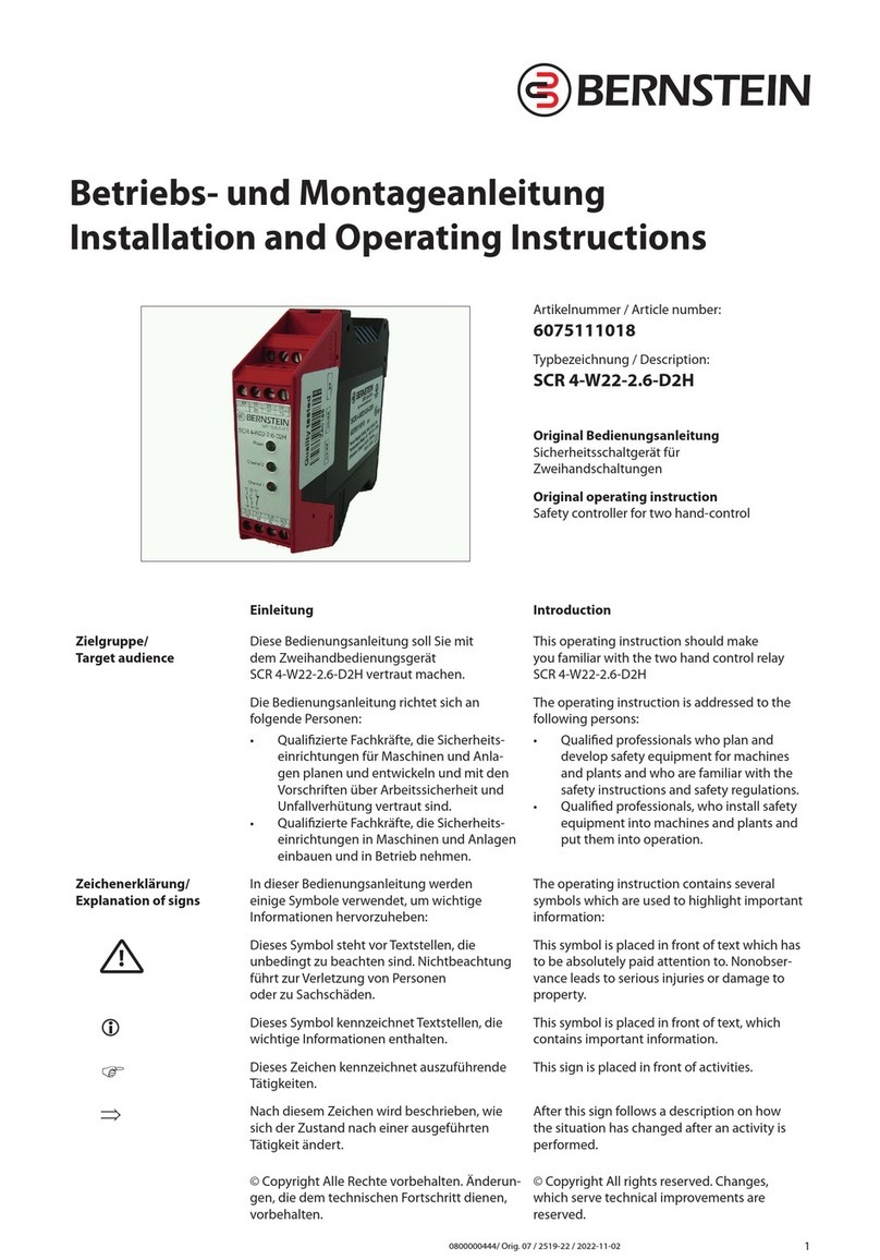
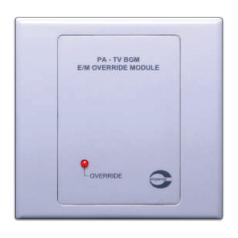
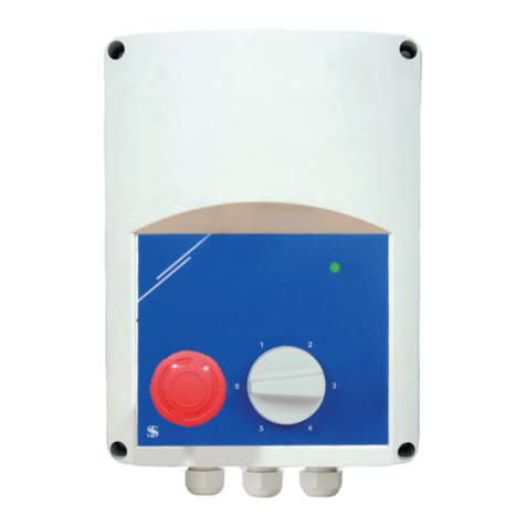
BERNSTEIN SCR OM User manual

Muting controller
with Relay Outputs
SCR OM
Special characteristics:
- Intended for use with Bernstein light curtains
- Muting controller for presence sensing safeguarding devices according to EN 61496-1
- For applications up to safety category 4 according to EN 954
- Connection of an external muting light according to EN 61496-1
- Connection of different muting-sensors (NPN, PNP and relay outputs)
- Monitoring of external contactors and expansion modules
- Housing with detachable terminal strips
CE
1
Art.-Nr.: 6562321009
Original: 01
Benennung: SCR OM 24VDC
Mittl.Nr.: 0089-07
Datum: 13.02.2007

WARNING
Bernstein safety systems are intended to protect operators
working at or near dangerous machinery. They can only
perform this function if they are correctly fitted to a suitable
machine. It is essential that the full contents of this manual
and all the authoritative documents referred to herein are
fully understood before any attempt at installation is made.
If in doubt contact your authorised Bernstein distributor.
The safety of persons and equipment cannot be guaranteed
if the muting controller is not used in accordance with its
intended use.
IMPORTANT
This manual must accompany the product throughout its
working life. Those persons responsible for the product must
ensure that all persons involved in the installation,
commissioning, operation, maintenance and servicing of the
product have access to all the information supplied by the
manufacturers of the machine and its safety system.
PLEASE OBSERVE THE FOLLOWING:
The device may only be installed and commissioned in compliance with these operating instructions
by suitably qualified personnel familiar with working safety and accident prevention legislation.
Electrical work may only be performed by suitably qualified electricians.
Repairs, in particular those involving opening the housing, may only be performed by the
manufacturer or persons authorised up by the manufacturer. Any attempt to perform repairs by
unauthorized persons will invalidate the warranty.
Please observe the relevant valid regulations, in particular those pertaining to safety measures and
the installation of muting sensors, the muting lamp and the Bernstein light curtain.
It must be possible to view the danger area from the installation location of the start button and the
key-operated switch.
It must not be possible to start the equipment from the danger area.
2

Explanation of terms
Muting Temporary by passing of a Light Curtain in order to transport
material into or out of the danger area.
Restart inhibit Prevention of machinery from automatically resuming
operation.
Introduction
The Bernstein SCR OM muting controller with relay outputs is designed to be used with the new generation of
Bernstein safety light curtains, to safeguard operators from dangerous machinery up to safety category 4 as
described in EN 954-1. The integrated muting function, which has been designed to EN 61496, permits goods
to be transported into or out of the danger area without impairment to the safety function.
The SCR OM provides a safe method of providing a muting function, by the appropriate use of carefully
positioned sensors, either two or four, at the entrance / exit of the danger area, in such a way that only the
material being transported activates the sensors. Once the material has activated the muting sensors, the
SCR OM then initiates the muting cycle for the period during which the material is being transported through
the protected field.
The muting sensors are arranged in such a way as only the material can correctly activate the muting sensors,
and any person approaching the danger area will cause a shut down of the safety system.
A basic overview of the muting application is shown in the diagram below:
MS1
ML
MS2 MS3
Danger area
MS4
EST ESS
MS1, MS2, MS3, MS4 Muting sensors ML Muting lamp
EST Start button ESS Key-operated switch
3

Operation
The SCR OM functions in the following way:
To initiate a muting cycle, muting sensors MS1 and MS2 have to be activated within 3 seconds of each other.
The muting lamp will turn on, and any interruption of the light curtain will not cause the outputs of the
SCR OM to de-activate. Once three of the four muting sensors have been cleared, the muting cycle will
terminate after a time period of 0.25 seconds, and the light curtain will no longer be bypassed.
1
a
i
i
a
i
a
i
a
i
a
i
a
Muting
a: active
b: inactive t<3s t<3s
0,25 s
ML
MS4
MS3
MS2
MS1
Signal must be overlapping, i.e. both
muting sensors must be active at the same time
MS1
ML
MS2 MS3
MS4 MS1
ML
MS2 MS3
MS4
MS1
ML
MS2 MS3
MS4 MS1
ML
MS2 MS3
MS4 MS1
ML
MS2 MS3
MS4
t1 t2 t3 t5
It is possible to use only two retro-reflected type mute sensors, if they are arranged diagonally across the field
of the light curtain, with the cross over point on the dangerous side of the light curtain, as shown below:
MS1 MS1
MS2 MS2MS3
MS4
4

Indicators
Five indicators on the front panel of the SCR OM are used to indicate the control units status.
1Power ON
2Fault
3 Restart inhibit on, waiting for start
4Operation – Channel 1 activated
5Operation – Channel 2 activated
4+5 flashing Error code (See Section XXX)
5

Connection Details
The following terminals are available on the SCR OM muting control unit
Terminals Description
A1+ , A2- Supply Voltage
EST+, EST Start/Restart button
ESS+, ESS Key-operated switch (Mute Over-ride)
ESS+, 53 Muting lamp
AML Not used for muting operation
ERK+, ERK Feedback circuit
MSx+ Positive voltage for muting sensor x
MSx- Negative voltage for muting sensor x
MSxP Input of muting sensor x -PNP
MSxN Input of muting sensor x -NPN
BWSE+ Positive voltage for light curtain signals
BWSE- Negative voltage for light curtain signals
BWSxP Input of light curtain channel x - PNP
BWSxN Input of light curtain channel x - NPN
13-14, 23-24, 33-34 Relay safety outputs
63-64 Light curtain enable output
54 Negative internal supply voltage (internally
connected to EST-, ESS-, ERK-, BWSE-, MSx-)
73-74 Auxiliary mute indicator output
OP, O1, O2 Optocoupler outputs
6

System Components
Muting lamp
During material transport through the protected field, the muting controller switches the muting lamp (ML) on.
The SCR OM monitors the filament of the muting lamp even when the muting function has not yet been initiated.
If the filament is defective, or if no lamp is connected, the control unit goes to lockout and the safety outputs are
switched off.
In accordance with EN 61496-1, the following conditions must be adhered to for the muting lamp.
The luminous surface must be at least 1cm² and have a brightness of at least 200cd/m².
Muting sensors
Mechanical, inductive, capacitative and optoelectronic sensors are suitable as muting sensors; either solid-state
outputs or relay outputs can be used.
1. The muting sensors must have a rated voltage of 24 V DC at the output.
Key-operated switch (Mute Over-ride)
A key operated switch is connected to the SCR OM to allow the user to manually activate of the mute cycle,
regardless of the status of the mute sensors, for example, when the material is already located in the area
monitored by the muting sensors, and the control unit outputs are de-activated.
The muting cycle remains active as long as the key-operated switch is actuated, for a maximum time of ten
minutes.
As soon as the muting sensors have been cleared, the key switch is released, and the system restarted with the
Start/Restart button
7

Outputs
The muting controller has the following outputs:
Three N/O safety relay outputs (13-14, 23-24, 33-34)
One N/O auxiliary mute lamp output (73-74)
Two auxiliary optocoupler outputs (OP-O1, OP-O2)
Optocoupler output O1 switches to 24V when the safety outputs are active.
Optocoupler output O2 switches to 24V when the connected light curtain is interrupted.
Mechanical Installation
Dust and moisture can lead to malfunctions. Install the device in a dust and damp-proof housing, for
example in a switch cabinet or a IP54 housing.
Mount the muting controller on a universal mounting rail DIN EN 50022 as shown below:
OP
O1
24 V DC
8

Electrical Installation
Important Information
Short circuits, broken cables, power failure or voltage fluctuations in the network can impair and/or cancel
the safety function and result in serious accidents.
The safety output leads and, if they are the same polarity, also the leads of the two muting sensor
groups must be laid in separate non-metallic-sheathed cables.
The power supply to the device and all connections must be reliably isolated from the mains, by using
an isolating transformer in accordance with IEC 60742 .
Muting sensors
Muting sensors are wired depending on the operating mode, type and number of sensors. Either 2 or 4 muting
sensors must be connected to the muting controller. When using two muting sensors, these must be connected
to terminals MS1... and MS2... .
Connect the muting sensors in accordance with the diagrams below:
MSxP and MSxN must always be connected on the SCR OM.
The unused connections on the SCR OM must be connected as follows:
If MSxN is not used, connect MSx- to MSxN
If MSxP is not used, connect MSx+ to MSxP
Please Note
1. If 4 muting sensors are connected, sensors with the same polarity must be used at the connections
MS1.. and MS4.. / at MS2.. and MS3.. .
2. The wiring for MS1../MS4.. and MS2../MS3.. must be in separate cables.
9

Light Curtain
The Bernstein Light curtain is to be connected to the SCR OM as shown below:
Power supply, Mute Over-ride key switch, Muting lamp, Start button
Connection of the supply voltage, mute over-ride, mute lamp and start button is as follows:
Only connect the operating voltage to terminals A1+ and A2- when the remaining wiring has been
completed.
10

Safety Outputs
The terminals 13-14, 23-24 and 33-34 are safety relay outputs. If the muting controller is running and the light
curtain is unobstructed, the outputs will be activated.
To extend the safety outputs, relays with positive guided contacts must be used
The use of external relays without spark suppressors can lead to damage to the muting controller. For
this reason, always connect protection diodes, e.g. Type 1N4007, in parallel with any external relay coils.
11

Commissioning and Testing
After applying the supply voltage, the SCR OM performs an internal self-test.
LED’s 1,3,4 and 5 light up, and the SCR OM can then be activated by pressing the start button, and the outputs
should activate.
If the self-test has not been successfully executed, there could be a fault or a connection error. For details, see
the following section "Troubleshooting".
Troubleshooting
The muting controller is equipped with comprehensive a diagnostics functions. If a fault is present, the fault LED
will flash, together with the LEDs from channel 1 and channel 2. It is possible, under certain circumstances for
both channel LEDs to indicate different errors. From the number of flashes (flashing code), it is possible to
determine which fault has occurred (See following table for flash codes).
Example:
Netz
Power
Kanal 1
Channel1
Kanal 2
Channel2
Störung
Fault
Channel 1 LED flashes 9 times (code 9), Channel 2 LED flashes once (code 1)
Channel 1 LED indicates the fault "Muting lamp interrupted"
Channel 2 LED indicates the fault "Inequality of the two channels".
Tip: If both channel LEDs flash, the code can be more easily read by covering the other LED.
If an error occurs, check the supply voltage between terminals A1+ and A2-. This voltage must not drop
below 21.6 V DC.
12

Fault Diagnosis Chart
FC Fault Possible cause What to do
1 Differences between the channels Only one Channel detects an Error Look at the Flash Code of the other channel
2 One of the channels activates One channel faulty Reset system
3 Feedback circuit open Normally closed contacts of external
relays are not connected
Link not wired
Check wiring
Check external relays
4 Start button constantly activated Start button faulty
Start switch is used instead of start push
button
Check start button on short circuit
Check start button (must be a momentary push
button)
5 Key switch is activated during start up Key switch activated
Key switch defect
Reset system
Check key switch
6 Light curtain active on start up Wiring error of the light curtain Check wiring; emitter test signal must activated
with output 63-64.
7 Internal fault of the safety output Wiring error of safety outputs
Noise on the control line
Output faulty
Check wiring of safety outputs.
8 Internal fault of emitter control Wiring fault of the light curtain
Noise on control line
Output fault
Check wiring of output 63-64.
9 Muting lamp disconnected Muting lamp faulty
Muting lamp is missing
No link on AML terminals
Check muting lamp and change if necessary
Insert link between AML terminals
10 Key switch activated twice After the clearance of the light barrier
the key switch was activated a second
time
Reset system
11 Light curtain disconnected during start or
time out on receiver
Wiring fault for the light curtain
Optical Path is broken
Timeout reached
Check wiring
Check optical path
Check technical data of the light barrier (start
time, power consumption)
12 Simultaneousness of muting sensors
exceeded (3s)
Wrong position of the muting sensors
Only one muting sensor was activated
Check position of muting sensors, the material
must activate both sensors within 3s
all muting sensors wired ?
13 Internal fault of muting lamp control Wiring fault of the muting lamp
Muting lamp defect
PIN 53 is connected to GND
Output fault
Check wiring at PIN 53 and ESS+
Check muting lamp
14 Mute Over-ride timeout exceeded Manual muting timeout (10 min)
reached
Reset System
15 Internal memory fault Noise on control / Power lines
Internal error
Reset; if fault occurs again: check system for
noise
13

Technical data
Electrical data
Supply voltage Uv 24 V DC
Voltage range 0,90 ...1,1 Uv
Maximum ripple ≤5%
Power consumption without peripheral devices appr. 10 W
Conductor connection 1 x 4,0 mm2wire
2 x 1,5 mm2wires
Safety Outputs 3 N/O contacts
Switching voltage 24 V DC
Response time (light curtain) < 20 ms
Input current appr. 15 mA for each input
Simultaneousness of muting sensors 3 s
Muting time max. 10 minutes mute over-ride, infinite during normal operation
Startup waiting time max. 6 s
Switching current, outputs 13-14, 23-24, 33-34 6 A continuous current (one output loaded)
3,5 A continuous current (three outputs loaded)
Output 63-64 (curtain enable) N/O Relay 2 A / 24 V DC
Output 7374 (auxiliary mute lamp) N/O Relay 1,2 A / 24 V DC
Output OP-O1, OP-O2 Optocoupler, 20mA /24 V DC
Power supply - muting sensors Together max. 0,5 A (24 V DC)
Output 53 (muting lamp) 24 V DC, max. 1 A
Mechanical data
Housing material Self extinguishing according to UL 94 V-0
Dimensions (WxHxD) 90x84x121 mm
Mounting Snap mounting on universal mounting rail NS35 according to
DIN EN 50022
Environmental data
Environment temperature -25°C ... +55°C
Humidity Operation 75% (non condensing), Storage 85% (non condensing)
Creepage and clearance DIN VDE 0110 part 1 at pollution grade 2, basic isolation: over voltage
category 3; safe breaking: over voltage category 2
Terminal type IP 20
Housing type IP 40
Shock resistance < 0,7 Nm
Vibration resistance Frequency < 33 Hz, Amplitude < 0,35 mm
beantragt
Mounting rail
DIN EN 50022
90
84
80
113
118
14
Table of contents
Other BERNSTEIN Controllers manuals
