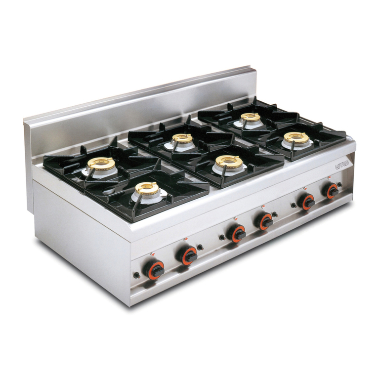
Bertos LXG9CP-SG9CP-G9CP User manual

cod. 31876500
INSTRUCTION MANUAL GAS PASTA COOKER Original instructions)
Attention: read the instructions before using the appliance.
EN

|2
MOD.
VkW: Hz: 50/60 IP
Qn
N°:
EN
These types of appliances are designed for commercial applications such as restaurant kitchens,
cafeterias, canteens, hospitals and businesses such as bakeries, butcher shops, etc., but not for
the continuous mass production of food.
The appliances require that some precautions are made during the installation, positioning and/
or xing and connection to the mains. See the paragraphs titled“ELECTRICAL CONNECTION”and
“PUT INTO SERVICE”.
The appliances require certain precautions during their use and operation. See the “INSTRUC-
TIONS FOR USE”paragraph.
The appliance must not be cleaned with water jets or steam cleaners.
Warning!
Before carrying out any work, turn o the general power supply
For the direct connection to the mains, provide a device that ensures the disconnection from
the mains with a contact opening distance that allows for the complete disconnection under
category III overvoltage conditions in compliance with the installation rules.
If the power cable is damaged, it must be replaced by the Manufacturer or itsTechnical Support
or a qualied person.
Equipotential bonding
The appliance must be connected to an equipotential system.The connecting terminal is posi-
tioned in the immediate vicinity of the power cable entry.
It is marked with the following symbol:
Maintenance shall be carried out by qualied personnel.
To avoid damage, don’t use direct water jets towards the appliance.

3||
ITALY
MODEL:
TYPE:
FITTED TO:
A
D
C
B
ITALY
MODEL:
TYPE:
FITTED TO:
A
D
C
B
1
3 4
2
5
68
4
7F
21
2
H
G
N
E
H
L
M
D
CB
1
5
10
3
2
19 18
H
FG
T
FGP
TP_700_40
TP_700_80
TP_900_80
1
Ø 51 mm
H
11
36
35
36
A
H
A
2
2423
25 26
24
25 26
1
E
D
G
I
B
C
F
4
3
A - Parte superiore del bruciatore
B - Ugello
C - Anello a doppio cono
D - Candele di accensione
E - Termocoppia
F - Vite per il condotto del gas
G - Vite per la candela di accensione
I - Vite per la termocoppia
regolazione aria - air adjustment
réglage de l’air - luftregelung
regulación aire - luchtregulatie
regulação do ar - βάνα ρύθμισης αέρα
seřízení vzduchu - regulácia vzduchu
levegőszabályozó - luftregulering
justering av luft - luftreglering
regulacja powietrza - reglare aer
FG T
FG1
FG FGP
15
14
16

MOD.
VkW: Hz: 50/60 IP4
Qn
N°:
4|
MOD.
VkW: Hz: 50/60 IP4
Qn
N°:
PASTA COOKER BURNER
LXG9CP - SG9CP -
G9CP
PASTA COOKER BURNER
CPG - SG7CP
PASTA COOKER BURNER
G6CP6
Rated output per burner kW 12 10 10
Reduced power per burner kW 4,8 3,4 3,4
EN
BURNERS
Gas type Burner Ø Injectors Ø By Pass Primary air
adjustment Ø Pilot
burner
GAS G20 20mbar
PASTA COOKER LXG9CP - SG9CP - G9CP
250R Adjustable 33 mm 27 .2
METHANE PASTA COOKER CPG - SG7CP 230R Adjustable 33 mm 27 .2
PASTA COOKER G6CP6 225R Adjustable Open 41
II2H3+
SUPPLY PRESSURE:
(min÷max)
G20 17÷25 mbar
GAS G30/G31
PASTA COOKER LXG9CP - SG9CP -
G9CP 175 100 36 mm 22
28-30/37mbar PASTA COOKER CPG - SG7CP 160 100 31 mm 22
LPG PASTA COOKER G6CP6 145R 100 Open 25
II2H3+
SUPPLY PRESSURE:
(min÷max):
G30 25÷35 mbar
G31 25÷45 mbar

|5
SG7CP40M
220-240V~ 50Hz

MOD.
VkW: Hz: 50/60 IP4
Qn
N°:
6|
MOD.
VkW: Hz: 50/60 IP4
Qn
N°:
G6CP6 CPG40E
G6CP6
720
600
272 (1/2" G)
271 (3/4" IN H2O)
413 (3/4" OUT H2O)
97 (1/2" G)
15 (1/2" G)
274 (3/4" OUT H2O)
133 (3/4" OUT H2O)
112 (3/4" IN H2O)
25 (3/4" IN H2O)
600 140
1040
12040
600
CPG40E
400
700
400
216 (1/2" G)
700
31 (1/2" G)
100 (1/2" G)
140
1040
14055
216 (3/4" IN H2O)
284 (3/4" OUT H2O)
119 (3/4" IN H2O)
38 (3/4" IN H2O)
104 (3/4" OUT H2O)
135 (3/4" OUT H2O)

MOD.
VkW: Hz: 50/60 IP4
Qn
N°:
|7
MOD.
VkW: Hz: 50/60 IP4
Qn
N°:
CPG80E G9CP40

MOD.
VkW: Hz: 50/60 IP4
Qn
N°:
8|
MOD.
VkW: Hz: 50/60 IP4
Qn
N°:
G9CP80 SG9CP40

MOD.
VkW: Hz: 50/60 IP4
Qn
N°:
|9
MOD.
VkW: Hz: 50/60 IP4
Qn
N°:
SG9CP80 LXG9CP40

MOD.
VkW: Hz: 50/60 IP4
Qn
N°:
10 |
MOD.
VkW: Hz: 50/60 IP4
Qn
N°:
SG7CP40M

MOD.
VkW: Hz: 50/60 IP4
Qn
N°:
|11
EN
Instruction manual
Dimensions 12
Technical data 13
Specic instructions 15

MOD.
VkW: Hz: 50/60 IP4
Qn
N°:
12 |
EN
GAS PASTA COOKER - SERIES PLUS 600
GAS PASTA COOKER - SERIES MACROS 700
GAS PASTA COOKER - SERIES MAXIMA 900
GAS PASTA COOKER - SERIES S900
GAS PASTA COOKER - SERIES S700
GAS PASTA COOKER - SERIES LX900 TOP
Model Description Dim.: (LxWxH)
work surface (h total)
G6CP6 Gas pasta cooker with cabinet mm 600x600x900 (1020)
Model Description Dim.: (LxWxH)
work surface (h total)
CPG40E Gas pasta cooker with cabinet mm 400x714x900 (1040)
CPG80E Gas pasta cooker with cabinet - 2 tanks mm 800x714x900 (1040)
Model Description Dim.: (LxWxH)
work surface (h total)
G9CP40 Gas pasta cooker with cabinet mm 400x900x900 (1065)
G9CP80 Gas pasta cooker with cabinet - 2 tanks mm 800x900x900 (1065)
Model Description Dim.: (LxWxH)
work surface (h total)
SG9CP40 Gas pasta cooker with cabinet mm 400x900x900 (1060)
SG9CP80 Gas pasta cooker with cabinet - 2 tanks mm 800x900x900 (1060)
Model Description Dim.: (LxWxH)
work surface (h total)
SG7CP40M Gas pasta cooker with cabinet mm 400x730x900 (1090)
Model Description Dim.: (LxWxH)
work surface (h total)
LXG9CP40 Gas cantilever pasta cooker mm 400x900x580 (740)

MOD.
VkW: Hz: 50/60 IP4
Qn
N°:
|13
EN
TECHNICAL DATA TABLE
TECHNICAL DATA TABLE
TECHNICAL DATA TABLE
GAS PASTA COOKER - SERIES PLUS 600
GAS PASTA COOKER - SERIES MACROS 700 - S700
GAS PASTA COOKER - SERIES MAXIMA 900 - S900 - LX900
TECHNICAL DATA TABLE
GAS PASTA COOKER
-
ELECTRIC IGNITION
MODEL
Rated
power Reduced
power Rated
power
G110
Rated
power
G120
LPG
consump.
G30
LPG
consump.
G31
Methane
consump.
G20
Methane
consump.
G25
Methane
consump.
G25.1
Methane
consump.
G2.350
Methane
consump.
G27
City Gas
comsump.
G110
City Gas
comsump.
G120
Primary air
combustion Installation
type Burner
kW kW kW kW kg/h kg/h m³/h m³/h m³/h m³/h m³/h m³/h m³/h m³/h n°kW
G6CP6 10 3.4 9.5 10 0.79 0.78 1.06 1.23 1.23 1,47 1.29 2.45 2.30 20 A1 1 10
MODEL
Rated
power Reduced
power Rated
power
G110
Rated
power
G120
LPG
consump.
G30
LPG
consump.
G31
Methane
consump.
G20
Methane
consump.
G25
Methane
consump.
G25.1
Methane
consump.
G2.350
Methane
consump.
G27
City Gas
comsump.
G110
City Gas
comsump.
G120
Primary air
combustion Installation
type Burner
kW kW kW kW kg/h kg/h m³/h m³/h m³/h m³/h m³/h m³/h m³/h m³/h n°kW
CPG40E
SG7CP40M 10 3.4 8 9 0.79 0.78 1.06 1.23 1.23 1,47 1.29 2.07 2,07 20 A1 1 10
CPG80E 20 6,8 16 18 1.58 1.55 2.12 2.46 2.46 2,94 2.58 4.13 4.13 40 A1 2 10
MODEL
Rated
power Reduced
power Rated
power
G110
Rated
power
G120
LPG
consump.
G30
LPG
consump.
G31
Methane
consump.
G20
Methane
consump.
G25
Methane
consump.
G25.1
Methane
consump.
G2.350
Methane
consump.
G27
City Gas
comsump.
G110
City Gas
comsump.
G120
Primary air
combustion Installation
type Burner
kW kW kW kW kg/h kg/h m³/h m³/h m³/h m³/h m³/h m³/h m³/h m³/h n°kW
G9CP40 - SG9CP40
LXG9CP40 12.5 4.8 / / 0.99 0.97 1.32 1.54 1.54 1.84 1.61 / / 25 A1 1 12.5
G9CP80 - SG9CP80 25 9.6 / / 1.97 1.94 2.65 3.08 3.07 3.68 3.23 / / 50 A1 2 12.5
MODEL Rated power Rated voltage Connection cable - H07RN-F
Watt V mm2
SG7CP40M 0.6 220-240 V~3 x 1,5 mm2

MOD.
VkW: Hz: 50/60 IP4
Qn
N°:
14 |
EN
The units are in conformity with the European regulations, directives and standards:
Reg. 1935/2004/CE Regulations governing materials and items in contact with food products
Reg. 2016/426/UE Regulation on appliances burning gaseous fuels
2014/35/UE Low voltage
2014/30/UE EMC (electromagnetic compatibility)
2011/65/UE Restriction of the use of certain hazardous substances in electrical and electronic equipment
EN 203-1 General safety standard for GAS appliances for domestic and similar use.
EN 203-2-11 Gas heated catering equipment – Specific requirements – PASTA COOKERS
EN 55014 Requirements for electromagnetic compatibility
EN 60335-1 General Standard on the safety of household and similar electrical appliances
EN 60335-2-102 Special standard on the safety of gas appliances with electrical connections.
EN 61000 Requirements for electromagnetic compatibility
Unit features
The serial number plate is positioned on the front side of the unit and contains all the connection data.
Serial: ........../..........TYPE/MOD: ........../..........
kW: ..........
kW: ..........
V: ..........
IPX: ..........
0051-.....
Made in Italy
Cert: 51..........
TYPE: A1 Hz: 50/60
NAME:
MANUFACTURER’S ADDRESS:
INFORMATION FOR USERS OF PROFESSIONAL APPLIANCES
Pursuant to Article 24 of Legislative Decree no. 49 of 14 March 2014,
"The Implementation of EU Directive 2012/19 on Waste Electrical and Electronic Equipment (WEEE)".
The crossed out wheelie bin on the appliance or its packaging indicates that the end-of- life product must be collected
separately from other waste, in order to ensure proper treatment and recycling.
In particular, the separate collection of professional end-of- life appliances is organised and managed:
a) directly by the user, if the appliance was placed on the market under past WEEE systems and the user decides to
dispose of it without replacing it with another similar appliance with the same functions;
b) by the manufacturer, i.e. the party who first introduced and commercialised in EU countries, or sold in EU countries,
under its own brand, the new appliance that replaced the previous one, when, after making the decision to dispose
of an end-of- life appliance placed on the market under past WEEE systems, the user purchases a similar appliance
with the same functions. In this case, the user may ask the manufacturer collect the old appliance no later than 15
consecutive calendar days after the delivery of the new appliance;
c) by the manufacturer, i.e. the party who first introduced and commercialised in EU countries, or sold in EU countries,
under its own brand, the appliance, when the appliance was placed on the market under new WEEE systems.
The proper separate waste collection for the subsequent forwarding of the decommissioned product for recycling,
treatment and environmentally compatible disposal, helps prevent negative impact on the environment and health, and
promotes the reuse and / or recycling of the materials that the appliance is made of.
The user’s illegal disposal of the product will result in the application of sanctions set out in current regulations.

MOD.
VkW: Hz: 50/60 IP4
Qn
N°:
|15
EN
- building regulations and local fire prevention
measures;
- accident prevention regulations in force;
- local Gas Board regulations;
- CEI provisions in force;
- Fire Brigade provisions.
INSTALLATION
Assembly, installation and maintenance must all
be done by contractors authorized by the local Gas
Board in accordance with the regulations in force.
Installation procedures
To level the appliance correctly, adjust the height of
the four adjustable feet.
Gas connection
The ¾” or 1/2” G gas pipe union can either be
permanently fixed or detached by using a standard
adaptor. If a flexible tube is used, it must be made of
stainless steel and in conformity with regulations.
After completing the connection, check for leaks by
using a special leak-detector spray.
Exhaust system
The appliances must be positioned in locations
fitted with a system for discharging the products
of combustion in accordance with the installation
regulations. Our appliances are classified (see the
"TECHNICAL DATA” table) as:
“A1” gas appliances
They are not designed to be connected to a line for
the discharge of combustion products.
These appliances must discharge the combustion
products into the appropriate hoods, or similar
devices, connected to a flue of proven efficiency, or
they may be connected directly to an outdoor vent.
If such an arrangement is not possible, the unit may
be connected to an air exhaust system which leads
directly outdoors, having a capacity no lower than
required; see the“TECHNICAL DATA”table, plus the
air exchange necessary, in order to make operators
APPLIANCE DESCRIPTION
Sturdy steel structure with 4 height-adjustable
feet. External coating in 18/10 chrome-nickel steel.
Heating by tubular burners, resistant to thermal or
mechanical stresses.
Ideal for cooking pasta, rice, vegetables and
eggs, thanks to the rapid boiling of the water.
The water load, positioned in the front part of the
top, facilitates the regulation of the water flow
and ensures cleaning in the tank, facilitating the
disposal of starch and residues. The pressed tank
in AISI 316 steel, characterized by large rounded
edges, is equipped with a false bottom for
supporting the large baskets. The rack ensures a
large and comfortable support surface.
PREPARATION
Location
The appliance should be installed in a well-
ventilated room and, if possible, under a range
hood. The appliance can be installed on its own or
alongside other equipment.
Keep it at a minimum distance of 100 mm from the
side walls and 100 mm from the back wall.
Any walls near the appliance (walls, decorations,
pieces of furniture, finishing, etc.) must be made
of a non-combustible material.
Place the appliance on a table or on a board made
of a non-flammable material. Before connecting
the appliance to the gas supply, check the data
plate to make sure that the appliance is fitted for
the type of gas available. If the appliance works
with a different type of gas, see the paragraph
titled“Running appliances on other types of gas”.
Law provisions, technical regulations and
directives
Before installing, check that the following
provisions are met:
- UNI CIG 8723 regulations
ATTENTION!
The figures in this chapter can be found in the initial pages of this manual.
MOD.
VkW: Hz: 50/60 IPX
Qn
N°:
SPECIFIC INSTRUCTIONS

MOD.
VkW: Hz: 50/60 IP4
Qn
N°:
16 |
EN
available locally.
If not, adapt the appliance to the gas family or
group required (see the paragraph titled “Running
the appliance on other types of gas”). Carry
out the start-up according to the Operating
Instructions.
Testing power rating
Use the nozzles for the rated output on the
appliances.
Capacity can be of two types:
- rated output, as given on the data plate;
- reduced.
Refer to the“BURNERS”table for these nozzles.
The gas supply pressure must be within the ranges
given in the“BURNERS”table.
The appliance will not work outside the specified
pressure thresholds.
If you wish to check the rated output further, you
may do so by using a gas meter according to the
“volumetric method”.
However, it is normally enough to simply check
that the nozzles are functioning correctly.
Checking input pressure (Fig. 1)
The input pressure should be measured by using a
gauge (min. resolution 0.1 mbar).
Remove the screw (A) from the pressure socket and
connect the gauge; after measuring, retighten the
screw so that it’s absolutely airtight (A).
IMPORTANT:The pressure must be checked with all
gas equipment connected and operating.
Check the power according to the volumetric
method
Using a gas counter and a chronometer, you can
measure the gas consumption in a given unit of
time. This value will be compared to the value of E,
which is calculated as follows:
E= Burner power
Gas heating power
It’s important that the power is measured when the
appliance is in a state of inertia.
Both rated and reduced powers, calculated at the
rated pressure value, are obtained by referring
to the "BURNERS" table. The value of gas heating
power can be requested from the local gas
company.
Checking the operation
Ensure that the type of used nozzles corresponds to
that shown in the“BURNERS” table. Check whether
the pressure reducer has a flow rate greater
than the sum of the consumption flow rate of all
comfortable.
ELECTRICAL CONNECTION
1) If it is not present, install a disconnector switch
near the equipment with a magneto-thermal
release and a locking differential.
2) Connect the switch disconnector to the terminal
block as given in the wiring diagrams.
3) The selected connection cable must have
characteristics not lower than the H07RN-F with
a temperature of use of at least 80° C and it must
also have a section suitable for the appliance
(see TECHNICAL DATA table).
4) Pass the cable through the hole and tighten the
cable clamp, connect the conductors in their
corresponding position in the terminal board
and fix them. The yellow-green earth conductor
must be longer than the others, so that, in case
of breakage of the cable clamp, it detaches after
the voltage cables
Equipotential bonding
The appliance must be connected to an
equipotential system. The connecting terminal is
positioned near the power cable entry.
It is marked with the following symbol:
MOD.
VkW: Hz: 50/60 IPX2
Qn
N°:
Connection to the water mains
Connect the water inlet pipe to the distribution
network, using a mechanical filter and a shut-off
valve.
Before connecting the filter, let a certain amount of
water flow out to purge the pipeline of any ferrous
waste.
If the inlet pressure exceeds 300 kPa, install a
pressure reducer.
Drain water
Connect the appliance’s drainpipe to the mains.
PUT INTO SERVICE
Before installation
Before installing the appliance, remove the
protective wrapping. Thoroughly clean the work-
surface and the outside of the appliance with
lukewarm water and detergent, using a soft cloth.
Dry with a clean rag.
Start-up
Before starting the appliance, make sure that its
specifications (category and type of gas used)
match those of the family and group of the gas

MOD.
VkW: Hz: 50/60 IP4
Qn
N°:
|17
EN
doors or by removing the control panel.
Remove the nozzles and replace them with suitable
ones according to the BURNERS table. Be careful to
keep and assemble the seal gasket, if any.
Regulation of PEL 21 minimum (Fig. 3)
Referring to the "BURNERS" table, adjust the
minimum gas flow adjustment screw (B) as follows:
- for LPG operations, tighten the minimum gas
flow adjustment screw up to the stop;
- for operations with natural gas:
1 Find the knob of the corresponding valve.
2 Ignite the burner and bring it to the minimum
position.
3 Adjust the minimum flow rate by turning
the gas flow adjustment screw (B) (Fig. 3):
by unscrewing, the flow rate increases; by
screwing, the flow rate decreases.
4 Once the flame that is considered suitable
for the minimum function has been reached,
check that it corresponds to the minimum
flow rate indicated in the "TECHNICAL DATA"
table; the check must be made according to
the "volumetric method" already described
above, which is:
5 Read the gas meter and, at the same time,
restart the chronometer.
6 After a few minutes, i.e. 10 minutes, stop the
chronometer and read the counter.
7 Calculate the amount of gas which has
passed in 10 minutes (i.e. it’s the difference
between the two readings), for example 2nd
reading - 1st reading = 30 liters (0.03m³).
8 Now calculate the power at the minimum
position, applying the formula of the
volumetric method (see the previous
paragraph). Power (kW) = consumption
(m³/h) x the heating power of methane.
9 If the power is lower than the value given in
the table, unscrew the minimum screw again
and repeat the check.
10 If the power is higher than the value given
in the table, tighten the minimum gas flow
adjustment screw again and repeat the
check. (9.45 kW / h). P (kW) = 30 liters X 60/10
X 9.45 kW / h = 1,700 kW.
Regulation of the pilot light (Fig. 4)
- The pilot light operates with nozzles and fixed
air. The only requested operation is to replace
the nozzles according to the gas type as follows:
-
Loosen the nut, pressing the biconical coupling (N.
14); remove it (N. 15) and the pilot nozzle (N. 16).
- Replace the pilot nozzle with the correct nozzle;
refer to the“BURNERS” table.
connected equipment. Check that the gas supply
pipes are adequate.
Checking the pilot light
When correctly adjusted, the pilot light will
completely surround the thermocouple; if it does
not, check to see if the used injector is suitable for
the type of gas.
Checking primary air (Fig. 2)
The regulation is made using the Venturi tube by
adjusting the“X”dimension given in the“BURNERS”
table and checking the appearance of the flame
which must be homogeneous, well ventilated and
not noisy.
Checking the functions
- Start the appliance;
- Check the gas pipes for leaks;
- Check the burner flame, even at the minimum
position.
Notes for the installer
- Explain and show how the appliance works to the
user according to the instructions, and hand him
the user’s manual.
- Remind the user that, in the event of any
structural alterations or modifications to the
room that houses the appliance, the appliance
functions must be rechecked.
CHECKING FOR GAS LEAKAGE
After the installation, make sure that there are no
gas leakages. Use some water with soap and brush
it on the joints and fittings; any small leakage will
be shown by means of soap bubbles.
Another way to check for a gas leakage is to make
sure that the meter, if any, over a period of about 10
minutes, does not signal any gas passage.
WARNING: never use an open flame to check for
gas leakages.
RUNNING THE APPLIANCE
ON OTHER TYPES OF GAS
The appliance is tested and set up for operations
with the type of gas given on the technical data
plate. If the gas for which the appliance is regulated
is different from that of the connection, it is
necessary to fit the appliance by carefully following
the instructions below:
Replacement of the burner nozzles
The nozzles are accessible by opening the cabinet

MOD.
VkW: Hz: 50/60 IP4
Qn
N°:
18 |
EN
and temperature.
- When running the appliance for the first time,
properly clean the tanks and the drilled boards
with warm water and detergent to eliminate the
film of protective oil that covers the tanks.
LOADING THE TANK
Make sure that the draining tap is closed. Use the
handle of the loading tap, if any, which is positioned
on the left of the appliance’s front panel.
DRAINING THE TANK
Drain the tank by rotating the draining tap knob
placed inside the cabinet under the combustion
chamber. In a few models, the draining tap is
positioned on the front panel.
IGNITION
Ignition of the pilot burner
Push in and rotate the tap knob counterclockwise
over to the pilot position (), await the neces-
sary time for the air to exit the pipes (only the first
time) and them press the piezoelectric button ( )
several times. For the SG7CP40M model, keep the
ignition button pressed. Through the proper hole
on the front of the combustion camera, make sure
that the pilot flame is ignited. When the flame is
switched on, keep the knob pressed for a few sec-
onds and then release it. If the flame switches off,
repeat the operation.
NOTE
In the event of a failure that causes the lack of the spark,
the ignition can be performed manually.
Keep the knob pressed in the position ()and bring a
small flame to the pilot burner by introducing it through
the inspection hole of the combustion chamber.
Pilot burner ignition
After switching on the pilot burner flame, turn the
knob of the tap to the maximum power position ().
The gas will reach the main burner, which will ig-
nite. To reduce the power of the burner, turn the
knob to the minimum position ( ).
TURNING OFF
To turn off the main burner, rotate the tap knob
clockwise until reaching the position ( ).
To turn off the appliance completely, rotate the tap
knob clockwise up to the position ( ).
WARNING AND ADVICE
- While cooking with the pasta cooker, keep the
- After replacing the pilot nozzle, retighten the
nut, pressing the biconical coupling (N. 14) with
the relevant biconical coupling (N. 15).
Primary air control (fig. 2)
The adjustment is made by means of the Venturi
tube by adjusting the "X" dimension shown in the
"BURNERS" table and checking the appearance
of the flame which must be homogeneous, well
ventilated and not noisy.
Once the setting has been changed, indicate the
new type of gas on the plate.
APPLIANCE SAFETY SYSTEMS
Safety valve: a thermocouple valve stops the gas
flow from reaching the main burner in the event of
the pilot flame going out.
To restore the operation, repeat the operations
relevant to igniting the pilot device.
Safety thermostat: stops the gas flow in the event
of serious anomalies. It is reactivated manually
and, to restore it, it is necessary to unscrew the nut
(A) (fig. 5). If the safety thermostat starts up, call
Technical Support.
OPERATING INSTRUCTIONS
We recommend that the user checks that the
installation is performed properly.
The Manufacturer is not responsible for
damage due to an incorrect installation, poor
maintenance or incorrect use or for changes of
the combustion system.
- The appliance is for industrial use and must be
used by trained personnel.
- This appliance must be used for the purposes it is
designed for. Every other use is incorrect.
- Do not use these appliances as fryers because
the oil temperature cannot be controlled and it
would overcome 230 °C with the risk of the oil
catching on fire.
- Do not use the appliance when the tank is empty.
- Do not modify the combustion aeration system.
- Before running the unit, READTHE INSTRUCTIONS
OF THIS MANUAL CAREFULLY, paying particular
attention to the regulations relevant to safety
devices.
- Always close the gas cocks after use and especially
during maintenance and any repair operations.
- Follow the cooking provisions carefully, at least
for the first period of use, until practice and
experience allow you to choose the cooking time

MOD.
VkW: Hz: 50/60 IP4
Qn
N°:
|19
EN
BY THE MANUFACTURER. The parts must be re-
placed by authorized personnel only!
For a few models, it is sufficient to remove the pan-
el by unscrewing the screws in view on the lower
edge or in the front to have access to the parts to
be replaced; for the other models, it is sufficient to
open the lower door.
ATTENTION: empty the tank before removing
the panel and replace the components.
- Valved tap: all fittings are on view. Use suitable
wrenches to unscrew the gas inlet and outlet fit-
tings, pilot nozzle and thermocouple. Replace the
tap with a new one and reconnect the pilot noz-
zle and the thermocouple.
- Burner: to replace the burner, unscrew the nut,
pressing the biconical coupling from the nozzle
holder fitting, unscrew the two screws that fix the
burner to the combustion chamber and extract
the burner. Remove from the burner bracket from
the nozzle holder fitting by unscrewing the fixing
nut and assemble it in the new burner. Repeat all
operations in reverse and reassemble everything.
- Thermocouple: loosen the nut that fixes the
thermocouple to the pilot burner and extract
the thermocouple from its seat. Unscrew the nut
fixing the thermocouple to the tap. Replace the
thermocouple and reassemble everything.
- Plug: remove the cable and unscrew the fixing
nut. Assemble the new plug, paying attention not
to tighten the nut too much because the insulat-
ing ceramic might be damaged.
- Flexible water supplying pipe: in the event of
a replacement, make sure that the pipe does not
lay on the combustion chamber.
APPLIANCE CARE
ATTENTION!
- Allow the appliance to cool down before
cleaning
- Turn off the disconnecting switch in the event
the appliance is supplied by electricity.
Giving the appliance a thorough cleaning every
day will keep it in perfect working order and make
it last longer. All steel parts should be cleaned with
a dish detergent diluted in very hot water, using a
soft rag; to remove stubborn dirt, use ethyl alco-
hol, varnish remover or another non halogen sol-
vent; do not use abrasive powder or corroding
detergents, such as hydrochloric/muriatic or
sulfuric acid. The use of acids can compromise
the functionality and safety of the appliance. Do
not use brushes, steel wool or abrasive pads made
water loading tap a little open to allow for the
elimination of starch through the overflow hole
and to keep the right level of water in the tank.
- NEVER SWITCH ON THE UNIT BEFORE LOADING
THE TANK WITH WATER.
- During use, the sides of the appliances may reach
high temperatures. Be careful. There is, however,
an adhesive sticker on both sides to remind
the user that the sides may be hot during the
operation:
WARNING: DO NOT COVER THE AERATION SLOTS
PLACED ON THE BOTTOMS OF THE PASTA COOKER
RECOMMENDATIONS AND PRECAUTIONS FOR
THE USE OF THE PASTA COOKER BASKETS
The pasta cooker’s baskets are made of austenitic
stainless steel; this material is the most suitable
for the construction of the baskets but, in some
conditions, it may be affected by corrosion caused
by chloride ions (sodium chloride that is cooking
salt) that are normally present in water where the
baskets are immersed.
Therefore, it is essential to follow a few easy
precautions to avoid this problem.
1) Never let the baskets dry without having first
rinsed them with lukewarm water.
2) After each use, properly rinse the baskets with
lukewarm water or suitable products.
3) Never pour salt directly inside the baskets.
4) Do not use abrasive products or accessories.
WARNING: while washing the baskets, pay
attention to the areas where there are some gaps
(i.e. welding, area attaching to the supporting
structure, etc.) because, in these areas, salt water
can stagnate and later cause corrosion.
To clean the steel parts, refer to the paragraph
titled“CARE OF THE APPLIANCE”.
MAINTENANCE
The construction of the appliances is carried out in
a way that allows for a few maintenance operations.
Because of this, we recommend that the user signs
a service contract to have the equipment checked
at least once a year by specialized personnel.
REPLACING THE COMPONENTS (SPARE PARTS)
USE ONLY ORIGINAL SPARE PARTS SUPPLIED

MOD.
VkW: Hz: 50/60 IP4
Qn
N°:
20 |
EN
with other metals or alloys that might leave traces
of rust.
For the same reason, try to avoid touching the ap-
pliance with anything made of iron. Do not use
steel wool pads or stainless steel brushes as they
could cause rust and may cause damage through
scratches. If the appliance is extremely dirty, do not
use emery or sandpaper.
As an alternative, we recommend using a synthetic
sponge (for example, the Scotch Brite sponge).
Do not use substances used to clean silver and pay
attention to hydrochloric or sulfuric acid that might
have been used to clean the floor. Never clean the
appliance with jets of water. After cleaning, prop-
erly rinse the appliance with clean water and use a
rag to dry it carefully.
WARRANTY CERTIFICATE
COMPANY NAME: ____________________________________________________________________________________________
ADDRESS: ____________________________________________________________________________________________________
POSTAL CODE : __________ TOWN: ___________________________________________________________________________
PROVINCE: _______________ INSTALLATION DATE: ____________________________________________________________
MODEL. _________________________________________
PART NUMBER: ________________________________
ATTENTION!
The manufacturer declines all responsibility for any inaccuracies in this handbook due to typing or printing errors.
The manufacturer reserves the right to make any changes that may be required without altering the basic features of the
product.The manufacturer declines all responsibility in the event that the instructions given in this handbook are not fully
observed. The manufacturer declines all responsibility for any direct or indirect damage caused by incorrect installation,
tampering, poor maintenance and negligent use.
This manual suits for next models
2
Table of contents
Other Bertos Cooker manuals
