Bertos E6ST Safety guide

E6ST | E10ST
E6MB | E10MB
MANUAL
Installation
ELECTRIC
COMBINATION OVEN
TRANSLATION OF THE
ORIGINAL INSTRUCTIONS
EN

Dear Installer
this manual contains all the information necessary for
correctly installing the appliance.
Please read it carefully before assembling the appliance
and store it safely for future reference.
If you do not fully understand any of the contents, please
contact the manufacturer for further information.

43
GENERAL INDEX
INSTALLATION WARNINGS..................................... 45
INSTALLATION .......................................................... 48
CONNECTIONS AND FINAL INSPECTIONS......... 58
................................................. 70

44
SECTION INDEX
MEANING OF PICTOGRAMS................................... 45
FOR WHOM THIS MANUAL IS INTENDED ........... 45
INSTALLATION WARNINGS..................................... 45
.......................... 47
Warnings
for installing the
appliance safely.

45
MEANING OF PICTOGRAMS
Indicates that caution is required
when carrying out an operation
described by a paragraph bear-
ing this symbol. The symbol also
indicates that the operator must
be fully informed in order to avoid
undesired or dangerous conse-
quences
To mitigate electrical risks, the
systems have been designed in
accordance with standard CEI
EN 60335-1. This sticker means
“high voltage” and identifies areas
where there are electrical hazards.
Hot surfaces: surfaces marked
with this symbol may be hot and
care must therefore be taken
when touching them
To avoid burns, do not place con-
tainers filled with liquid or food
that liquefies when heated to
higher levels than can be easily
observed.
Earthing
Identifies the terminals which,
when connected together, bring
the various parts of an appliance
or system to the same potential
(not necessarily earth potential)
Indicates that the paragraph
marked with this symbol must be
read carefully before installing, us-
ing and maintaining the appliance
FOR WHOM THIS MANUAL IS
INTENDED
• These instructions are mainly intended for
the installer and maintenance personnel,
who must read them carefully before in-
stalling the appliance.
• The installer is strictly forbidden
from carrying out operations other
than those outlined in these in-
structions.
• The machine’s end user CANNOT under
any circumstances carry out the opera-
tions intended for the installer.
• The term “APPLIANCE” hereafter refers to
the oven mod. E6ST, E6MB, E10ST, E10MB.
-
tions are valid for any model.
INSTALLATION WARNINGS
• Read this manual carefully before in-
stalling or carrying out special main-
tenance on the appliance. Store this
manual with care for future reference.
• All installation, assembly and non-routine
maintenance work must be performed
authorised by the manufacturer, in
compliance with the regulations in force
in the user country and the regulations on
systems and safety in the workplace.
• Wear appropriate personal protective
equipment during the installation.
• Before starting installation or routine or
special maintenance work, it is obligatory
to disconnect the appliance from the
electrical power supply.
• Before installing the appliance, check
that the systems are compliant with
indicated on the appliance serial plate.
• The installation area must be equipped
with all power supply and waste disposal
connections, and must be adequately
lit and meet all the hygiene and sanitary
requirements under current law.
46
•
which have not been expressly approved
and which do not comply with the
instructions in this manual could cause
damage, injury or death, and void the
warranty.
• Installation or maintenance that fails to
respect the indications in this manual may
cause damage, injury or death.
•
not involved with the installation may not
pass through or occupy the work space.
• The packaging material is potentially
dangerous. It must be kept out ofthe reach
of children and animals, and correctly
disposed of in compliance with local
regulations.
• The ratings plate provides essential
technical information that is of utmost
importance for any appliance maintenance
or repairs. Do not remove, damage or
modify the plate.
• The premises must meet the minimum
installation requirements set out by the
manufacturer.
• The appliance must be installed in
accordance with the methods and
requirements described in these
instructions, as well as the required
clearances.
• The installer must assess the installation
position of the appliance and associated
equipment to ensure that the various
components can be assembled and
disassembled easily and conveniently,
and ensure the necessary clearance and
access to the appliance for maintenance.
• Failure to follow these instructions may
cause damage, injury or death; voids the
warranty; and relieves the manufacturer of
all liability.
• The parts protected by the manufacturer
or one of its agents cannot be altered by
the installer.
• Install the appliance in areas:
• that meet the safety requirements laid
down in the regulations in force;
• with adequate ventilation. Make sure
that there is a continuous exchange
of air from outside to ensure proper
combustionandtopreventtheformation
of harmful volatile substances (danger
• Make sure:
• that the installation is carried out
bearing in mind the safety regulations
of the country of use;
• that the components used in the
installation that were not supplied by
the manufacturer comply with the
regulations in force in the country of use;
• that the ventilation openings (if present)
and the appliance drain (if present) are
not obstructed (e.g. by objects or walls).
• This sticker means “high voltage”
and identifies areas where there
are electrical hazards. Do not open
the compartments marked with this sym-
-
thorised by the manufacturer only. Failure
to observe this regulation invalidates the
warranty and may cause damage or injury
including death.
• Before making any replacements, activate
all envisaged safety devices and prevent
access to all devices that may cause a
hazard if activated.
• If worn components need replacing,
use only original spare parts. No liability
is accepted for damage to persons or
components resulting from the use of
non-original spare parts and work that
may alter safety requirements, without the
manufacturer’s authorisation.
• Theapplianceisdesignedtobepermanently
connected to the water mains (not using a
set of separable connectors).
• To connect directly to the mains, provide a
disconnect switch with omnipolar contact
separation so as to guarantee complete
disconnection in overvoltage category
III conditions, in accordance with the
installation regulations.
• If the power cable is damaged it must
be replaced by the manufacturer or their
authorised technical service or by a
any risk.

47
• The water supply to be connected to
the appliance must guarantee pressure
between 150kPA and 300kPA.
• Be careful when the oven door is opened
as hot steam may escape.
• Once the appliance has been
positioned, if any trays are more
sticker provided in the packaging must be
applied at that height.
PROTECTIVE EQUIPMENT (PPE)
• To prevent risks that may be generated
while installing the appliance, all operators
coming into contact with it must wear ap-
propriate personal protective equipment
(PPE), such as:
•
andfreeoflooseendsthatcouldbecome
entangled (if not already required by
the regulations for the environments in
which the appliance will be used);
• heat-resistant gloves;
• safety footwear (if not already required
by the regulations for the environments
in which the oven will be used);
• safety goggles.
Any unauthorised reproduction, even partial, of the contents of these instructions is expressly prohibited. These instructions, and
all attached documents, have been checked before sale. If errors or inaccuracies are found, please inform the manufacturer.
The manufacturer reserves the right to make changes to improve the appliances and accessories at any time without advance
notice. The measurements provided are approximate and not binding. In the event of disputes, this document was originally
written in Italian. The manufacturer is not responsible for any translation/interpretation errors.
48
SECTION INDEX
TECHNICAL DATA..................................................... 49
E6ST | E6MB..............................................................................................49
E10ST | E10MB..........................................................................................50
TECHNICAL AND ELECTRICAL DATA TABLE................................................51
CHECKING AND DISPOSING OF PACKAGING.... 52
DISPOSING OF PACKAGING .......................................................................52
CHECKING COMPONENTS..........................................................................52
TRANSPORTATION................................................... 53
GETTING STARTED .................................................. 54
REMOVING THE PROTECTIVE FILMS..........................................................54
REMOVING NON-COMPLIANT OBJECTS ....................................................54
INSTALLATION ROOM
................................................. 54
POSITIONING............................................................. 56
MINIMUM CLEARANCES ................................................
57
Appliance
installation

49
940 61
611
895
G
H
F
5575156
807
43 43
98 H20 OUT
184
807
205 600 133
238
102
168
162
E
D
B
C
A
56
260
Ø50 H2O
OUT
62
42
132
152
307
46
82
E6ST | E6MB
A Power supply 380-415V 3N 50/60Hz (or 220 240V3 50/60Hz)
C Detergent inlet
E Rinse aid inlet
F: Oven cavity steam discharge (steam outlet)
G: Cavity vent (inlet air)
H: Boiler wash charge
TECHNICAL DATA

50
82
56
260
Ø50 H2O
OUT
102
168
162
62
42
132
152
307
46
551031
56
807
43 43
611
895
205 600 133
238
98 H20 OUT
184
1087
940 61
FHG
A
B
C
D
E
E10ST | E10MB
A Power supply 380-415V 3N 50/60Hz (or 220-240V3 50/60Hz)
C Detergent inlet
E Rinse aid inlet
F: Oven cavity steam discharge (steam outlet)
G: Cavity vent (inlet air)
H: Boiler wash charge
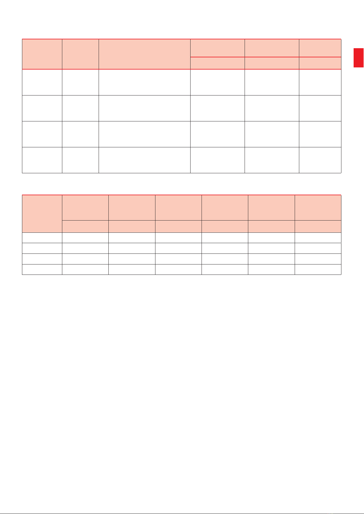
51
Model Berto’s
code Description Voltage Power cable
H07RN-F Frequency
[V] [mm²] [Hz]
E6MB 15040000
ELECTRIC OVEN 6 Trays
7” TOUCH controls
with BOILER and CLEANING
380-415V3N~
220-240V3~
5x2.5 mm²
4x4 mm² 50/60
E6ST 15080000
ELECTRIC OVEN 6 Trays
5” TOUCH controls
with CLEANING
380-415V3N~
220-240V3~
5x2.5 mm²
4x4 mm² 50/60
E10MB 15060000
ELECTRIC OVEN 10 Trays
7” TOUCH controls
with BOILER and CLEANING
380-415V3N~
220-240V3~
5x4 mm²
4x10 mm² 50/60
E10ST 15100000
ELECTRIC OVEN 10 Trays
5” TOUCH controls
with CLEANING
380-415V3N~
220-240V3~
5x4 mm²
4x10 mm² 50/60
Model
Installed
electric
power
Boiler cavity
power Width Depth Height Weight
[kW] [kW] [mm] [mm] [mm] [kg]
E6MB 10 9.6+9.0 895 940 (1000) 860 140
E6ST 10 9.6 895 940 (1000) 860 125
E10MB 18.5 18+9.0 895 940 (1000) 1140 160
E10ST 18.5 18 895 940 (1000) 1140 145
TECHNICAL AND ELECTRICAL DATA TABLE

52
1
2
01
PET
06
PS
PP+PET
CA
FOR
CA
CHECKING AND DISPOSING OF
PACKAGING
1
After unpacking and before moving the appliance to the
installation site, visually check it has not been damaged
during transport. If you notice any damage or anomalies,
do not proceed with the installation and promptly inform
the carrier or manufacturer.
Damaged appliances must not be returned to the
manufacturer without prior notice and without
having obtained prior written authorisation.
DISPOSING OF PACKAGING
area as it could hinder transport to the installation
site and cause a potential risk of entanglement and
must be properly disposed of according to the standards
in force in the country where the appliance is installed. If in
doubt, contact the local authorities for information on how
to dispose of it correctly.
2
below:
• Triple wall cardboard box: Recyclable | material: paper |
marking: PS06
• Pallet: Recyclable | material: wood | marking: FOR
• Polystyrene: Recyclable | material: polystyrene | marking:
PS06
• Cardboard corners and paper sheets: Recyclable | mate-
rial: paper | marking: PS06
• Straps: Non recyclable | material: Polypropylene (PP) and
Polyester (PET)
• Film: Recyclable | material: polyethylene terephthalate |
mark.: PET01
CHECKING COMPONENTS
The packaging must contain the following components
and/or accessories:
• countertop oven;
• instruction manual:
• declaration of conformity;
• warranty certificate.
Contact the manufacturer if anything is missing or
damaged.
generic packaging, depending on the model
visually check for damage
53
3
4
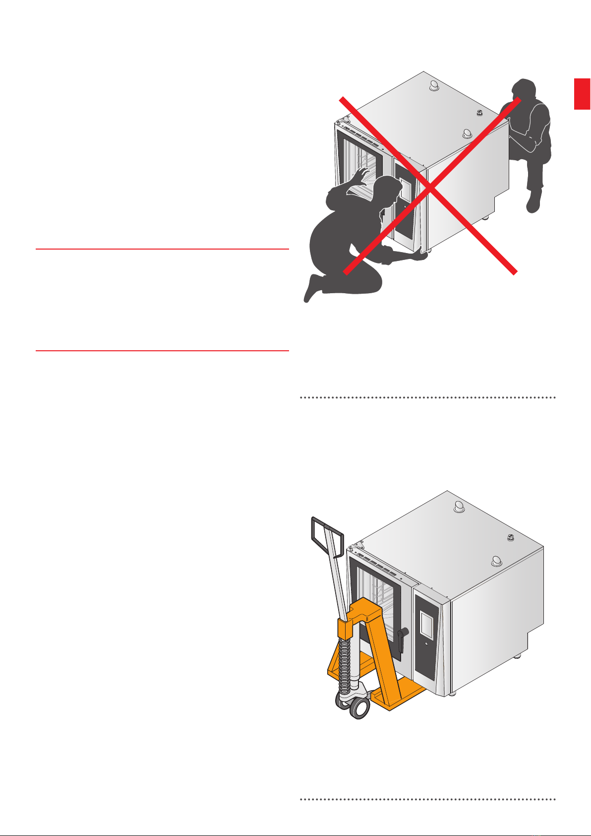
TRANSPORTATION
The appliance must be transported and lifted:
•in full compliance with laws on accident prevention
and the regulations in force and with the utmost care;
• by professionally enabled, authorised and trained per-
sonnel in good physical and mental condition;
•while using PPE (personal protective equipment
;
•while keeping the appliance vertical.
• after making sure there are no people or things in
the manoeuvring area that could get in the way;
• after making sure that the floor is perfectly smooth,
level, even, free of obstacles and not slippery.
3
The appliances must NOT be moved manually, with
straps, or by dragging or pushing them.
The manufacturer shall not be held liable for any
inconvenience caused by transportation carried out in
any other conditions.
4
Insert the prongs at the front or rear using a pallet
jack suited to the weight of the appliance, taking care
not to damage its base.
Lift the appliance enough to move it easily and take
particular care to balance the weight as the centre of
gravity is not in the geometric centre of the appliance.
Take care with tilting during movements; always keep
the appliance vertical.
Lifting equipment (pallet jack, forklift, etc.) must be
suitable for the mass, dimensions and movements to
be carried out; when lifting any part, use a lifting device
with a load capacity at least 20% more than the weight
of the part to be transported.
use makeshift means to attach and lift parts of the
appliance.
these instructions.
incorrect oven transportation
correct oven transportation

54
5
6
Max 35°C/95°F
Min 5°C/41°F
Max 70%
GETTING STARTED
REMOVING THE PROTECTIVE FILMS
5
Clean any glue residue with an appropriate solvent
without using tools, abrasive detergents or acids that
could spoil the surfaces.
the reach of children and animals as they are potentially
dangerous. Dispose of them correctly in compliance with
local regulations.
REMOVING NON-COMPLIANT OBJECTS
Make sure that no non-compliant objects (e.g. bags,
manuals, etc.) are inside the oven cavity.
INSTALLATION ROOM
6
The appliance installation room must:
•have a smooth, perfectly level oor, which can with-
stand the weight of the appliance at full load.
•be sheltered from direct sunlight and the elements (e.g.
rain);
• be ventilated and have proper exchange of air: if
natural ventilation is not possible, forced ventilation may
be used.
•comply with the laws in force on system safety, work-
place safety and re prevention;
• not contain potentially explosive or ammable
materials or substances (e.g. gas cylinders, wooden
partitions, etc.) due to the risk of re and explosion;
• be designed solely for food storage;
• have a temperature between 5 °C and 35 °C;
• be equipped with all the necessary power supply (elec-
tricity, gas, water) and waste disposal connections (e.g.
evacuation of fumes);
• be adequately lit and meet all the hygiene and sanitary
requirements under current law.
installation room
getting started

55
The appliance must not be exposed to vibration, high frequency noise, dust or foreign materials, as such exposure
may cause deterioration or mechanical faults.
It must be easy to move the appliance for any extraordinary maintenance work. Make sure that any masonry work
after installation (e.g. building walls, replacing doors with narrower ones, renovations, etc.) does not obstruct
movement.
THE IMPORTANCE OF PROPER LEVELLING
The appliance is tted with feet that can be turned clockwise or anticlockwise to level it if the oor in the
installation room is not perfectly at.
Incorrect levelling may slow the ow in the drain circuit, resulting in limescale build-up or stagnation.
It may also lead to cooking fat being incorrectly distributed inside the trays with a risk of overow, which is
extremely dangerous during removal.

56
7
8 9
POSITIONING
7
The appliances must be placed solely on a
substructure provided by you or the manufacturer,
The structure must be:
• stable and perfectly level;
• unmoveable;
• heat resistant and not ammable;
• able to support the appliance weight at full load without
deforming or experiencing structural failure.
If using your own structure, for safety reasons we
recommend it not be too high, so that the top tray is
below a height of 160 cm. If this is not possible, the
sticker included in the packaging must be applied at a
height of 160 cm.
8
If using the manufacturer’s structure, fasten the oven to
it using the bracket provided.
9
After positioning the appliance, it must be levelled by
turning the support feet.
oven positioned on the manufacturer’s
substructure and tray tipping sticker
levelling the ovenfastening the oven to the substructure
57
10
11
5 cm
50 cm 50 cm
50 cm
70 cm
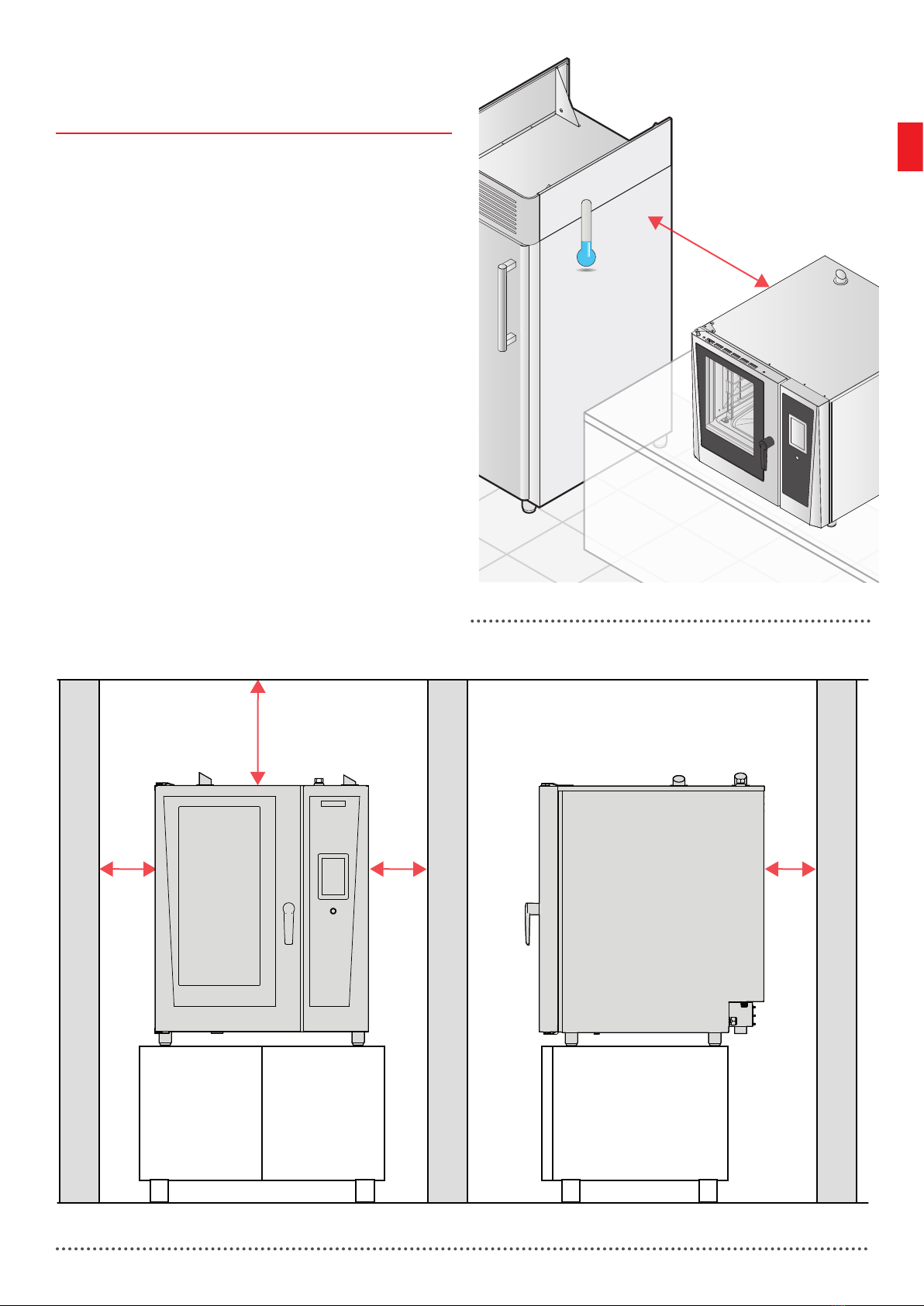
MINIMUM CLEARANCES
10
| 11
Position the appliance:
• so that you have easy access to electrical connections;
• approximately 70 cm from cold appliances (e.g. blast
chillers or refrigerators). If the indicated clearance can-
not be complied with, place an insulating reproof wall
between the two appliances that can withstand tem-
peratures of at least 150°C.
• leaving the clearances indicated in the gure from any
walls or other neutral appliances.
Always make sure that the chosen installation position
allows the door to be opened fully, and daily cleaning
and special maintenance (e.g. repairs) to be carried out.
Also check there are no curtains or other easily
(e.g. gas cylinders) near the appliance.
The appliance is not suitable for recessed
installation.
minimum clearances from other appliances
minimum clearances

58
SECTION INDEX
CONNECTIONS ......................................................... 59
SEE THE RATING PLATE..............................................................................59
ELECTRICAL CONNECTIONS.......................................................................60
PLUMBING CONNECTIONS.........................................................................62
INSTALLING DETERGENT AND RINSE AID TANKS.......................................63
EVACUATION OF FUMES........................................ 64
REPLACING PARTS ................................................. 64
FINAL INSPECTION.................................................. 65
ALARMS TABLE........................................................ 66
Connections and
inspections
59
E6MB
50/60
10
12
13
E6MB
21100/1234Z
E6MB
50/60
10
E6MB
21100/1234Z
E6MB
50/60
10
CONNECTIONS
All connections must be carried out by
qualied technicians authorised by the
manufacturer using personal protective equipment
(PPE) (e.g. gloves, safety footwear) in accordance
with the requirements and standards on systems
and workplace safety in force in the country of use:
failure to follow these instructions may cause damage
and injury, voids the warranty and relieves the
manufacturer of all liability.
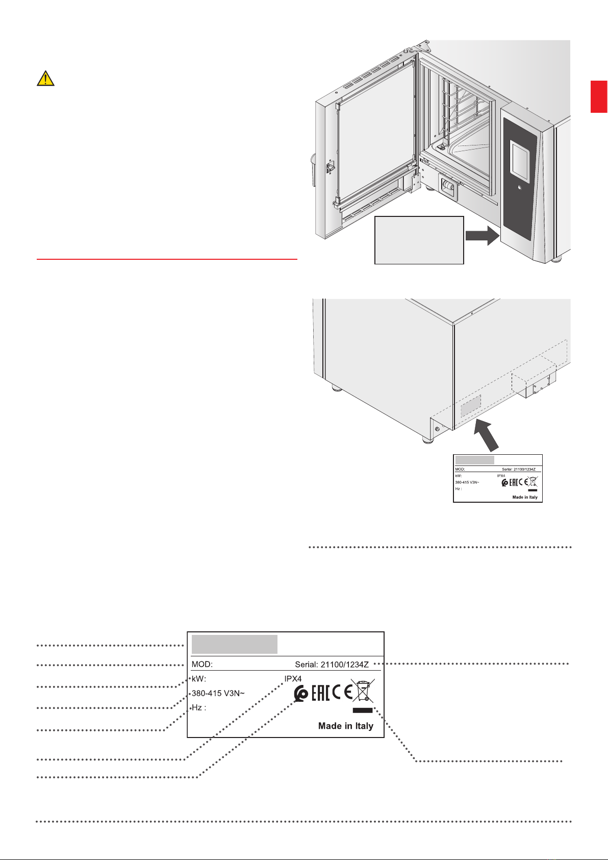
SEE THE RATING PLATE
12
| 13
Before making the connections, check the appliance
data to ensure it matches the system data; all data is
shown on the rating plate found on the back or inside
the door (in basic form).
The rating plate provides important technical
information. This information is essential in case of a
request for maintenance or repair to the appliance. Do
not remove, damage or modify it.
Manufacturer
Oven model Serial number | item number
The symbol indicates that the
product must not be disposed
of with other waste at the end
of its useful life, but must be
collected separately
Oven power
Power supply
Frequency
Protection rating
basic rating plate
full rating plate
reading the rating plate
position of rating plate

60
14
380-415V 3N 50/60Hz
220-240V3 50/60Hz
2
1
3
4
5
7
L3
N
L2
L1
6
ELECTRICAL CONNECTIONS
SAFETY PRECAUTIONS
• Before connecting, carefully read the safety warnings
at the beginning of this manual.
•Do not use adapters or multi sockets for the connec-
tion. Do not splice the power supply cable in any way.
•Do not coil the cable if it is too long and ensure it is not
kinked, pinched or blocking people’s transit.
• There must be an earth connection made using a
single, seamless cable, without interruptions (including
the circuit breaker). The yellow/green earth wire must be
at least 10 mm longer than the other wires.
CONNECTING TO THE ELECTRICITY MAINS
Appliances are supplied without a power supply
cable
a cable with a suitable cross-section and type to the
internal terminal board in accordance with that shown
in the wiring diagrams attached to the appliance. See
Technical and electrical data table page 51 for
information on the cable cross-section and type.
replaced solely by a qualied and authorised
technician. The cable can only be replaced by one with
the same characteristics (H07RN-F).
14
Connection procedure:
12open the right-hand panel;
3... 5loosen the cable gland and insert the power
cable;
6
7tighten the cable gland and close the oven’s
right-hand panel.
electrical power connection
This manual suits for next models
3
Table of contents


