Best.Energy Eniscope Hybrid User manual

ENISCOPE MANUAL [V.1.1]
Hybrid User Manual
[SWITCH ON TO EFFICIENCY]

Note: The word Eniscope
throughout the document
refers to the Eniscope Hybrid.
[ENSCOPE HYBRID MANUAL]
2
Table of Contents
Section 1 Installation 8
Important Safety Notice 8
AMounting the Eniscope 9
B The Auxiliary Supply 10
CElectricity Monitoring 11
i Voltage Sensing Installation 11
ii CT Installation 14
DPulse Monitoring Installation 20
EModbus Communications 22
(RS485 Serial connection)
FTemperature Sensing (3.5mm stereo jack) 23
Section 2 SD Card Port 25
Section 3 USB Ports 25
Section 4 Commissioning 26
A Connecting to the Network 26
B Meter Setup 31
CReal Time Display 33
DActivating the Eniscope Hybrid 34
EResetting the Eniscope Hybrid 35
Section 5 Customisation Options 37
Alarms 37
Messaging 38
Interface Options 39
Security 39
MQTT Settings 40
Renewable Display 43
Section 6 Troubleshooting 44
Support Tab 44
How to nd your Eniscope on the Network 45
Eniscope Direct Communication 49
LED Indication 51
Section 7 Technical Specication 52

Important Safety Information
This manual may not be altered or reproduced
in whole or in part by any means without the
express written consent of Best Energy Saving
Technology Ltd.
The information contained in this document
is believed to be accurate at the time of
publication, however, Best Energy Saving
Technology Ltd assumes no responsibility for any
errors which may appear here and reserves the
right to make changes without notice.
Please read this manual carefully before
installation, operation and maintenance of the
Eniscope meter. The following symbols in this
manual and on the Eniscope meter are used
to provide warning of danger or risk during the
installation and operation of the meters.
Electric Shock Symbol:
Carries information about procedures
which must be followed to reduce
the risk of electric shock and danger
to personal health.
Safety Alert Symbol:
Carries information about
circumstances which if not
considered may result in injury
or death.
Installation and maintenance of the Eniscope
should only be performed by qualified,
competent professionals who have received
training and should have experience with high
voltage and current devices.
Best Energy Saving Technology Ltd shall not be
responsible or liable for any damages caused by
improper installation.
3
[ENSCOPE HYBRID MANUAL]

Manufacturers Declaration of Conformity
This is to certify that the products described in this manual conform to the
requirements of the following standards in respect of the low voltage directive,
2006/95/EC.
IEC/UL/EN61010-1, 3rd Edition
Safety requirements for electrical equipment for measurement, control, and
laboratory use.
The products described in this manual conform to the requirements in respect of the
EuropeanEMC directive, EN61326-1:2013.
Electrical equipment for measurement, control, and laboratory use.
Signed:
Troy Wrigley, CEO
Best.Energy
Southview House
St Austell Enterprise Park
Carclaze
St Austell
PL25 4EJ
[ENSCOPE HYBRID MANUAL]
4

Considerations When Installing
the Eniscope Hybrid
Installation of the Eniscope must be performed
by qualified personnel only, who follow standard
safety precautions through the installation
procedures. Those personnel should have
appropriate training and experience of high
voltage devices. Appropriate safety gloves,
safety glasses and protective clothing are highly
recommended.
During normal operation, dangerous voltage may
appear on many parts of the Eniscope, including
terminals, CT’s (Current Transformers), PT’s
(Potential Transformers) and I/O (Inputs and
Outputs) modules. All primary and secondary
circuits can produce lethal voltages and currents.
AVOID contact with any current-carrying surfaces.
The Eniscope and its I/O output channels are NOT
designed as primary protection devices and shall
NOT be used as primary circuit protection or in an
energy-limiting capacity. The Eniscope and its I/O
output channels can only be used as secondary
protection. AVOID using under situations where
failure of the Eniscope may cause injury or death.
AVOID using the Eniscope for any application
where risk of fire may occur.
All terminals should be inaccessible aer
installation. All wiring to auxiliary supply, voltage
sensing inputs, CT inputs and any conduction
paths must be inaccessible aer installation.
This should be achieved by enclosing the wiring
in conduit, or by installing the entire unit in an
inaccessible enclosure.
Do NOT perform Dielectric (HIPOT) test to any
inputs, outputs or communication terminals.
High voltage testing may damage electronic
components of the Eniscope.
Applying more than the maximum voltage to the
Eniscope and/or its modules will permanently
damage the Eniscope and/or its modules. Please
refer to the specifications for all devices before
applying voltages.
IMPORTANT
Note: if the equipment is used
in a manner not specied by the
Manufacturer, the protection provided
by the equipment may be impaired.
Note: There are no serviceable parts
within the equipment. The equipment
must be returned to the manufacturer
for servicing.
5
[ENSCOPE HYBRID MANUAL]

[ENSCOPE HYBRID MANUAL]
6
Eniscope Hybrid is a multi-channel, three
phase energy meter and sensing system
combined with a processing facility designed to
gather, summarize, store and transmit energy
related information to Web based servers for
presentation and analysis.
The Eniscope oers the world’s first truly
integrated ecosystem for energy monitoring and
eiciency, identifying waste and eliminating costs.
The best in class energy metering system
combines up to 8 three-phase metering points
and up to 8 pulse inputs, which can be arranged to
monitor total gas and water consumption.
The compact, plug and play system can be easily
installed by an electrician, instantly providing real-
time data on energy consumption patterns by
individual piece of equipment, circuit, building or
property portfolio.
For those generating their own power, the
Eniscope records minute-by-minute data.
Information can be displayed to building
occupants, or included on websites, via an
attractive range of public displays.
Data can be viewed in real-time on any
computer, or across a range of portable devices
from anywhere in the world. Historical data
can be accessed and analysed, at one-minute
resolution via the Best.Energy Analytics system.
The Eniscope has been engineered to allow
continuous, remote improvements and upgrades
via the cloud, making this the world’s most
durable and future proof solution to energy
monitoring and eiciency.
Contact your Best.Energy Distributor today to
learn how your organisation can benefit from
advanced real-time energy management.
Eniscope Hybrid Description
7
[ENSCOPE HYBRID MANUAL]
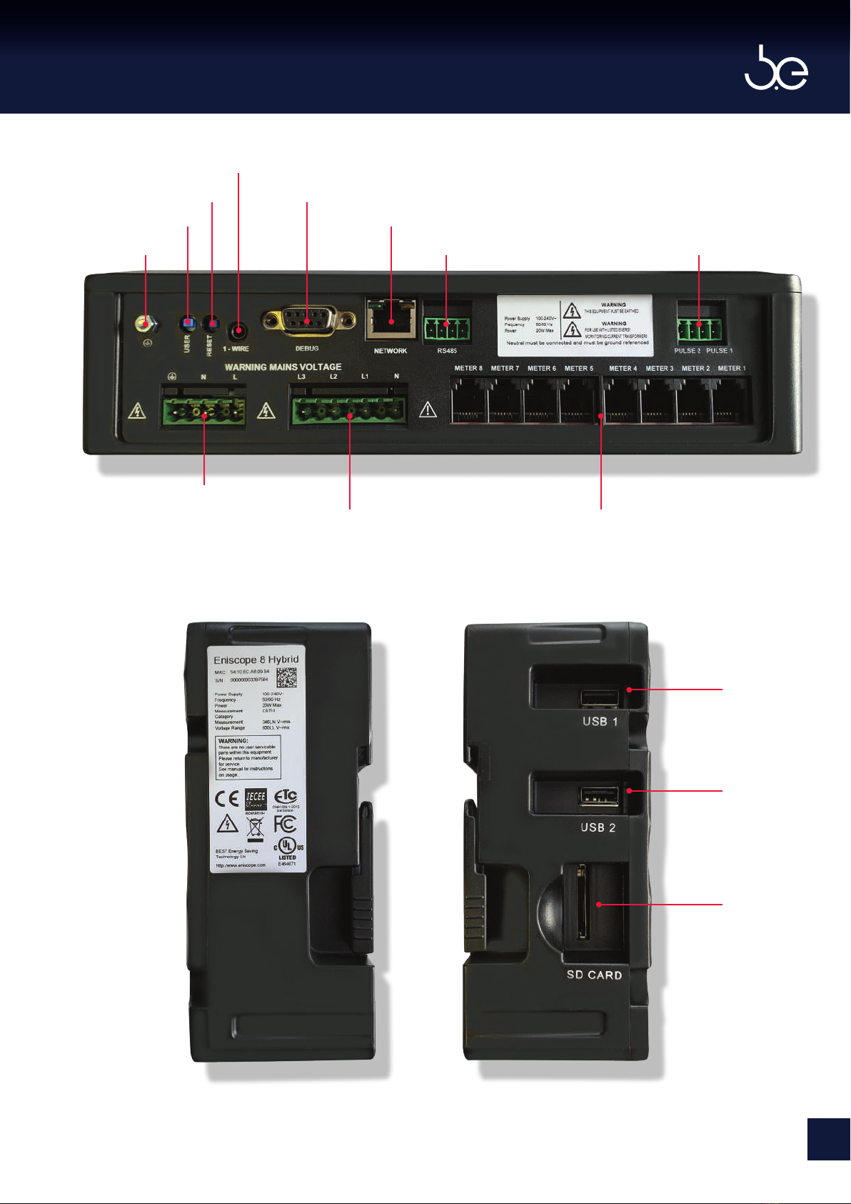
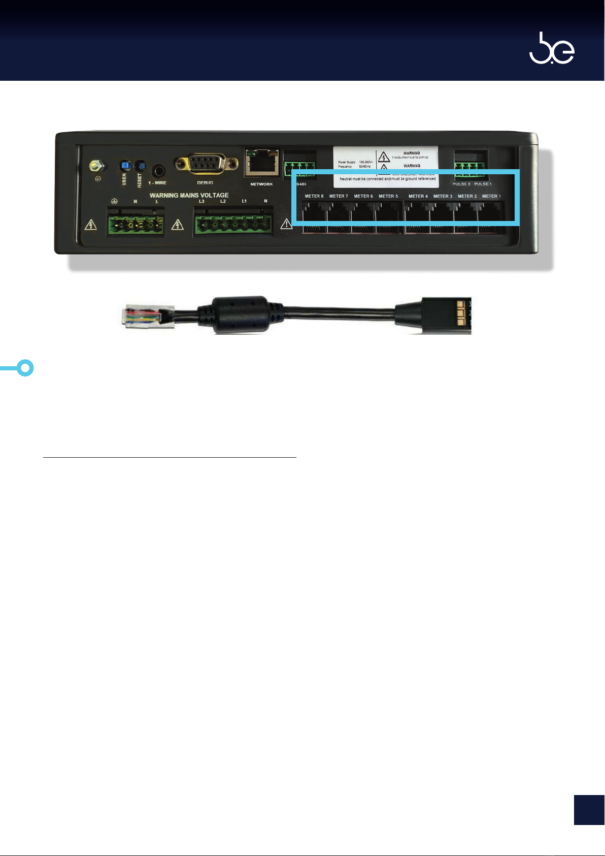
Eniscope Hybrid Identication
One Wire Temperature Input
Reset Button 9 Pin Serial Connection
Network Connection RJ45User Dened Push Button
Enclosure Ground
Aux Power Supply
3 Phase Voltage Reference 3 Phase CT Inputs x4 or 8
USB Port
USB Port
SD Card
Modus Pulse Inputs Meter 1 & 2

[SECTION 1]
INSTALLATION
Please follow the ‘First Installation
Guide’ under ‘Eniscope > Eniscope
Hybrid (2018)’ headings at the
support desk, for full guide before
any installation.
http://help.bestsupportdesk.com/
[ENSCOPE HYBRID MANUAL]
8
SAFETY AT WORK
The owner, installer and user of this Eniscope
measurement device are responsible for its correct
installation and use, and must ensure that;
A Only qualified persons install the unit.
BIsolate AC equipment before installation.
CThe installation complies with the information
contained in this publication.
DAll units must be installed in accordance with the
current National Electrical Code.
Best.Energy or their agents do not assume any liability,
expressed or implied, for any consequences resulting
from inappropriate, negligent or incorrect installation,
application, use or adjustment of this device.
Environmental
There are no specific ventilation requirements
however, please check the environment,
temperature and humidity to ensure the Eniscope
is within the correct operating conditions. Also
before you begin to mount the Eniscope ensure
that there is nothing that will hinder or restrict the
multiple ports on the bottom and le hand side.
The Eniscope is Type 1, for indoor use only.
The Eniscope is designed to be mounted on a
vertical surface within an electrical cabinet or
wall mount, using the Eniscope Gland Box or
suitably mounted trunking for incoming cables.
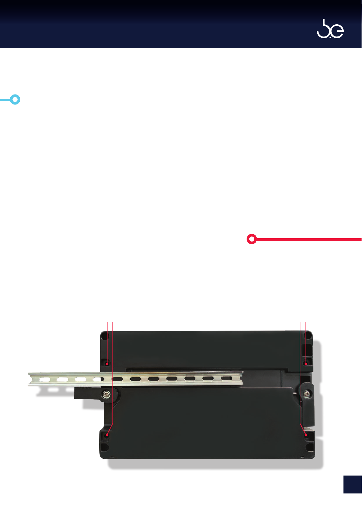
Eniscope can be mounted using the corner
mounting holes or the mini din rail provided.
There is a mounting hole template provided for
both the Eniscope and the Gland Box.
A Mounting the Eniscope
Additional Mounting Holes
Mini Din Rail
Additional Mounting Holes
Dimensions:
Height 144mm
Width 236mm
Depth 60mm
Weight 0.80kg
9
[ENSCOPE HYBRID MANUAL]
The Eniscope requires an Aux power supply to
energise the processor and metering elements.
The typical power consumption is very low (20W)
and can be supplied by an independent source
(or by the measured voltage line). A regulator or
an uninterrupted power supply (UPS) must be
used under high voltage fluctuation conditions or
frequent power failures (1 per day).
Please ensure an Isolator (disconnect) switch is
installed no more than 1 meter from the Eniscope
and within easy reach of the operator, and shall
be clearly labelled as the disconnecting/isolating
device for the equipment. A suitably rated MCB
supply must be included in the installation.
Aux supply requirements:
• 100 to 240 V~ Nominal, Over Voltage
Category II
• 50 /60 Hz Nominal
• 6 amp double pole MCB ‘B’ trip curve to
IEC 60898 should be used on the auxiliary
supply. A similar specified RCD/ELCB device
can also be used.
• Alternatively 6 amp medium time delay
fuses can be used.
B The Auxiliary Supply
Cable Requirements
• Conductor AWG:18 AWG, NFPA70
“National Electrical Code”
• Voltage Rating: 600 V~
• Conductor Area CSA: 1 mm2 Min
• Conductor Material: Copper
• Operating Temperature -20°C to +105°C
• Flame Rating VW-1
Note: 100 to 240 V~ Nominal. This is
lower than can be sensed, be sure the
maximum 260V is not exceeded.
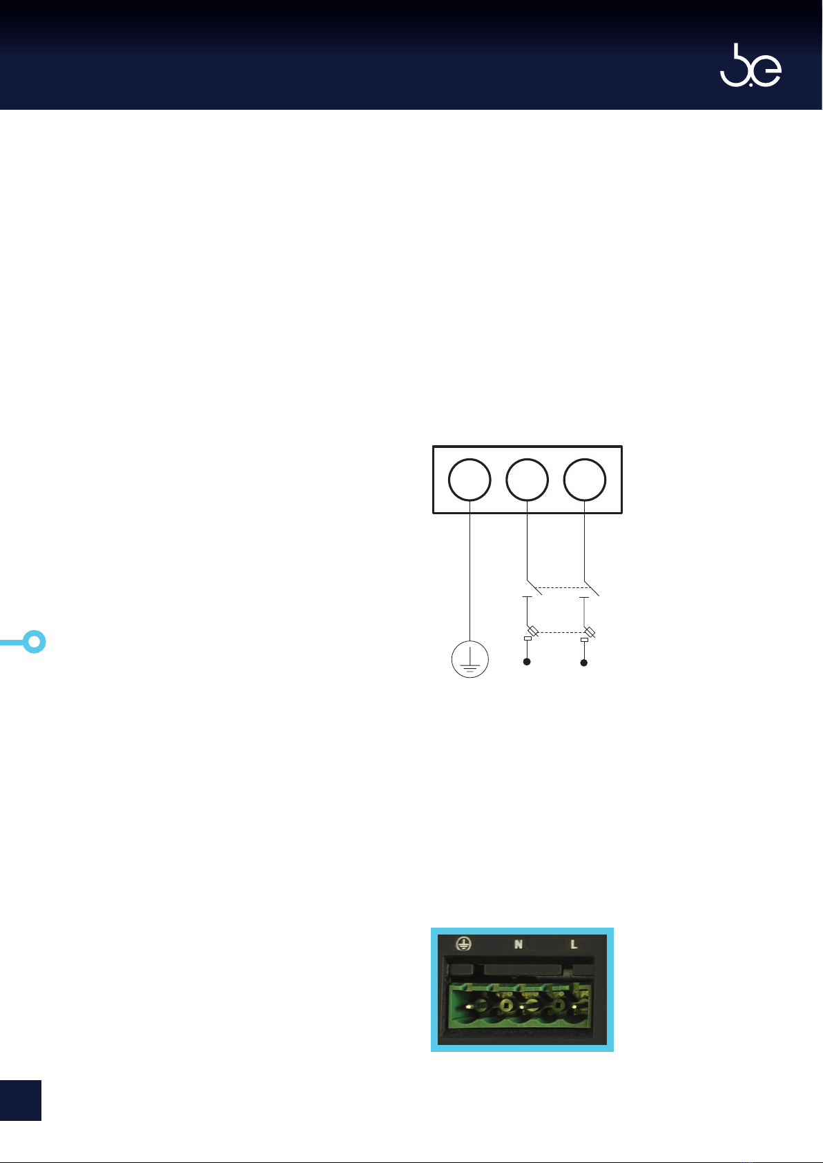
Instructions: Connect the AUX supply
to the Eniscope, as shown in the
wiring diagram.
E N L
6 amp MCB
Isolator
Switch
[ENSCOPE HYBRID MANUAL]
10
To provide all of the required electrical
parameters, the Eniscope Hybrid needs to monitor
your Voltage and Current supply. This section
should be closely followed and the previous safety
page should be read before proceeding.
Voltage Input
Maximum sensing input voltage for the Eniscope
Meter shall not exceed 346LN/600LL V~ rms for
three phase or 346LN V~ rms for single phase.
A Neutral must be connected and should be
ground referenced (PME). There shouldn’t be a
voltage dierence between Neutral and Earth.
Cable Requirements
• Conductor AWG: 18 AWG, NFPA70
“ National Electrical Code“
• Voltage Rating: 600 V~
• Conductor Area CSA: 1 mm2
• Conductor Material: Copper
• Operating Temperature -20°C to +105°C
• Flame Rating VW-1
6 amp MCB
A 6 amp triple pole MCB ‘’B’ trip curve to
IE C 60898 should be used on the voltage
measurement input terminals. A similar specified
RCD/ELCB device can also be used.
C Electricity Monitoring
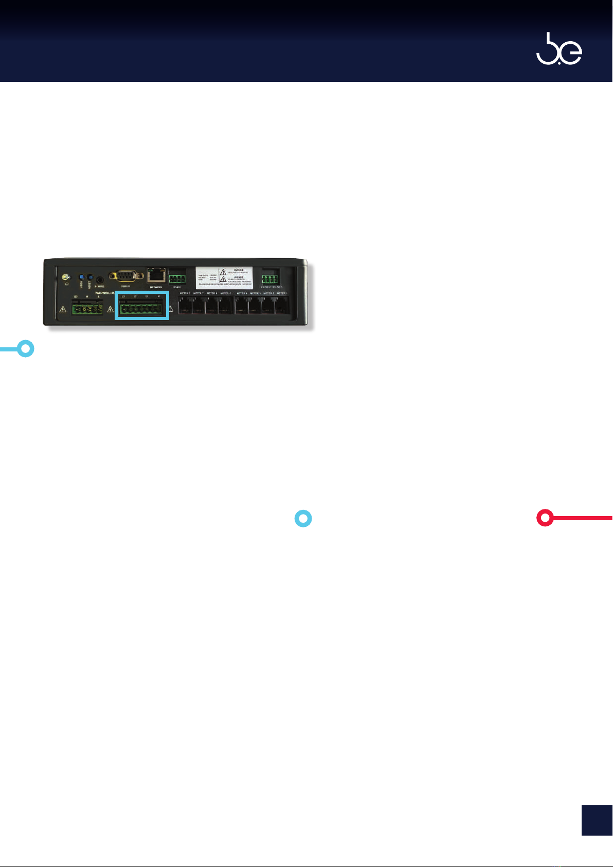
i) Voltage Sensing Installation
Instructions
1. Identify a Distribution board that
can supply a three phase (or
Single) reference supply via a MCB.
2. Remove the protective cover
to expose the Voltage sensing
connections on the Eniscope.
3. Connect the voltage reference
cables to the connectors using
the correct wiring conguration,
as shown on next page (Single
Phase, Single Phase Two Wire or
Three phase).
Isolator – Disconnect Switch
A 16 amp four-pole Isolator/Disconnect
switch rated at a minimum of 600V~ must be
included in the installation. The switch needs
to be in close proximity to the equipment and
within easy reach of the operator. The switch
must be marked as the disconnecting device
for the equipment.
11
[ENSCOPE HYBRID MANUAL]

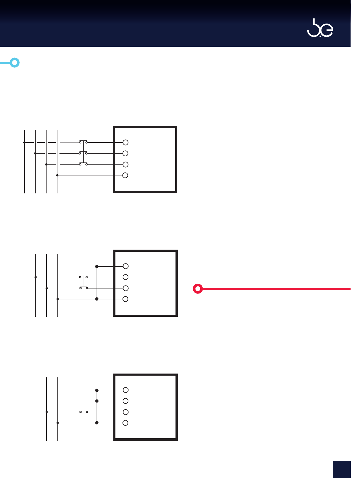
Neutral Generator
For Eniscope to function correctly a neutral
conductor needs to be connected to the voltage
sensing circuit on the Eniscope. In some territories,
primarily the United States of America, some
supply systems for historical reasons have no
neutral conductor. See Figures 1, 2, 3, 4 and 5
below. In order for Eniscope to measure such
systems we must create a neutral reference
conductor using the Best.Energy supplied neutral
generator.
Best.Energy Neutral Generator
In territories where no neutral is available
Best.Energy can supply a neutral generator
module which ban be mounted inside the
Best.Energy supplied gland box or within the
same enclosure as the Eniscope. Contact
Best.Energy for installation and wiring details.
Note: In Delta system ensure,
Neutral-line voltage does not exceed
the maximum voltage limit.
For Star or Wye connection
with the star point grounded.
L1
L2
L3
Figure 1
L1
L2
N
N
NN
N
L3
Tee connection with phase
mid point grounded.
Figure 2
Delta connection with phase mid
point grounded. (High Leg Delta)
Figure 3
L1
L2
L3
Open Delta connection with
phasemid pointgrounded.
Figure 4
L1
L2
L3
N
Transformer connection with the star point
connected to Eniscope.
L1
L2
L3
Figure 5
TX2
TX1
TX3
Delta connection with one
phase grounded. (Corner Delta)
Figure 5
L1
L2
L3
[ENSCOPE HYBRID MANUAL]
12
Voltage Sensing Congurations
Note: Multiple Single Phase
Circuit Monitoring (2-Line Only)
On 2-Line systems, up to 3 CTs
can be tted to one Eniscope
3-phase CT Input connector.
Potentially allowing you to
monitor up to twenty four 2-Line
Single Phase Inputs.
For this conguration L2 and L3
must be connected to L1 instead
of LN (to be given a voltage
reference).
L3
L2
L1
LN
L3 L2 L1 N
LINE
6 amp MCB
L3
L2
L1
L
N
L2 L1 N
6 amp MCB
L3
L2
L1
L
N
L1 N
6 amp MCB
Single Phase Connection (2LN)
3-Line (mainly used North America)
Single Phase Connection (LN)
2-Line
Three Phase Connection (3LN)
3-Phase 4-Line (Most common connection)
LINE
LINE
LOAD
LOAD
LOAD
13
[ENSCOPE HYBRID MANUAL]

Current Transformer Installation
Overview
A current transformer (CT) produces a voltage
output signal directly proportional to the current
flowing in the conductor around which it is
positioned. The output signal from the CT is sent
to the meter and the current flow in the primary
circuit calculated. A CT is required for each phase.
• Only CT’s listed by the manufacturer should
be used. Under NO CIRCUMSTANCES use any
other type of CT as severe damage or injury
may result.
• Current transformers are marked with the
ratio between the maximum primary current
and the maximum secondary signal. For
example a 200 A:333 mV CT produces a 333
mV output signal when the maximum rated
200 A is flowing through the primary.
• It is best to match the CT primary as closely
as possible to the maximum expected
current to get the best accuracy. This is
because CT’s are less accurate at low loads
than they are at full load.
• If using a 200 A CT you will need to input a
figure of 200 into the Eniscope meter
settings menu. Information on how to
complete this, can be found in the
commissioning section, under meter setup.
CElectricity Monitoring
ii CT Installation
Polarity
• CT’s are direction sensitive and must
be fitted the correct way around. CT’s are
marked with an arrow on the body to
indicate which direction they should face
around the cable or buss-bar. The arrow
must point towards the load or in the
direction of normal power flow.
• The CT outputs must be connected to the
meter the correct way round, otherwise
the meter will not register correctly (i.e.
negative readings). Current transformers
are supplied with secondary leads black
and white in colour which must be
connected to the correct terminals on
RJ12 adaptor.
• The CT’s must be connected to the correct
phase inputs on the meter. The meter
will not register correctly if the CT for L1
is connected to the inputs for L3 current,
for example.
• Unused CT inputs should be shorted
together to avoid spurious readings.
Please follow the instructions on the next pages for a successful installation
[ENSCOPE HYBRID MANUAL]
14
Caution, risk of electric shock
Ignoring this warning can lead to
serious injury or death.
Only listed CT types should be used with the
equipment. Failure to adhere to this requirement
will invalidate the warranty.
Please check the Support Desk Current
Transformers section, regarding range of
available CT sizes and ratings:
http://help.bestsupportdesk.com
At the time of printing, the CT range includes:
25mm Aperture 30 Amp
CT/BCF30/30A/25
25mm Aperture 60 Amp
CT/BCF60/60A/25
25mm Aperture 120 Amp
CT/BCF120/120A/25
25mm Aperture 300 Amp
CT/BCF300/300A/25
50 x 50mm Aperture 500 Amp
BCT/4LSF500A/50/50
50 x 88mm Aperture 1000 Amp
BCT/4LSF1000A/50/88
63 x 100mm Aperture 2000 Amp
BCT/4LSF2000A/63/100
63 x 138mm Aperture 3000 Amp
BCT/4LSF3000A/63/138
75 x 175mm Aperture 4000 Amp
BCT/4LSF4000A/75/175
75 x 225mm Aperture 6000 Amp
BCT/4LSF6000A/75/225
Important Safety Information
15
[ENSCOPE HYBRID MANUAL]

Important Safety Information
Warning
Read all documentation prior to service or
installation
Important: Must be certified to UL2808, XOBA
for field installation.
Only to be installed in a ambient temperatures
between -40C and +55C. Maximum altitude 2000
meters.
1. The recommended current transformer
types are intended for field installation
within distribution and control equipment
to measure electrical current.
2. Always disconnect the circuit from the
power distribution system before service
or installation.
3. Do not install the current transformers in
an area blocking ventilation or in an area
of breaker arc venting.
4. These current transformers are not suit
able for Class II wiring methods or
connecting to Class II equipment.
5. Do not allow the current transformer or
cables to come into direct contact with
live terminals or buss that exceeds
voltages of 600V~.
6. The CT may not be installed in equipment
where they exceed 75% of the wiring
space of any cross-sectional area within
the equipment.
Installation Instructions for
Current Transformers
Important Safety
Information
Caution, risk of
electric shock
[ENSCOPE HYBRID MANUAL]
16

Method of Installation
1. Locate and isolate power to distribution panel
where installation is to take place.
2. Identify the single conductor wire to be
monitored and direction of flow/load.
3. Attach the current transformer around
the conductor to be monitored without placing
excessive strain or pressure. Do not route the
leads over sharp edges and take care to fit the
CT with the arrow in direction of flow/load.
Notes: If you placed the wire in the
wrong terminal, gently press plastic
clip with a screwdriver to release
(as seen in picture above).
If the Analytics platform shows a
negative kW trace, either reverse the
black and white leads or reverse the
direction of current ow through the
CT’s.
4. For greater accuracy of measurement it is
advisable to cable tie the conductor to the
CT body so the conductor passes through
the centre of the CT.
5. Repeat steps 2 to 4 for the other phases to
be measured.
6. Now push the CT secondary leads into the
RJ12 adaptor terminals for your phase
type as shown on the next page. The white
cable of each CT connects to either
terminals 1, 2 and 3 of the side showing the
Best.Energy logo. The corresponding black
cable of each CT connects to terminal of
same number on the opposite side of the
terminal block.
17
[ENSCOPE HYBRID MANUAL]

LINE
LOAD
L3 L2 L1 N
Three Phase
Two Phase
Single Phase
White
Black
White
Black
White
Black
3 3
2 2
1 1
RJ12 Connector
White
Black
LINE
LOAD
L2 L1 N
White
Black
1 1
2 2
3 3
RJ12 Connector
LINE
LOAD
L1 N
White
Black1 1
2 2
3 3
RJ12 Connector
Logo Side Logo Side Logo Side
Note: Multiple Single Phase
Circuit Monitoring (2-Line Only).
On 2-Line systems, up to 3 CTs can be
fitted to one Eniscope 3-phase CT Input
connector. Potentially allowing you to
monitor up to twenty four 2-Line Single
Phase Inputs.
For this configuration, fit the second
CT to terminals 2 and the third CT to
terminals 3 and in meter setup select
3 phase type.
[ENSCOPE HYBRID MANUAL]
18
Method of Installation
7. Once all the required CT’s have been
connected to the RJ12 adaptor, plug the RJ12
into the correct CT point on the Eniscope.
8. You can now turn the power on to the
distribution panel.
Notes: If you need to extend the CT lead
this can be done up to 10 meters using a
600V 1mm2 18 AWG, single core wire to
VW-1 fame rating. Route CT cables away
from mains voltage current carrying
cables.
You have now completed the Electricity
monitoring section. Please review the
commissioning section to ensure the Real-time
display and Analytics is receiving the recorded
data.
19
[ENSCOPE HYBRID MANUAL]

The pulse inputs are designed to interface the
pulse outputs of existing mechanical gas and
water meters to the Eniscope. These types of
pulse outputs are usually mechanically generated
using switches that periodically connect the two
contacts together. They are commonly called
‘dry’ contacts as they do not have any voltage or
current on them.
Only non-powered circuits should be connected.
Typical input would be from the reed-relay switch
(pulse output) of a water meter conforming to
IEC62053-31 or DIN43864 (S0).
So that the Eniscope can ‘read’ the pulse it
supplies a very small, current limited, to the pulse
input, and via the wiring to the pulse output of
the water/gas meter. This is called ‘wetting’ the
contacts. When the ‘pulse’ is present, this voltage
is ‘sunk’ by pulse source. To prevent ‘contact
bounce’ and hence multiple spurious counts, short
pulses are ignored.
Operating Parameters
Typical open circuit voltage 4.6 V
Typical short circuit current 1.1 mA
To register a pulse the following must be met
during the pulse:
• Maximum short circuit resistance 3k ohms •
• Minimum pulse duration 100 ms
• Maximum pulse duration indefinite
• Max distance 100m
D Pulse Inputs
Notes: The Modbus and Pulse inputs
share a common oating isolated
5V bias supply. If required by local
regulation, they can be connected to
local ground via the common pins on
the Modbus connectors. The isolation
provided is for ground loop breaking
only. Do not assume elevated voltage
isolation.
Important
1. Pulse inputs must only be connected
to galvanically isolated, voltage free pulse
outputs.
2. All pulse inputs (and the modbus) share a
common 0V connection and a common
5V bias supply. The supply is isolated from
ground/earth and all other inputs. Be
careful when connecting to multiple pulse
sources from multiple locations. Additional
protection or isolation may be required by
some Authorities - please consult a
competent local expert.
3. To ensure reliable operation over long
wired connections and in noisy
environments, the short circuit resistance
should be as low as possible and ideally less
than 100 ohms.
4. For pulse outputs that are polarity sensitive
(eg open collector pulse sources), the le
hand input is positive and the right hand
input negative. Please note the minimum
pulse duration.
[ENSCOPE HYBRID MANUAL]
20
Table of contents
Popular Measuring Instrument manuals by other brands


Mitchell Golf
Mitchell Golf DigiFlex Frequency Meter 2.0 user manual

BEKA
BEKA BA304SG quick start guide

DPS Telecom
DPS Telecom NetGuardian Techno Knowledge Paper

Kestrel
Kestrel 5000AG user guide

Audio Precision
Audio Precision AUX-0025 user manual

Helmer Scientific
Helmer Scientific RA1 Operation and service manual


