Accurate Technology ProPanel Classic User manual

ProPanel
Classic
PROPANEL SERIAL # ____________
OPERATION

P/N 800-1090-104 Rev L102012 Page 2 of 44
PRE-CONFIGURED PARAMETERS FOR THIS PROPANEL
SERIAL #
PARAMETER 2 (Reading Direction) 1
PARAMETER 11 (Displayed Units) 2
PARAMETER 13 (Linear Multiplier)
PARAMETER 14 (ProScale Technology) 0
PARAMETER 30 (Offset Addition Enable) 3
PARAMETER 31 (Offset Addition 1) 1.000in
PARAMETER 32 (Offset Addition 1) 1.500in
PARAMETER 33 (Offset Addition 1) .750in

ProPanel Classic Page 3 of 44
WARRANTY
Accurate Technology, Inc. warrants the ProScale Systems against defective
parts and workmanship for 1 year commencing from the date of original
purchase. Upon notification of a defect, Accurate Technology, Inc, shall have
the option to repair or replace any defective part. Such services shall be the
customer's sole and exclusive remedy. Expenses incidental to repair,
maintenance, or replacement under warranty, including those for labor and
material, shall be borne by Accurate Technology, Inc. (Including freight or
transportation charges during the first 30 days).
Except as expressly provided in this warranty, Accurate Technology, Inc.
does not make any warranties with respect to the product, either expressed or
implied, including implied warranties of merchantability or fitness for a
particular purpose, except as expressly provided in this agreement.
Accurate Technology, Inc. shall not be liable for any special, incidental, or
consequential damages or for loss, damage or expense directly or indirectly
arising from the customer's use of or inability to use the equipment either
separately or in combination with other equipment, or for personal injury or
loss or destruction of other property, or from any other cause.
To request repair work, (either warranty qualified parts or not) contact
Accurate Technology, Inc. directly by phone, fax, or e-mail. A Returned
Merchandise Authorization (RMA) number is required before returning a
product for repair.
P/N 800-1090-104 Rev L102012 Copyright © 2012, Accurate Technology, Inc. All rights reserved

P/N 800-1090-104 Rev L102012 Page 4 of 44
Table of Contents
SECTION 1 GENERAL INFORMATION.............................................................6
INTRODUCTION.............................................................................................................6
SPECIFICATIONS1.........................................................................................................7
SECTION 2 PROPANEL OPERATION ..............................................................8
INITIAL SET-UP.............................................................................................................8
CALIBRATION ...............................................................................................................9
OUTSIDE MEASURING:..................................................................................................9
INSIDE MEASURING ......................................................................................................9
CORNER-TO-CORNER MEASURING:.............................................................................10
HOLE-TO-HOLE MEASURING.......................................................................................10
EDGE-TO-HOLE MEASURING.......................................................................................10
GENERAL MAINTENANCE.............................................................................................11
BATTERY REPLACEMENT.............................................................................................11
SECTION 3 READOUT OPERATION ................................................................12
KEY TIMING ...............................................................................................................12
KEYS ........................................................................................................................13
On/Off Key ..........................................................................................................13
Units Key.............................................................................................................13
Plus (+) & Minus (–) Keys....................................................................................14
Datum Key ..........................................................................................................14
FUNDAMENTAL READOUT FUNCTIONS ..........................................................................15
Auto on/off...........................................................................................................15
Reading Direction................................................................................................15
Resolution...........................................................................................................15
Measurement Units.............................................................................................16
Key Lock .............................................................................................................16
Linear Scaling......................................................................................................17
Upper/Lower Limits .............................................................................................17
ADVANCED READOUT FUNCTIONS................................................................................18
Absolute / Incremental.........................................................................................18
Absolute (ABS)................................................................................................18
Incremental (INC)............................................................................................18
Send....................................................................................................................19
Offset Addition.....................................................................................................19
Input/Output Connections....................................................................................20
ADVANCED PROGRAMMING FUNCTIONS........................................................................23
Monitor................................................................................................................23
Hold.....................................................................................................................24
Delete..................................................................................................................24
Go/NoGo.............................................................................................................25
Measurement Accumulator .................................................................................26
Statistics..............................................................................................................27
Compensation.....................................................................................................29
Circuit Board Jumpers.........................................................................................30
SECTION 4 PROGRAMMING ............................................................................31
ProPanel Classic Page 5 of 44
Key Timing ..........................................................................................................31
Resetting All Parameters.....................................................................................31
Enter Programming Mode ...................................................................................32
Navigating Programming Mode:..........................................................................32
Exit Programming Mode......................................................................................33
Pr1 –Datum Key.............................................................................................34
Pr 2 –Direction of Travel.................................................................................34
Pr3 –Key Lockout...........................................................................................34
Pr4 –Display Resolution.................................................................................35
Pr5 –Movement to Wake Readout .................................................................35
Pr6-10 NOT USED..........................................................................................35
Pr11 –Displayed Measurement Units.............................................................35
Pr12 –Readout Auto-Off Time........................................................................36
Pr13 –Linear Compensation...........................................................................36
Pr14 –ProScale Compatibility.........................................................................36
Pr15-Pr21 NOT USED ....................................................................................36
Pr22 –ABS/INC Key Operation.......................................................................36
Pr23 –Auxiliary Keypad Enable......................................................................36
Pr24 –Special Functions ................................................................................37
Pr25 –Special Function Variable....................................................................37
Pr26 –Drift Tolerance.....................................................................................37
Pr27 –Upper/Lower Limits..............................................................................37
Pr28 –Lower Limit ..........................................................................................37
Pr29 –Upper Limit ..........................................................................................37
Pr30 –Offset Addition.....................................................................................38
Pr31 –Offset 1................................................................................................38
Pr32 –Offset 2................................................................................................38
Pr33 –Offset 3................................................................................................38
Pr34 –Offset 4................................................................................................38
Pr35 –External Key Input 1.............................................................................39
Pr36 –External Key Input 2.............................................................................39
Pr37 –Programmable Output Polarity.............................................................39
Pr38 –Programmable Output Function...........................................................39
SECTION 5 MISCELLANEOUS .........................................................................40
FREQUENTLY ASKED QUESTIONS.................................................................................40
DATA TRANSMISSION..................................................................................................41

P/N 800-1090-104 Rev L102012 Page 6 of 44
SECTION 1 GENERAL INFORMATION
Introduction
This manual includes operation and programming information for
ProPanel Classic systems using a ProScale General Purpose Readout with
operating firmware (F/W) of 3.1xxC and higher.
(The Firmware version is displayed on power-up, i.e. P3.100)
ProPanel™ is a general purpose portable measuring tool. It is ideal for
making inside, outside and corner-corner dimensional measurements up to 48
inches (1.2m). In addition, hole-edge and hole-hole measurements are
possible with the optional 3 piece Cone Set.
ProPanel has been designed using high quality extruded aluminum and
machined parts to provide the best accuracy and repeatability.
The measurement technology of the ProPanel Classic is a ProScale®Model
280 Inductive Technology Digital Measuring System.
Optional ‘Cone Set’ used to make
Hole-Hole and Hole-Edge measurements

ProPanel Classic Page 7 of 44
Specifications1
Measuring Range: 48 Inches (1.2m)
Accuracy2:± .015in (±.4mm)
Resolution:.1inch .1mm .1cm or
.01inch .01mm .01cm or
.001inch .01mm .001cm or
.0005inch .01mm .001cm or
1/16inch 1/32inch 1/64 inch
Repeatability: .001in or .01mm or .001cm
Display Range: ± 999.999 in; ± 399 63/64 in
± 9999.99 mm; ± 999.999 cm
Operating Temp: 32 to 120
F 0 to 51
C
Temp Coefficient: 13ppm/
F 25ppm/°C
Max. Slew Rate: 60 inches/sec. (1500mm/sec)
Power: 1 CR123 3V Lithium battery
(or equivalent)
Output Format: Mitutoyo Digimatic® SPC
1Specifications based onProPanel Classic used with a General Purpose LCD
Readout pictured below.
2Maximum observed error over the entire measuring range.

P/N 800-1090-104 Rev L102012 Page 8 of 44
SECTION 2 PROPANEL OPERATION
Initial Set-up
In most instances the initial parameters such as a reference point, measurement units
and resolution will be factory set for your ProPanel System. SEE PAGE 2.
Measurement Units: The measurement units that are displayed (inch, mm, cm) are
selected with the UNITS Key.
Current Position: The Readout allows the current position to be easily configured,
using the +, - and (optionally) DATUM Key.
Reference Point: The Readout allows a reference point (zero or other value) to be
easily recalled using the DATUM Key. The value of this reference point is
programmed at Programming Parameter Pr1..
Reading Direction: The direction, of the reading as the measurement system is moved
is programmed using Programming Parameter Pr2.
Resolution: The resolution of the displayed units is programmed using Programming
Parameter Pr4.

ProPanel Classic Page 9 of 44
Calibration
The accuracy of the ProPanel Classic is dependent on the manufacturing of
the ProScale Measuring System. There are no calibration adjustments
available or necessary.
The Readout has a programmable scaling factor that allows correction for
slight linear inaccuracies. This scaling factor has been pre-set for THIS
ProPanel at the time of manufacturing. SEE PAGE 2.
Also Refer to Section 3: linear scaling
Zeroing the ProPanel is as simple as closing the two jaws and pressing the
DATUM key. Once done, lock the display if desired. This prevents accidental
re-zeroing or setting of any offsets into the Readout. For additional
information, refer to Section 3: DATUM KEY and KEY LOCK
Outside Measuring:
Using the ProPanel like a hand held caliper or T-square, close the jaws
against the edge(s) of the item being measured, and read the result on the
Readout.
Note: Whenever possible, use the full width of the jaw for measurements.
This ensures the most consistent and accurate measurements.
Inside Measuring
Push the F1 key on the Readout. A “1” appears in the upper
left portion of the LCD. This indicates the user programmed
value for Offset Addition 1 (Programming Parameter Pr31), will
be automatically applied to any measurement taken.
Using the upper or lower tips of the ProPanel jaws, measure the inside
dimension of interest and read the result on the ProPanel Readout.
The following measurements use the offset addition function of the ProPanel
Readout. This function is enabled with Programming Parameter Pr30. In the
examples below, the ProPanel Readout has been programmied with the
following values:
Programming Parameter Pr30 = 3 (Offsets 1, 2 & 3 enabled)
Programming Parameter Pr31 = 1.000 (Offset 1 will add 1.000in to reading)
Programming Parameter Pr32 = 1.500 (Offset 2 will add 1.500in to reading)
Programming Parameter Pr33 = 0.750 (Offset 3 will add 0.750 in to reading)

P/N 800-1090-104 Rev L102012 Page 10 of 44
Corner-To-Corner Measuring:
Place the ProPanel jaws over opposite corners. Gently "wiggle" the ProPanel
while applying light closing pressure to seat the corners. Change to
Incremental mode. (Press the DATUM key to zero the display if necessary.)
Measure the second diagonal. The difference in diagonal lengths will be
shown on the Readout.
Hole-To-Hole Measuring
Install the two “full cone” attachments to the underside of the measuring jaws.
Push the F1 key until the LCD displays a “2”. This indicates the value
programmed for offset addition 2 (Programming Parameter Pr32), will be
automatically applied to any measurement.
Place the cones into the holes to be measured. Be sure the cones are fully
seated in the holes. Do not press down on the rail of the ProPanel, as this
may affect accuracy. The Hole-to-Hole distance is read diectly on the Display.
Edge-To-Hole Measuring
Install one full cone attachment and one half cone attachment. Push the F1
key until the LCD displays a “3”. This indicates the value programmed for
offset addition 3 (Programming Parameter Pr33), will be automatically applied
to any measurement.
Place the full cone in the hole and the half cone against the edge of the panel.
Keeping the ProPanel rail equidistant from the part (by adjusting the half
cone's position up or down) will assure the highest accuracy possible.
The Edge-to-Hole distance is read diectly on the Display.
Refer to Section 3: OFFSET ADDITION for additional programming information.

ProPanel Classic Page 11 of 44
General Maintenance
ProPanel will operate in a dry environment with non-conductive debris such
as sawdust, plastic, dust, and small amounts of water splash with no adverse
effects. The system should be cleaned of excess debris when necessary to
prevent premature damage to the Scale or Encoder.
The Digital Readout should be cleaned periodically with compressed air to
remove any dust on the lens and keys.
All mounting fasteners should be checked occasionally for tightness.
Occasionally check parallelism of the jaws by measuring a piece of paper
between the upper tips of the jaws, then between the lower tips of the jaws. A
variation of 0.05mm (0.002 inches) is within specifications.
If the jaw becomes difficult to move, verify the scale is clean. Find and
remove any burrs which may have developed on the aluminum scale.
Do not use any liquid lubricants on the ProPanel system.
Recalibration or Repairs may be arranged with Accurate Technology by
completing the Return Material Authorization forms located at
proscale.com>Customer Support>Repair Request.
Battery Replacement
When the Readout battery needs to be replaced, a low battery indicator will
appear in the lower left corner of the LCD. Press and hold the DATUM key for
6 seconds to display the current battery voltage.
When battery voltage drops below 2.6v, the Readout will turn itself off until the
battery is replaced.
Remove the screws in the upper right and lower left corners of the Readout.
Pull the cover off. Remove the old battery. Install a new CR123 (or
equivalent) battery noting the proper orientation. Replace the cover and
screws.
–
+

P/N 800-1090-104 Rev L102012 Page 12 of 44
SECTION 3 READOUT OPERATION
All of the available functions of the Readout are included in this section. The
operations & functions that DO NOT apply to ProPanel are shown Grayed
Out.If a different Readout is used on your ProPanel system, refer to the
Operation Manual for that readout.
Key Timing
Several keys on the Readout have multiple functions. The function executed
when the key is depressed is dependent on how long the key is depressed.
Therefore, how long the key is depressed is important.
This manual uses the term “Momentarily” to describe a key depression of less
than .8 seconds, and “Press and Hold” to describe a key depression of longer
than 1 second.
For Momentary operations the Function is executed when the key is released.
For Press & Hold operations the Function is executed after the key has been
depressed for the prescribed amount of time.
See a video demonstration of key timing HERE.
See the chart below for a summary of the functions performed by the Readout
keys pictured below.:
Momentarily
Press & Hold
How long a key is pressed?
Less than .8 seconds
More than 1 second
When is the key function executed?
On key release
While holding
Momentarily
Press & Hold
On/Off Key
Turns Readout power On or Off
No effect
Units Key
Cycles through measurement
units: inches, fractions, mm
No effect
Plus (+) Key
Increments displayed value
Increments faster
Datum Key
Forces displayed reading to
programmed Datum value
After 6 seconds displays battery
voltage
After 9 seconds displays Temperature
Minus (-) Key
Decrements displayed value
Decrements faster

ProPanel Classic Page 13 of 44
Keys
On/Off Key
Momentarily depress the ON/OFF key to turn the Readout on or off.
(The Readout Firmware version displays for two seconds at power-on.)
Units Key
Momentarily depressing the UNITS key will display measurement/position
information in inches, fractions or millimeters (or centimeters). With each key
press, the readout will cycle through decimal inches, fractions (16ths, 32nds,
64ths) and millimeters (or centimeters). To set the measurement modes that
are displayed when pressing the UNITS key use Programming Parameter
(Pr11).
Fractional Inch mode is disabled on ProPanel Systems
When the Readout is in fraction mode, a series of
“bars” in the upper right corner of the LCD may appear
each representing 1/64th of an inch. (ie. When in 1/16 inch mode and three
bars appear, the measurement displayed is rounded down to the closest 1/16
inch and each illuminated bar indicates an additional 1/64 of an inch of
additional measurement.) For better resolution, switch to 1/32 or 1/64 mode.
For the best resolution, switch to a decimal mode.
In Fractions mode, when the measurement is greater than
99 63/64 inches, +100 and/or +200 will illuminate in the upper right portion of
the LCD to indicate this amount must be added to the displayed reading. (ie: If
the measurement is 154 5/8 inches, 54 5/8 and +100 will appear on the LCD,
If the measurement is -307 23/64 inches, - 7 23/64, +100 and +200 will
appear on the LCD.
Momentarily Depress
Momentarily Depress

P/N 800-1090-104 Rev L102012 Page 14 of 44
Plus (+) & Minus (–) Keys
Momentarily depressing the +or –key will increment or decrement the
current displayed value by one unit of measurement. (in, mm, cm or 1/64)
Press & Hold the +or –key to continue to increment or decrement the
displayed value. The longer the key is depressed, the faster changes occur.
The + &–keys may be locked out to prevent accidental entries by using
key lock and/orProgramming Parameter (Pr3).
Datum Key
Momentarily depressing the DATUM key forces the Readout to a user
programmed value. This can be zero or any other displayable value.
Set the DATUM key value by programming Parameter (Pr1).
Press and Hold the DATUM key for 6 seconds to display the battery voltage.
Press and Hold the DATUM key for 9 seconds to display the temperature.
The temperature is displayed in “F” or “C” based on the current units setting
(Inch or Metric).
The DATUM key may be locked out to prevent accidental entries by using
key lock and/orProgramming Parameter (Pr3).
Momentarily Press, or Press & Hold

ProPanel Classic Page 15 of 44
Fundamental Readout Functions
Auto on/off
To prolong battery life, the Readout has a built-in function that turns off the
Readout after a period of no movement or key activity. The Auto On/Off
function is programmable from 0 (always on), to 240 (minutes) before entering
sleep mode.
Press the ON/OFF key or move the ProPanel to wake up the Readout. Any
key press or system motion while the Readout is awake restarts the Auto
On/Off timer. Use Programming Parameter (Pr12) to set this interval.
Reading Direction
If the direction of readings, (increasing vs. decreasing) is opposite the desired
direction, use Programming Parameter (Pr2) to reverse the Reading Direction.
THIS PARAMETER HAS BEEN FACTORY SET FOR PROPANEL
Resolution
Four selectable display resolutions are available.
Fractional inches display mode is not affected by resolution changes.
.1in .1mm .1cm or
.01in .01mm .01cm or
.001in .01mm .001cm or
.0005in .01mm .001cm
Use Programming Parameter (Pr4) to set the displayed resolution.
Data displayed (and sent to the SPC output) is auto-ranging. This means the
selected resolution may be temporarily overridden if the measurement or
position to be displayed exceeds the maximum displayable value for the
programmed resolution. The Readout will continue to automatically reduce
the resolution to 1 decimal place or until an allowable resolution is achieved.
The available resolutions are:
Inch Resolution
Maximum Value (Inches)
4 decimal places
99.9999
3 decimal places
999.999
2 decimal places
9999.99
1 decimal place
99999.9
Millimeter Resolution
Maximum Value (mm)
2 decimal places
9999.99
1 decimal place
99999.9

P/N 800-1090-104 Rev L102012 Page 16 of 44
Measurement Units
The measurement units displayed on the Readout are user configurable. The
table below provides a matrix for selecting the measurement units that may
be displayed when pressing the UNITS key.
Use Programming Parameter (Pr11) to set this value.
Programming Parameter Pr 11 Value
Measurement Units Displayed
0
All inch units, and millimeters
1
Millimeters only
2
Decimal inches and millimeters
3
Decimal inches and centimeters
4
All inch units, and centimeters
5
Centimeters only
6
Decimal inches only
Key Lock
The Readout provides a function that can “lock-out” the position adjustment
keys (+, DATUM &–) to prevent accidental changes of the displayed value.
To activate Key Lock: Press and Hold the ON/OFF key and, while pressing it,
Momentarily depress the UNITS key, then release both keys. The word LOCK
will be displayed in the upper left corner of the LCD.
When LOCK is displayed, the +, DATUM and –keys become inactive.
To de-activate the Key Lock: Press and Hold the ON/OFF key and, while
pressing it, Momentarily depress the UNITS key, then release both keys.
Key Lock may also be enabled through Readout Programming. This method
allows a more permanent Key Lock since programming can be disabled with
a hardware jumper inside the Readout.
See Programming Parameter (Pr3) to enable this function.
Momentarily Press
Press & Hold

ProPanel Classic Page 17 of 44
Linear Scaling
This function is useful when the actual measurement or position must be
multiplied or divided before being displayed on the Readout.
This function has a range of 0.0001 to 9.9999 allowing the actual measured
value to be multiplied or divided in very small or very large increments.
See Programming Parameter (Pr13) for additional information.
THIS PARAMETER HAS BEEN FACTORY SET FOR PROPANEL
Upper/Lower Limits
The standard ProPanel Readout can display either LL, for Lower Limit, or
UL, for Upper Limit, if a user programmed upper or lower reading is
exceeded.
Upper and Lower Limits are set with Programming Parameters Pr28 and Pr29
but are only active if pr27 is set to 1. The display toggles for 2 seconds
between the current measurement and LL if the Lower Limit is exceeded, (or
UL if the Upper Limit is exceeded. This continues as long as either limit is
exceeded.
See Programming Parameters (Pr27, 28, 29) for additional information.

P/N 800-1090-104 Rev L102012 Page 18 of 44
Advanced Readout Functions
Absolute / Incremental
The ProPanel has two measurement indexes. One is called
ABS (absolute) and the other INC (incremental).
The ABS measurement setting is designed to allow a user to
set an origin point on the Readout referenced to a fixed or
known position –Jaws Closed for example. The INC
measurement setting is designed to take relative or incremental
measurements from one point to another. The settings operate independently
allowing separate position offsets to be programmed for ABS and INC. The
origin, or known position of the measuring system is not lost when using the
INC measurement mode and is recalled and displayed when the Readout is
returned to ABS mode.
Absolute (ABS)
The Readout automatically enters ABS mode when power is first
applied. This is indicated by ABS in the upper left corner of the
LCD. While in ABS mode, all measurements are related to the
current system reference point-–Jaws Closed for example.
To enter INC (Incremental) mode:
Press and Hold the ABS/INC key for 3 seconds.
NOTE: To change the timing of this key to Momentarily,see
Programming Parameter (Pr22).
Incremental (INC)
While in the INC mode, INC is shown in the upper left corner
of the LCD. When INC mode is initially entered, the displayed position will
change to reflect a new reference point at the current position of the moving
jaw. This is typically a position of zero (0.00, Jaws closed) but may be
changed by using the + or –Key to enter an offset. Moving the Encoder in
either direction will display the distance moved from the initial INC starting
point (plus any offset). To complete another incremental measurement from
the new position, Momentarily press the ABS/INC key. The Readout will again
change to zero (or the previously programmed offset). To return to the ABS
mode, Press and Hold the ABS/INC key for 3 seconds.

ProPanel Classic Page 19 of 44
Send
The ProPanel Readout has an output port that may be used to
send measurement information to another device (i.e. a PC) via a
wireless transmitter.
See Data Transmission in this document or ProRF on proscale.com.
After connecting a transmitter to the 10 pin output connector on the Readout,
the user may initiate the data transmission by momentarily pressing the SEND
key. This will cause Snd to display on the Readout for 1 second to show
activation of the send function (even if no device is attached to the Readout).
All inch modes are transmitted as decimal inches. All metric modes are
transmitted as millimeters. The measurement data transmitted is typically the
displayed position on the LCD, with the exception of when Special Function
Mode is set to Measurement Accumulation or Statistics modes (See
Advanced Programming Functions). In those modes, the displayed (or
calculated) values are sent, NOT the current jaw position.
The data format and connector style of the output port is Mitutoyo Digimatic.
This is an industry standard that can be interfaced with most products
including multiplexers & RS232 converters.
Offset Addition
Offset addition allows values to be pre-programmed that are then added to
the measurement, and the sum is displayed on the LCD. This function allows
the user to switch to inside measurements or from one reference point to
another.
See PROGRAMMING PARAMETERS (Pr30, 31, 32, 33 & 34)
ProPanel supports up to 4 user definable offsets that may be added to the
ABS position.
PROGRAMMING PARAMETER Pr30 enables or disables this function.
PROGRAMMING PARAMETERS Pr31, 32, 33 & 34 are used to configure this function.
When enabled, the user can scroll through the active offsets by
pressing the F1 key. The numbers 1, 2, 3 or 4 will be
displayed on the upper left part of the LCD with each press of F1.
When no numbers are displayed, no offset addition is active.
When the number 1is displayed in the upper left corner, Offset Addition
Preset # 1 (pr31) has been applied to the measurement and the result is now
displayed on the LCD.
Similarly, when the number 2is displayed in the upper left corner,
Offset Addition Preset # 2 (PR32) has applied to the measurement. When the
number 3is displayed, Offset Addition Preset 3 (pr33) has been applied to the
measurement, and when the number 4is displayed, Offset Addition Preset 4
(pr34) has been applied to the measurement and the result displayed.
PARAMETERS Pr30 through Pr33 HAVE BEEN FACTORY SET FOR THIS
PROPANEL SYSTEM.

P/N 800-1090-104 Rev L102012 Page 20 of 44
Common
12-24VDC
Input/Output
Input/Output Connections
An external connector on the ProPanel Readout provides:
External Power connection points
A solid-state Output Signal connection (0.1A / 30 VDC).
Auxiliary Key Pad Input connections
This Function is configured usingPROGRAMMING PARAMETER (Pr38) &
PROGRAMMING PARAMETERS Pr35 & Pr36 and CIRCUIT BOARD JUMPER JP5
These INPUT and OUTPUT functions are mutually exclusive and cannot be
enabled concurrently.
External Power
The ProPanel Readout will also operate on 12-24VDC. The Readout uses a
multi-purpose connector for power as well as input and output signals.
Also, See Section 3: Circuit Board Jumpers
NOT RECCOMENDED FOR PROPANEL OPERATION
Output Signal Configuration
Set JP5 on the readout circuit board to position A.
Set PROGRAMMING PARAMETER (Pr38) for the event that will trigger the output
signal.
Value of Pr 38
Function
0
No Operation
1
Drift (Monitor) Operation
2
limits
3
Go/NoGo
Table of contents
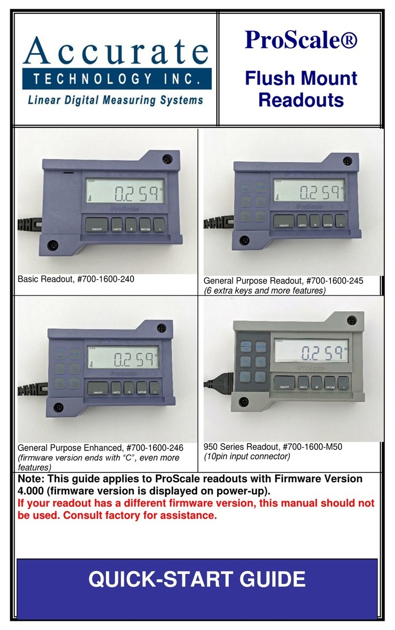
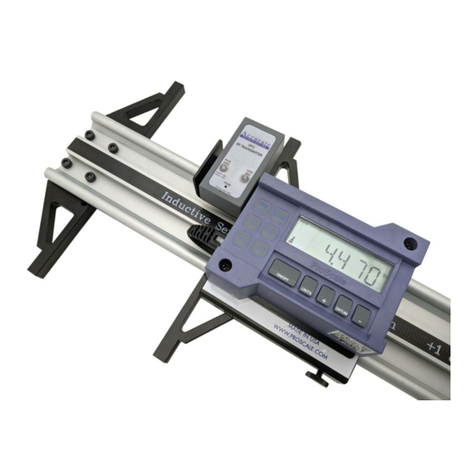
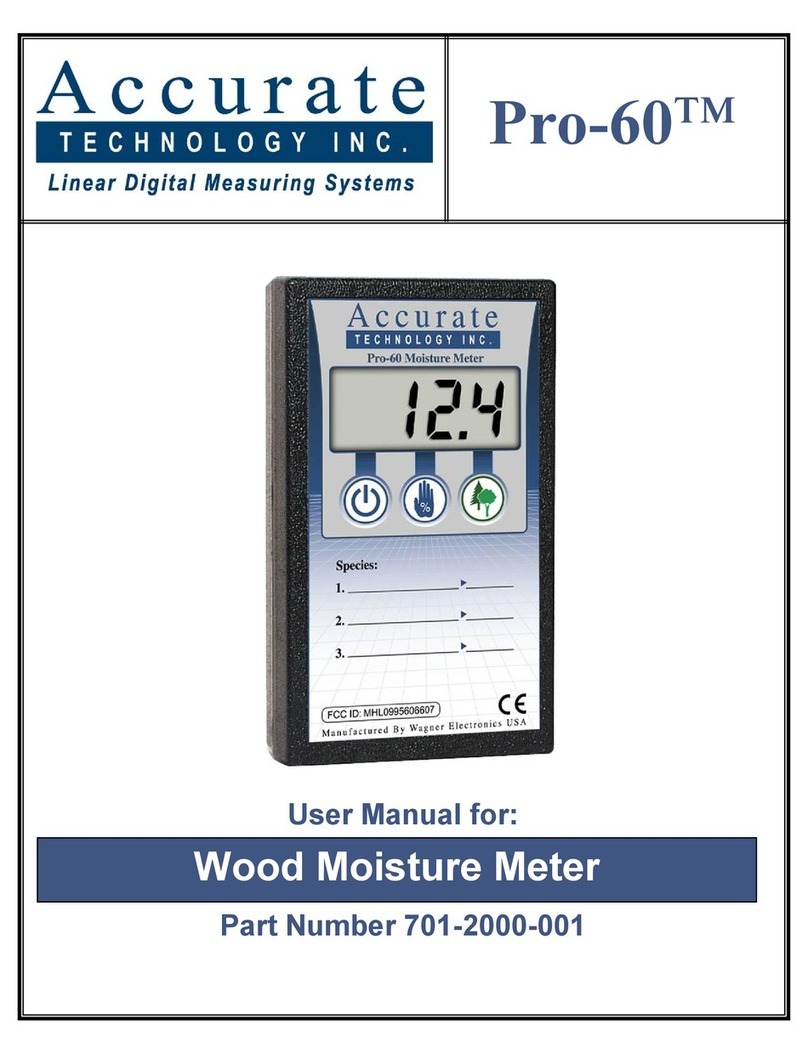
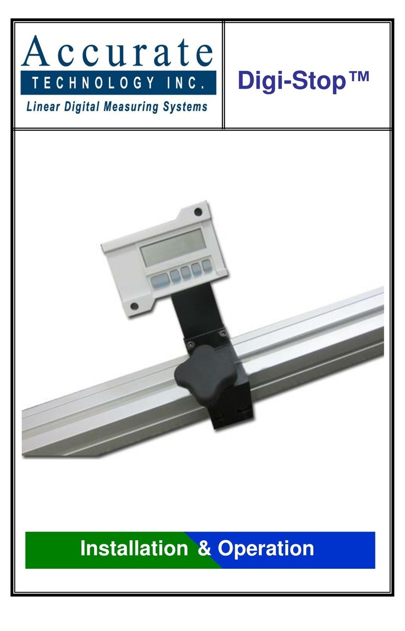
Other Accurate Technology Measuring Instrument manuals

Accurate Technology
Accurate Technology ProPanel-HD Instruction manual

Accurate Technology
Accurate Technology ProScale 19 Instruction Manual

Accurate Technology
Accurate Technology Pro-60 User manual

Accurate Technology
Accurate Technology ProScale 950 Series User manual

Accurate Technology
Accurate Technology Digi-Stop User manual

Accurate Technology
Accurate Technology Digi Scale Model 10 User manual

Accurate Technology
Accurate Technology DigiStop-4 Guide